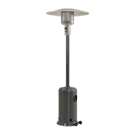
Cuisinart COH-400 User manual

INSPIRED OUTDOOR LIVING
PERFECT POSITION PROPANE
PATIO HEATER
MODEL NO: COH-400
INSPIRED OUTDOOR LIVING
CARBON MONOXIDE HAZARD
This appliance can produce
carbon monoxide which has no
odor.
Using it in an enclosed space can
kill you.
Never use this appliance in an
enclosed space such as a
camper, tent, car or home.
WARNING: For Outdoor Use Only.
Installation and service must be performed by a
qualified installer, service agency, or the gas supplier.
DANGER
If you smell gas:
• Shut off gas to the appliance.
• Extinguish any open flame.
• If odor continues, keep away from the
appliance and immediately call your gas
supplier or fire department.
Failure to follow these instructions could result in
fire or explosion, which could cause property
damage, personal injury, or death.
Improper installation, adjustment, alteration, service or
maintenance can cause property damage, injury or
death.
Read the installation, operating and maintenance
instructions thoroughly before installing or servicing
this equipment.
WARNING
DANGER
Do not store or use gasoline or other flammable vapors
and liquids in the vicinity of this or any other appliance.
A propane-cylinder not connected for use shall not be
stored in the vicinity of this or any other appliance.
DANGER
Customer Service Hotline
1-866-994-6390
DO NOT RETURN PRODUCT
TO THE STORE
Before visiting your local retailer, please email
or visit www.thefulhamgroup.com to online chat with a
representative. To best serve you, our Representatives
are available to answer your calls and live chats
Monday to Friday, 9 AM - 5 PM EST.
CALIFORNIA PROPOSITION 65 WARNING:
•WARNING: FUELS USED IN LIQUEFIED PROPANE
GAS APPLIANCES, AND THE PRODUCTS OF
COMBUSTION OF SUCH FUELS, CAN EXPOSE YOU
TO CHEMICALS INCLUDING BENZENE, WHICH IS
KNOWN TO THE STATE OF CALIFORNIA TO CAUSE
CANCER AND CAUSE BIRTH DEFECTS OR OTHER
REPRODUCTIVE HARM.
For more information go to:
www.P65Warnings.ca.gov.
INSTALLER: Leave this manual with the appliance.
CONSUMER: Retain this manual for future
reference.

IMPORTANT: ALL INSTRUCTIONS AND SAFEGUARDS ON THIS SECTION MUST BE FOLLOWED TO
PREVENT DAMAGE AND/OR INJURY.
USE CAUTION AND COMMON SENSE WHEN USING YOUR OUTDOOR PATIO HEATER. FAILURE
TO ADHERE TO THE SAFETY WARNING AND GUIDELINES IN THE MANUAL COULD RESULT IN
BODILY INJURY OR PROPERTY DAMAGE. SAVE THIS MANUAL FOR FUTURE REFERENCE.
•Do not allow children to climb the product.
•After a period of storage, inspect the patio heater for abrasion, wear or damage.
•Do not operate this patio heater while under the influence of drugs, alcohol, or while fatigued.
•Do not use this patio heater unless it is completely assembled, and all parts are securely fastened and tightened.
•Never use under low hanging tree branches, trellises or overhangs of any kind including covered porches.
•Always use patio heater in accordance with all applicable local, state, and national codes. Contact your local
fire department for details.
•DO NOT move this product when in use.
•Any modification of this appliance may be dangerous and will void the warranty.
•NEVER operate the heater with the top half covered (burner head, reflector, etc.).
•DO NOT leave this product unattended when in use.
•Always keep the cylinder level and vertical when positioning inside the base.
•ONLY use this appliance on a flat, LEVEL, nonflammable surface or ground.
•When positioning, ensure the unit is a minimum of 40 in. (1 m) from flammable items or structure from all sides
and above.
•Always leak test the unit before use, annually, or after storage, when parts are replaced/serviced or if the gas
cylinder is removed or replaced.
•When storing the appliance or gas cylinder, ensure they are away from flammable materials or liquids.
•Regularly check that the regulator seal and hose is fitted and that it is in good condition. Replace parts if
necessary.
•Always follow the care and maintenance instructions – regularly maintain your appliance.
•Always replace worn parts – do not use the appliance if a leak, wear, or damage is found.
•DO NOT store or cover the appliance until fully cooled.
•Always shut off the valve at the gas cylinder or the regulator before moving the appliance.
•In the event of high winds particular attention must be taken. Store the unit away or ensure it is at a safe distance
from other items in the event that the unit is blown over.
•Only use with gazebos specifically designed to be used with patio heaters.
•It is normal for the heater to smoke during the first few minutes of use.
•If you smell gas – turn off the appliance, disconnect from propane tank, and extinguish all flames. If the odor
continues, immediately contact your gas supplier.
•In the event of an uncontrollable fire, immediately disconnect and shut off the gas cylinder, move the gas
cylinder away from the fire, and contact the fire department. DO NOT PUT YOURSELF AT RISK!
SAFETYINFORMATION
2
WARNINGS AND USAGE
SAFETYINFORMATION

3
SAFETYINFORMATION
•Ensure aerosols are not used near this unit when in use.
•Ensure all packaging and plastic bags are disposed of safely.
•Ensure the heater is at a safe distance from glass and PVC doors and windows to stop damage from any heat.
•Read the warnings and use instructions before operation.
•Do not leave the lantern head in the upright position during rain or windy conditions or when the patio heater is
not in use or unattended. Always fold down the lantern head when not in use or during windy or rainy
conditions.
•This appliance features a flame failure and tilt device. In the event of a wind blowing the flame out or the unit
being tipped over, the gas supply will be cut off from the cylinder. In this event, the knobs should be set to off
and you should wait 5 minutes before re-lighting.
•This product will become hot when in use – take care when touching.
•Keep children and pets at a safe distance from the unit when in use.
•The outdoor patio heater is for adult use only.
•Keep the area around the patio heater clear and free of any combustible materials, gasoline, or any other
flammable liquids. Do not use patio heater in an explosive environment.
•Before each use make sure the patio heater is in good working condition. Inspect the hose and the unit itself.
•Never fold down the lantern head while the heater is operating.
•Warning: Upper Support Pole and top burner unit will get hot while in use. Use caution when handling.
•Do not store or use gasoline or any other flammable vapors or liquids in the vicinity of the patio heater.
•NEVER use indoors, in an enclosed area or below ground level.
•This appliance is intended for use with propane bottled gas only.
•Failure to read and follow these instructions could result in serious injury or damage to property.
•Wait until the unit has fully cooled before folding down the lantern head.
•Disconnect the gas cylinder and remove the gas cylinder from the heater before folding down the lantern head.
•Take care to support the lantern head while folding it down so that it does not drop suddenly.
•It is recommended that two people handle the heater when folding down the lantern head.
•Serious injury, death, and/or properly damage may occur if the above instructions are not followed exactly.
•NOTE: THESE INSTRUCTIONS ARE FOR YOUR SAFETY. PLEASE READ THEM THOROUGHLY BEFORE USE
AND RETAIN THEM FOR FUTURE REFERENCE.
•WARNING: Do not raise or lower the arm and burner head on an inclined surface. Dropping the burner head or
boom arm will change the center of gravity, the unit is meant to be used on a flat, hard, level surface only.
•WARNING: Tighten the swivel neck before raising or lowering arm. Do not raise the arm when the swivel neck is
loose.
•WARNING: Lowering the arm can create a pinch point, keep all body parts out of the path of travel.
•WARNING: When lowering the arm, do it slowly to allow the burner head to drop in a controlled manner.
Allowing the burner head to drop suddenly will result in damage and/or personal injury.
•WARNING: Do not light heater when burner is lowered as this could result in result in damage and/or personal
injury.
•WARNING: Do not pull out, pull on, fray, bend, twist or cut the regulator hose at the arm junction as this could
result in damage and/or personal injury.
•WARNING: Do not operate this heater without studying the entire contents of this document. Failure to do so
could lead to misuse resulting in damage and/or personal injury.
•CAUTION: Do not use heater if it shows any sign of damage.

4
•CAUTION: Do not touch the heating dome when burner is in operation, allow to cool down completely before
touching.
•CAUTION: Do not walk under burner head while it is in raised position.
•WARNING: Before allowing anyone to operate the heater, be certain that they have fully understood the manual.
•CAUTION: Keep people, children and pets clear while lifting or dropping the burner head.
•WARNING: Keep fingers and clothing clear of moving parts.
•WARNING: Loads, clothing and items shall not be placed, hung, or spread on burner head arm.
•WARNING: When in operation, lock swivel neck to limit movement.
•WARNING: When moving heater, lock swivel neck to limit movement.
•CAUTION: Do not stand on the table. It is only designed to hold food and drinks i.e. plates, cups, and bottles.
•CAUTION: Lock tank door when moving heater.
•CAUTION: Lock tank door when using heater.
•NOTE: Failure to heed any of the above can result in personal injury and/or damage.
•When an appliance is for connection to a gas cylinder, the installation shall conform with local codes or, in the
absence of local codes, with AMSI Z223.1/NFPA 54,CSA B149.1,or CAS B149.2.
SAFETYINFORMATION

Cover Page.…….............................…………......………………………….………...….………….………….….…………………..……..1
Safety Information……….….............……………………...………...….………….….………….……….............................……..……..2
Table of Contents……...........…….……………………..….………...….…………..............................………………..……….…….…..5
Exploded View…….................………….…………………….…………………….......................……….………................................6
What’s in the Box….………........................……..…..….……...…..............……………....……………….......................................7
Assembly Instructions…......................…………………...……………………….….…..............................…..................................9
Operation…..............................................................................….....……..……………………............................….................17
Care and Maintenance...............….........................……….………………......…………….……...….….…................................22
Warranty and Replacement Parts…..........……….....……….…………………….....…………..………..............................……...23
TABLE OF CONTENTS
5

EXPLODED VIEW
6
1
2
3
Carefully remove all pieces from the carton and make sure that you have all parts listed (refer to components list).
If you are missing parts, please contact 1-866-994-6390 for further assistance.
Use caution when removing the parts from packaging. It is recommended to wear gloves when assembling and
handling loose parts.
5
4
6
7
8
9
12
14
15
13
10
11

WHAT’S IN THE BOX
COMPONENTS
7
1Base (x1)
2Cylinder Chamber Supports (A, B, C) (x3)
3Lower Support Pole (x1)
4Cylinder Chamber Wall (x1)
5Cylinder Chamber Door (x1)
6Cylinder Chamber Top (x1)
7Swivel Head (x1)
PART DESCRIPTION QTY
8Upper Support Pole (x1)
9Main Burner and Hose (x1)
10 Burner Mesh (x1)
11 Parasol Supports (x3)
12 Handle (x1)
13 Regulator (x1)
14 Top Panel (x1)
15 Side Panels (x6)
PART DESCRIPTION QTY
HARDWARE INCLUDED
NOTE: Hardware not shown to actual size.
AA BB CC DD EE FF GG
HH
AA 1/4 in. dome head bolt (x24)
BB 1/4 in. nut (x33)
CC 1/4 in. allen bolt (x26)
DD 1/4 in. washer (x11)
EE 5/16 in. washer (x3)
FF 5/16 in. bolt (x3)
GG 1/4 in. spring washer (x11)
HH Allen Key (x1)
PART DESCRIPTION QTY

8
When you are ready to start, make sure that you have the right tools at hand, plenty of space and a clean dry
area for assembly.
WARNING: While every precaution has been made in the manufacture of this product, care must be taken during
assembly in case sharp edges are present.
NOTE: Please lay out all nuts and bolts and check lengths before assembly.
NOTE: It is recommended that the carton be cut open and spread out on the floor and used as a protective surface
during assembly.
NOTE: Refer to the assembly diagrams as necessary.
Assembly Time: 1 hour
TOOLS REQUIRED
Adjustable wrench x 2
1/4 in. Spanner
Phillips Head Screwdriver
PRE-ASSEMBLY
PLANNING ASSEMBLY
OVERALL HEIGHT 87 IN. APPROX.
OVERALL WEIGHT 110.25 LBS
OVERALL WIDTH 55 IN. APPROX.
HEATER HEAT INPUT ( QN) 38,200 BTU/H
HEATER GAS CONSUMPTION 1.77 LBS PER HOUR
HEATER INJECTOR SIZE 0.0744 IN.
SETTING PRESSURE 11.0 IN. PER W.C
REGULATOR OUTLET PRESSURE 11.0 IN. PER W.C
STANDARD CSA/ANSI Z83.26:2020, GASFIRED OUTDOOR INFRARED PATIO HEATERS
GAS SUPPLY PRESSURE MAX. 250 PSI, MIN.5 PSI
TECHNICAL DATA

ASSEMBLY INSTRUCTIONS
9
STEP 1 ASSEMBLING THE LEGS
•Attach the cylinder chamber supports (2) to the
corresponding section on the base (1) with six of the
bolts (CC).
•Finger tighten only at this stage.
1
2
CC
STEP 2 ATTACHING THE LOWER SUPPORT POLE
•Attach the lower support pole (3) to the cylinder
chamber supports (2) using six bolts (CC) and nuts
(BB).
•Finger tighten only at this stage.
3
2
CC
BB

ASSEMBLY INSTRUCTIONS
10
STEP 3 ATTACHING THE CYLINDER CHAMBER WALL
•Using six of the bolts (AA) and nuts (BB), attach the
cylinder chamber wall (4) to the cylinder chamber
supports (2).
•Finger tighten only at this stage.
STEP 4 ATTACHING THE CYLINDER CHAMBER DOOR
•Hang the cylinder chamber door (5) on the hinges.
•Ensure that the alignment is correct and tighten all
bolts securely.
2
4
5
AA
BB

ASSEMBLY INSTRUCTIONS
11
STEP 5 ATTACHING THE CYLINDER CHAMBER TOP
•Slide the cylinder chamber top (6) down over the
lower support pole (3) as shown and secure to the
cylinder chamber supports (2), using three bolts (CC)
and three nuts (BB).
3
6
CC 2
BB
STEP 6 ATTACHING THE PARASOL SUPPORTS
•Attach the three parasol supports (11) to the burner
mesh (10) using six of the pre-fitted bolts.
11
10

STEP 8 ATTACHING THE LANTERN
•Feed the hose down through the upper support pole
(8) and secure the assembled lantern to the upper
support pole (8) using four bolts (CC), washers (DD)
and spring washers (GG).
8
DD
GG
CC
ASSEMBLY INSTRUCTIONS
12
STEP 7 ASSEMBLING THE LANTERN
•Lower the burner mesh (10) onto the main burner
(9) and secure with three of the pre-fitted bolts.
10
9
NOTE: Make sure the rubber
siding is in place. If it is not,
please call Customer Service.

ASSEMBLY INSTRUCTIONS
13
STEP 9 ATTACHING THE HANDLE
•Attach the handle (12) to the upper support pole (8)
using three bolts (CC), washers (DD) and spring
washers (GG).
812
DD GG
CC
STEP 10 ATTACHING THE SWIVEL HEAD
•Attach the swivel head (7) to the upper arm
assembly using the pre-fitted bolt, as shown below.
7

ASSEMBLY INSTRUCTIONS
14
STEP 11 ASSEMBLING THE UPPER SECTION
•Feed the hose down through the lower support pole
(3) and lower the upper arm assembly, attaching the
swivel head (7) to the lower support pole (3) using
four bolts (CC), washers (DD) and spring washers
(GG). The arrow markings must be aligned for this
step. Keep the upper arm assembly folded down as
shown below.
STEP 12 ATTACHING THE REGULATOR AND
PROPANE BOTTLE
NOTE: THE CYLINDER MUST BE POSITIONED AS
SHOWN IN THE PATIO HEATER CYLINDER
CHAMBER TO PROVIDE VAPOR WITHDRAWAL.
•Connect the lantern and hose assembly to the
regulator (13) and secure tightly with the adjustable
wrenches.
•Screw the regulator (13) onto the gas cylinder (turn
clockwise to tighten it securely).
•Position the gas cylinder inside the cylinder chamber
as shown securing with the chain.
•Perform a Leak Test (see page 19).
13
The arrow markings must
be aligned for this step.
DD
GG
CC
3
7

ASSEMBLY INSTRUCTIONS
15
STEP 13 ASSEMBLING THE REFLECTOR
WARNING: While every precaution has been made in
the manufacture of this product, care must be taken
during assembly in case sharp edges are present.
•Loosely screw the side panels (15) together using
twelve bolts (AA) and nuts (BB), overlapping as
shown below.
•Attach the top panel (14) to the top of the assembled
side panels (15) using six bolts (AA) and nuts (BB),
and then fully tighten all bolts.
STEP 14 ATTACHING THE REFLECTOR TO THE
LANTERN
•Fit the reflector to the lantern using three bolts
(FF) and washers (EE).
BB
AA
AA
BB
15
14
15
EE
FF

ASSEMBLY INSTRUCTIONS
16
STEP 16 FITTING THE BATTERY
•Unscrew sparker button (A) and insert battery (B),
positive side facing outwards.
A B
STEP 15 SECURING THE UPPER SECTION
•Raise the upper arm upwards and secure using
the pre-fitted pin.

OPERATION
17
•Beware of the pinch point between the burner arm (horizontal rod) and the vertical pole,
when lowering and raising the head (Fig.1).
•Certain materials or items, when stored under the heater, will be subjected to radiant
heat and could be seriously damaged.
•Inspect the visible portion of the hose before each use of the appliance. The hose inside
cylinder pole housing should be checked annually and a leak test should be performed
when re-assembled.
•Children and adults should be alerted to the hazards of high surface temperatures and
should stay away to avoid burns or clothing ignition.
•Young children should be carefully supervised when they are in the area of the heater.
•Clothing or other flammable materials should not be hung from the heater, or placed on or near the heater.
•Any guard or other protective device removed for servicing the heater must be replaced prior to operating the heater.
•Installation and repair should be done by a qualified service person. The heater should be inspected before use
and at least annually by a qualified service person.
•More frequent cleaning may be required as necessary. It is imperative that the control compartment, burners
and circulating air passageways of the heater be kept clean.
•Keep the appliance area clear and free from combustible materials, gasoline and other flammable vapors and
liquids.
•Do not obstruct the flow of combustion and ventilation air.
•Keep the ventilation openings of the cylinder enclosure free and clear from debris.
•The propane-gas supply cylinder to be used must be: a. Constructed and marked in
accordance with the specifications for propane-gas cylinders of the U.S. Department
of Transportation (DOT); or the Standard for cylinders, Spheres and Tubes for
Transportation of Dangerous Goods and Commission, CAN/CSA-B339, as
applicable; b. Provided with a listed overfilling prevention device; and c. Provided
with a cylinder connection device compatible with the connection for the appliance. d. 20 lb (9 kg) cylinder.
LPG capacity 4.7 gallons (17.8 litres). Cylinder Dimensions: Height 17.75 in. (451 mm) and width 12.25 in.
(311 mm). The propane gas cylinder used must include a collar to protect the cylinder valve.
•A cylinder must be stored outdoors in a well-ventilated area out of reach of children. A disconnected cylinder
must have dust caps tightly installed and must not be stored in a building, garage or any enclosed area. The
pressure regulator and hose supplied must be used and any replacement pressure regulator or hose must be
those as specified by the manufacturer.
•Do not store spare propane-gas cylinder under or near this appliance.
•Never fill the cylinder beyond 80% full; and for appliances designed to use a CGA No. 791 connection, place
the dust cap on the cylinder valve outlet whenever the cylinder is not in use. Only install the type of dust cap on
the cylinder valve that is provided with the cylinder valve. Other types of caps or plugs may result in leakage of
propane.
POSITIONING INSTRUCTIONS
•This appliance is for OUTDOOR USE ONLY and should be placed in a well
ventilated area.
•A well ventilated area must have a minimum of 30% of its surface area open.
(Surface area is defined as the total surface of the walls.)
•The sides of the appliance should NEVER be closer than 40 in. (1 m) from any
combustible surface.
40 in. (1M) 40 in. (1M)
Fig. 1
12.2 in.
18 in.
8 in.
12.3 in.

OPERATION (CONTINUED)
18
•Keep this appliance away from any flammable materials!
•Important - Make sure the propane tank is placed level within the base.
•Should you need to change the gas bottle, confirm the gas supply is turned off at the regulator or bottle /
cylinder valve, and there are no sources of ignition (cigarettes, open flame, sparks, etc.) near before
proceeding.
•Inspect the gas hose to ensure it is free from any twisting or tension. The hose should hang freely with no bends,
folds, or kinks that could obstruct free flow of gas. Always inspect the hose for cuts, cracks, or excessive wear
before use. If the hose is damaged, it must be replaced with a hose suitable for use with propane gas.
CONNECTING TO THE CYLINDER
•Confirm all control knobs are in the off position.
•Connect the regulator to the gas bottle according to your regulator and bottle dealer instructions.
USE INSTRUCTIONS
•Before proceeding, make sure you understand the warnings section of this manual.
•This patio heater shall be used only in a well ventilated space and shall not be used in a building, garage or any
other enclosed area.
•This patio heater may be installed in shelter no more inclusive than; with walls on all sides but with no overhead
cover, within a partial enclosure that includes an overhead cover and no more than two side walls (these side
walls may be parallel, as in a breezeway or at right angles to each other), within a partial enclosure which
includes an overhead cover and three side walls, as long as 30% or more of the horizontal periphery of the
enclosure is permanently open.
ROTATING THE BURNER HEAD
Rotate the swivel lock in an
anti-clockwise direction to
release the rotation bracket.
Rotate the burner head to your
desired position.
Rotate the swivel lock in a
clockwise direction to tighten
the rotation bracket and lock
into position.

OPERATION (CONTINUED)
19
RAISING AND LOWERING THE BURNER HEAD
To fold the burner head down,
position the lantern opposite
the wheels as shown above.
Ensure that the swivel lock is in
the lock position.
Remove the lock pin and gently
lower down the burner head.
Put the lock pin back into
position.
Note: When storing the patio heater, ensure that it is in the folded down position.

20
X
XX
X
X
Fig. 3
BEFORE LIGHTING
1. Inspect the visible portion of the hose before each use of the appliance.
2. Inspect the entire hose assembly at least annually. If disassembly is required, perform a leak test to check the
connections upon re-assembly. Inspect the portion of the hose that is not visible. The hose assembly must be
replaced prior to the appliance being put into operation.
3. Replace the hose if there is evidence of excessive abrasion or wear, or if the hose is damaged. The replacement
hose assembly shall be that specified by the manufacturer.
LIGHTING INSTRUCTIONS
•Fit battery to sparker (see Fig. 2).
•Turn on the gas supply at the cylinder.
•Push the dial in and turn to position .
•While the dial is held pressed in at position , press the spark button to ignite the
heater.
•Hold the dial in for at least 10 seconds to ensure the heater stays lit.
•If the heater does not light after holding in the dial in for 20 seconds wait 5 minutes and try again. Do not
continuously hold the dial in as you may cause a build up of gas.
•In windy conditions, shield from wind to ensure easy lighting and hold the dial in for at least 20 seconds to
ensure the heater stays lit.
•Turn the control dial to high or low flame position as required. Correct operation of the heater is indicated by a
predominantly blue, quiet flame.
•If the sparker fails, you can light your patio heater using a match. To light your patio heater with a match:
1. Place the lit match through the gap below the burner mesh and wind guard. 2. Turn the control dial to the
position. After the burner ignites, keep the control dial held in for 10 seconds to ensure the burner stays lit and
then release. 3. If the burner does not light after holding the control dial in for 20 seconds with the lit match in
position, remove the match, turn the control dial to the off position, wait 5 minutes and then repeat.
TO TURN OFF
•Push the dial in and turn to position .
•Turn the gas off and disconnect at the cylinder when not in use.
•Remove battery from ignition unit during prolonged periods of non-use.
LEAK TESTING
Although all gas connections on the heater are leak tested prior to shipment, a complete gas tightness check must
be performed at the installation site due to possible shifts during shipment, installation or excessive pressure
unknowingly being applied to the unit. Periodically check the whole system for leaks and immediately check the
system if the smell of gas is detected. To check the connection at the gas hose/regulator/cylinder:
•Ensure you are in a well ventilated area.
•Confirm all control knobs are set to the "OFF" position.
•Turn ON LP gas tank at valve.
•Check for leaks by brushing a solution of 50% water and 50% dish soap at all "X"
locations (see Fig. 3).
•NEVER USE AN OPEN FLAME to test for leaks at any time.
•Check each place for growing bubbles. If "growing" bubbles appear, turn the Tank
Valve off and DO NOT use your heater until the leak is repaired.
OPERATION (CONTINUED)
Fig. 2
Table of contents
Other Cuisinart Patio Heater manuals