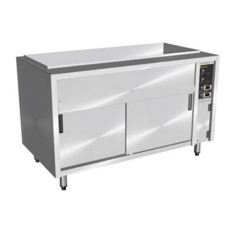
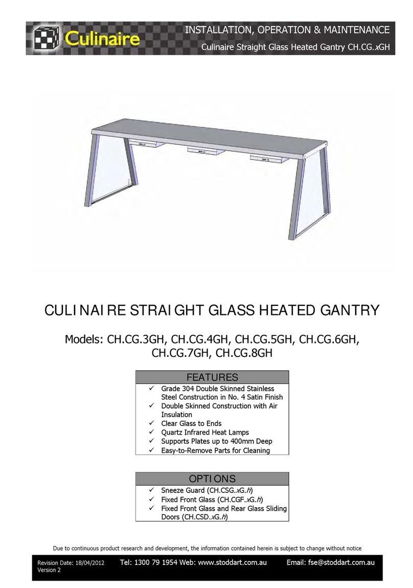
Culinaire Stoddart CR.BB.U.AG.RB User manual

A guide on the use, care and maintenance
of your quality Culinaire product
Models Horizontal:
CR.BB.U.AG.RB, CR.BB.U.AG.RB.PC, CR.BB.U.AG.RC, CR.BB.U.AG.RC.PC
CR.BB.U.FG.RB, CR.BB.U.FG.RB.PC, CR.BB.U.FG.RC, CR.BB.U.FG.RC.PC
CR.BB.U.SG.RB, CR.BB.U.SG.RB.PC, CR.BB.U.SG.RC, CR.BB.U.SG.RC.PC
CR.BB.U.SGR.RB, CR.BB.U.SGR.RB.PC, CR.BB.U.SGR.RC, CR.BB.U.SGR.RC.PC
Models Vertical:
CR.BB.V.AG.RB, CR.BB.V.AG.RB.PC, CR.BB.V.FG.RB, CR.BB.V.FG.RB.PC
CR.BB.V.SG.RB, CR.BB.V.SG.RB.PC, CR.BB.V.SGR.RB, CR.BB.V.SGR.RB.PC
BACK BAR REFRIGERATORS - REMOTE
HORIZONTAL / VERTICAL
SPECIFICATION, INSTALLATION
AND OPERATION MANUAL
READ ALL INSTRUCTIONS BEFORE USE
Revision: 02 - 8/03/2021 - A

Page Intentionally Left Blank
Page 1
Due to continuous product research and development,
the information contained herein is subject to change without notice.
www.stoddart.com.au
www.stoddart.co.nz

Page 2
Due to continuous product research and development,
the information contained herein is subject to change without notice.
www.stoddart.com.au
www.stoddart.co.nz
Introduction
Your New Culinaire Product� � � � � � � � � � � � � � � � � � � 3
Australia and New Zealand Warranty � � � � � � � � � � � � � � 4
Warranty Period
Warranty Registration
General Precautions � � � � � � � � � � � � � � � � � � � � � � 4
Installation
Product Overview� � � � � � � � � � � � � � � � � � � � � � � � 5
Setting Up � � � � � � � � � � � � � � � � � � � � � � � � � � � 6
Handling
Unpacking
Positioning
Refrigeration Connections � � � � � � � � � � � � � � � � � � � 7
Pre-Installation Pressure Test
TX Valves
Refrigerant
Solenoid Valve - Liquid Line
Isolation Valves
Refrigeration Lines
Condenser Unit
Remote Unit Leak Testing Diagram
Climate Classes
Electrical Connection � � � � � � � � � � � � � � � � � � � � � 10
Plumbing Connections � � � � � � � � � � � � � � � � � � � � 10
Shelves� � � � � � � � � � � � � � � � � � � � � � � � � � � � 10
Specification
Technical Specifications � � � � � � � � � � � � � � � � � � � 11
CR.BB.U.xx.RB.x
CR.BB.U.xx.RC.x
CR.BB.V.xx.RC.x
Operation
Control Panel � � � � � � � � � � � � � � � � � � � � � � � � � 17
Initial Start-up & Operation � � � � � � � � � � � � � � � � � � 17
Initial Start Up
Operation
Loading Restrictions
Defrost Cycle
After Service - Information
After Service - Storage
Temperature Adjustment � � � � � � � � � � � � � � � � � � � 19
Cleaning and Maintenance
Cleaning � � � � � � � � � � � � � � � � � � � � � � � � � � � 20
Cleaning and Maintenance Schedule
Materials Required
General Information
Corrosion Protection
Surface Finish
Refrigerator
Doors
External Surfaces
Ventilation Panels
Troubleshooting � � � � � � � � � � � � � � � � � � � � � � � 22
Disposal � � � � � � � � � � � � � � � � � � � � � � � � � � � 23

Page 3
Due to continuous product research and development,
the information contained herein is subject to change without notice.
www.stoddart.com.au
www.stoddart.co.nz
Thank you for choosing this quality Culinaire product�
All Culinaire products are designed and manufactured to meet the needs of food service professionals� By caring for and maintaining your
new Culinaire product in accordance with these instructions, will provide many years of reliable service�
Stoddart is a wholly Australian owned company, which manufactures and/or distributes a comprehensive range of food service equipment for
kitchens, food preparation and presentation� Stoddart products are manufactured and/or engineered in Australia to provide excellent results
whilst offering value-for-money, ease-of-use and reliability�
Carefully read this instruction booklet, as it contains important advice for safe installation, operation and maintenance�
Keep this booklet on hand in a safe place for future reference by other operators or users�
Stoddart design, manufacture & distribute Food Service Equipment (appliances) exclusively for the commercial market.
This appliance is not designed nor intended for household or domestic use and must not be used for this purpose.
This product is intended for commercial use, and in line with Australian electrical safety standards the following warnings are provided:
• This product is not intended for use by persons (including children) with reduced physical, sensory or mental capabilities, or lack of
experience and knowledge, unless they have been given supervision or instruction concerning the use of the product by a person
responsible for their safety� Children should be supervised to ensure that they do not play with the product
• If the supply cord is damaged, it must be replaced by the manufacturer, its service agent or similarly qualified persons in order to avoid
a hazard
The manufacturer and distributor cannot be held responsible or liable for any injuries or damages of any kind that occur
to persons, units or others, due to abuse and misuse of this unit in regards to installation, removal, operation, servicing or
maintenance, or lack of conformity with the instructions indicated in this documentation�
Disclaimer
All units made by the manufacturer are delivered assembled, where possible, and ready to install� Any installation, removal,
servicing, maintenance and access or removal of any parts, panels or safety barriers that is not permitted, does not comply
in accordance to this documentation, or not performed by a TRAINED AND AUTHORISED SPECIALIST will result in the
IMMEDIATE LOSS OF THE WARRANTY.
The manufacturer cannot be held responsible or liable for any unauthorised modifications or repairs� All modifications or
repairs must be approved by the manufacturer in writing before initiating� All modifications or repairs performed to this unit
must be performed at all times by a TRAINED AND AUTHORISED SPECIALIST.
Your New Culinaire Product
To register your new product, Follow the below Link/QR code�
www�stoddart�com�au/warranty-information
All Stoddart manufactured and distributed products are covered by Stoddart’s standard Australia and New Zealand Product Warranty (minimum
12 month on-site parts and labour, terms and conditions apply)� Further to this standard warranty, certain products have access to an extended
warranty� Full terms, conditions and exclusions can be found using the below Link/QR code�
Warranty & Registration
Introduction

Page 4
Due to continuous product research and development,
the information contained herein is subject to change without notice.
www.stoddart.com.au
www.stoddart.co.nz
Thank you for choosing this quality Culinaire product�
All Culinaire products are designed and manufactured to meet the needs of food service professionals� By caring for and maintaining your
new Culinaire product in accordance with these instructions, will provide many years of reliable service�
Stoddart is a wholly Australian owned company, which manufactures and/or distributes a comprehensive range of food service equipment for
kitchens, food preparation and presentation� Stoddart products are manufactured and/or engineered in Australia to provide excellent results
whilst offering value-for-money, ease-of-use and reliability�
Carefully read this instruction booklet, as it contains important advice for safe installation, operation and maintenance�
Keep this booklet on hand in a safe place for future reference by other operators or users�
Stoddart design, manufacture & distribute Food Service Equipment (appliances) exclusively for the commercial market.
This appliance is not designed nor intended for household or domestic use and must not be used for this purpose.
This product is intended for commercial use, and in line with Australian electrical safety standards the following warnings are provided:
• This product is not intended for use by persons (including children) with reduced physical, sensory or mental capabilities, or lack of
experience and knowledge, unless they have been given supervision or instruction concerning the use of the product by a person
responsible for their safety� Children should be supervised to ensure that they do not play with the product
• If the supply cord is damaged, it must be replaced by the manufacturer, its service agent or similarly qualified persons in order to avoid
a hazard
The manufacturer and distributor cannot be held responsible or liable for any injuries or damages of any kind that occur
to persons, units or others, due to abuse and misuse of this unit in regards to installation, removal, operation, servicing or
maintenance, or lack of conformity with the instructions indicated in this documentation�
Disclaimer
All units made by the manufacturer are delivered assembled, where possible, and ready to install� Any installation, removal,
servicing, maintenance and access or removal of any parts, panels or safety barriers that is not permitted, does not comply
in accordance to this documentation, or not performed by a TRAINED AND AUTHORISED SPECIALIST will result in the
IMMEDIATE LOSS OF THE WARRANTY.
The manufacturer cannot be held responsible or liable for any unauthorised modifications or repairs� All modifications or
repairs must be approved by the manufacturer in writing before initiating� All modifications or repairs performed to this unit
must be performed at all times by a TRAINED AND AUTHORISED SPECIALIST.
• All units MUST be installed according to the procedures stated in the installation section of this manual
• In the case of new personnel, training is to be provided before operating the equipment
• DO NOT use this unit for any other purpose than its intended use
• DO NOT store explosive substances such as aerosol cans with a flammable propellant in or near this unit
• Keep fingers out of “pinch point” areas
• Unit is not waterproof DO NOT use jet sprays, hoses or pour water over/on the exterior of the unit
• Only use this unit with voltage specified on the rating label
• DO NOT remove any cover panels that may be on the unit
• DO NOT use sharp objects to activate controls
• DO NOT use sharp objects to remove ice from the unit
• If any fault is detected, refer to troubleshooting
• The manufacturer declines any liability for damages to persons and/or things due to an improper/wrong and/or unreasonable use of the
machine
• Only specifically trained/qualified Technicians (Stoddart, one of our service agents, or a similarly qualified persons) should carry out any
and all repairs, maintenance and services
When using any electrical unit, safety precautions must always be observed�
Our units have been designed for high performance� Therefore, the unit must be used exclusively for the purpose for which it has been designed�
General Precautions
To register your new product, Follow the below Link/QR code�
www�stoddart�com�au/warranty-information
All Stoddart manufactured and distributed products are covered by Stoddart’s standard Australia and New Zealand Product Warranty (minimum
12 month on-site parts and labour, terms and conditions apply)� Further to this standard warranty, certain products have access to an extended
warranty� Full terms, conditions and exclusions can be found using the below Link/QR code�
Warranty & Registration
Warranty Registration
Warranty Period
Australia and New Zealand Warranty
Introduction

Page 5
Due to continuous product research and development,
the information contained herein is subject to change without notice.
www.stoddart.com.au
www.stoddart.co.nz
Control Panel
Doors
Code Explanation
CR = Culinaire Refrigerated
BB = Back Bar
U= Under Counter
AG = Aluminium Framed Glass Door
FG = Frameless Glass Door
SG = Stainless Steel Framed Glass Door
SGR = Stainless Steel Framed Glass Door Recessed Handle
RB = Remote Control Box
RC = Remote Service Compartment
PC = Powder Coated
L= Left Hand Services (Add L to product code eg. CR.BB.U.AG.RBL.5)
2-7 = Number of Doors
Installation
Product Overview
CAUTION
This unit includes refrigeration components.
Cold surfaces can burn DO NOT touch these surfaces
IMPORTANT
This unit is not designed to cool down hot/warm
product. It only maintains the product at the
controlled 2°C - 4°C

Page 6
Due to continuous product research and development,
the information contained herein is subject to change without notice.
www.stoddart.com.au
www.stoddart.co.nz
Installation
Setting Up
Handling
Unpacking
Positioning
• Use suitable means to move the unit;
- For smaller items use two people
- For large items a fork lift, pallet trolley or similar (the forks should reach completely beneath the pallet)
• Check the unit for damage before and after unpacking� If unit is damaged, contact the distributor and manufacturer
• Should any item have physical damage, report the details to the freight company and to the agent responsible for the dispatch within
seven (7) days of receipt� No claims will be accepted or processed after this period
• The unit is supplied fully assembled
• Remove all protective plastic film, tapes, ties and packers before installing and operating
• Clean off any remaining residue from the interior/exterior of the unit using a clean cloth dampened with warm soapy water
• When moving the unit, ensure the cabinet is upright at all times
• When positioning the unit, avoid direct sunlight, warm drafts and heated areas for the unit to maintain the normal operating
temperature
• Do not position the unit in:
- Wet areas
- Near heat and/or steam sources
- Near flammable substances
• Ensure the unit is positioned on a level surface to allow all the condensation to properly burn off and prevent the burn off tray
overflowing
• Allow an air gap between the unit and other objects or surfaces� A minimum gap of 100mm from all sides is recommend for normal
operational use (if the unit is near any heat sensitive material we suggest you allow additional space), example below
• After positioning the unit, allow the refrigeration gas to settle for at least 2 hours before switching ON
• Please consult national and local standards to ensure that your unit is positioned in accordance with any existing requirement
WARNING
Improper installation, adjustments, alterations, service or
maintenance can cause property damage, injury or death.
100mm
APPLIANCE
100mm
100mm
Front

Page 7
Due to continuous product research and development,
the information contained herein is subject to change without notice.
www.stoddart.com.au
www.stoddart.co.nz
Installation
Refrigeration Connections
• All refrigeration lines are pressurised with nitrogen before leaving the factory� Exported units are de-pressurised before shipping to a
country other than Australia
• Refrigeration lines are tested at 1725kPa (250psi) for 24 hours in the factory� For safety, the pressure is reduced before leaving the factory
• Before use, the system MUST be checked for leaks� Check the pressure tag attached to the refrigeration lines� If the pressure tag is lost,
the preset pressure of the lines when leaving the factory should be 1380kPa (200psi)� Contact the manufacturer to confirm
• Any pressure loss MUST be reported to the distributor or manufacturer and fixed before the unit is used
• If exported, the system MUST be tested again for 24 hours before attaching the external refrigeration lines
• The solenoid is not sold or supplied with this product or by Stoddart� For purchasing and installation of the solenoid contact a local
refrigeration company
• A 3 core flex is supplied for fitting the solenoid and is connected into the switching output 5 of the electronic controller� The switching
output for the solenoid is marked on the 3 core flex
• Ensure the refrigeration lines are thoroughly pressure tested and vacuumed after fitting the solenoid valve�
• Isolation valves (suction line and liquid line) are not sold or supplied with this product or by Stoddart� For purchasing and installation of
the solenoid contact a local refrigeration company
• Ensure the refrigeration lines are thoroughly pressure tested and vacuumed after fitting the ball valve
• All external refrigeration lines are not sold or supplied with this product or by Stoddart� For purchasing and installation of refrigeration
lines contact a local refrigeration company
• The connecting refrigeration lines are on the side of the unit or inside the service compartment
• A 3/8” liquid line, and 1/2” suction line are provided to attach the external refrigeration lines
• The suction lines must be insulated
• All refrigeration lines MUST be vacuumed and pressure tested before using
• Condenser units are not sold or supplied with this product or by Stoddart� For purchasing and installation of a condensate unit contact a
local refrigeration company
• Ensure the condenser unit has right capabilities for this unit and other units that will be attached
• Refrigeration capacity is on the rating label on the service compartment or in the specification manual
• Do NOT overload the condenser unit
• The TUA or TUAE TX valve is supplied with the unit� Check the specification manual for more information
• Ensure the TX valve is working properly before use
• This unit designed for R404A refrigerant�
Pre-Installation Pressure Test
TX Valves
Refrigerant
Solenoid Valve - Liquid Line
Isolation Valves
Refrigeration Lines
Condenser Unit
IMPORTANT
This refrigeration system must be installed in accordance with
local refrigeration standards

Page 8
Due to continuous product research and development,
the information contained herein is subject to change without notice.
www.stoddart.com.au
www.stoddart.co.nz
Installation
Remote Unit Leak Testing Diagram
Check all
pipes are
fully welded.
Connect the
pressure gauge to
the pipe work and
fill with dry
nitrogen to
1725kPa (250psi).
Close the
pressure gauge
and note the
pressure
reading.
Using a
soapy
solution
check all the
joints for
leaks.
If leaks exist
START
If leaks exist
If NO leaks exist
If NO leaks exist
Connect the vacuum pump
to the system and pull a
deep vacuum to a pressure
of less than 41Pa absolute
(310 microns of mercury).
Leave the system for
45 minutes. Check the
gauge reading.
Leave the
system for 24
hours. Check
the gauge
reading.
Fill the system
with refrigerant.

Page 9
Due to continuous product research and development,
the information contained herein is subject to change without notice.
www.stoddart.com.au
www.stoddart.co.nz
Installation
Test room Climatic classes & classifications indicated on rating labels are specified in ISO-23953-2 (& AS-1731) e�g� Climatic Class:
• 3=25°C @ 60% humidity,
• 4=30°C @ 55% humidity &
• 5=40 °C @ 40% humidity�
The cabinet classification shall be given by the combination of climate class and M-package temperature class� Under AS & EU energy
regulations (MEPS) some display &/or storage cabinets are required to be labelled� E�g� a cabinet tested in a test room climate Class 3 with an
M1 class package would be designated as 3M1� Refrigerated Units in Commercial Kitchens would normally be climate class 4
CLIMATE CLASSES
Test Room Climate Class Dry bulb temperature °C Relative humidity % Dew point °C Water weightin dry air g/kg
0 20 50 9.3 7.3
1 16 80 12.6 9.1
2 22 65 15.2 10.8
3 25 60 16.7 12
4 30 55 20 14.8
5 40 40 23.9 18.8
6 27 70 21 15.8
7 35 75 30 27.3
M-PACKAGE TEMPERATURE CLASSES
Class
The highest temperature
0ah of the warmest
M-package equal to
or lower than °C
The lowest temperature 0b
of the coldest
M-package equal to
or higher than °C
The lowest temperature
0al of the warmest
M-package equal to
or lower than °C
L1 20 N/A -18
L2 16 N/A -18
L3 22 N/A -15
M1 25 -1 N/A
M2
H1 30 -1
+1
N/A
N/A
H2 40 -1 N/A
SSpecial Classification
Note these ‘Classifications” should not be confused with Cabinet “Types” used for MEPS registration e.g.
HC1-6, VC1-4, YC1-4 or HF1-6, VF1-4 or YF1-4
Climate Classes

Page 10
Due to continuous product research and development,
the information contained herein is subject to change without notice.
www.stoddart.com.au
www.stoddart.co.nz
Installation
Shelves
1� The shelf support pin needs to be facing up
2� Squeeze the pin to fit the bottom of the clip in
3� The shelf clips clip into the rail
4� All four pins for the shelf need to be at the same height for a level shelf
5� The outer frame of the shelf fits over the shelf
Note: Do not use pliers when installing shelf clips
Single Phase Units:
• Supplied and fitted with an appropriately rated plug and lead, indicated as:
- 10A plug & lead fitted
This unit must be installed in accordance with AS/NZS 60335.1
Some procedures in this manual require the power to the equipment to be turned off and
isolated. Turn the power OFF at the power point and unplug the power supply lead by the plug
body. If the power point is not readily accessible turn the equipment off at the isolation switch
or the circuit breaker in the switchboard. Attach a yellow “CAUTION-DO NOT OPERATE” tag.
This must be performed where relevant unless the procedures specify otherwise.
FAILURE TO DO SO MAY RESULT IN ELECTRIC SHOCK.
WARNING
Notes:
• If the supply cord is damaged, it must be replaced by the manufacturer, its service agent or similarly qualified persons in order to avoid a
hazard� Please contact Stoddart for parts and we will advise how to do this in order to avoid any electrical hazard
• The power cable should be dry and/or isolated from moisture or water
Electrical Connection
Plumbing Connections
• The drainage must be drained to a tundish
• The unit MUST be on a level surface for the water to drain properly
IMPORTANT
This unit must be installed in accordance with AS/NZ 3500.1

Page 11
Due to continuous product research and development,
the information contained herein is subject to change without notice.
www.stoddart.com.au
www.stoddart.co.nz
Technical Specifications
SPECIFICATIONS
Model CR.BB.U.AG.RB.2 / CR.BB.U.AG.RB.PC.2
CR.BB.U.FG.RB.2 / CR.BB.U.FG.RB.PC.2
CR.BB.U.SG.RB.2 / CR.BB.U.SG.RB.PC.2
CR.BB.U.SGR.RB.2 / CR.BB.U.SGR.RB.PC.2
CR.BB.U.AG.RB.3 / CR.BB.U.AG.RB.PC.3
CR.BB.U.FG.RB.3 / CR.BB.U.FG.RB.PC.3
CR.BB.U.SG.RB.3 / CR.BB.U.SG.RB.PC.3
CR.BB.U.SGR.RB.3 / CR.BB.U.SGR.RB.PC.3
CR.BB.U.AG.RB.4 / CR.BB.U.AG.RB.PC.4
CR.BB.U.FG.RB.4 / CR.BB.U.FG.RB.PC.4
CR.BB.U.SG.RB.4 / CR.BB.U.SG.RB.PC.4
CR.BB.U.SGR.RB.4 / CR.BB.U.SGR.RB.PC.4
Width 1150mm 1670mm 2190mm
Depth 700mm 700mm 700mm
Height 960mm 960mm 960mm
Voltage / Frequency 240V / 50Hz 240V / 50Hz 240V / 50Hz
Power (kW) 0.4kW 0.6kW 0.9kW
Connection 1Ø + N + E 1Ø + N + E 1Ø + N + E
Gas Type R404A R404A R404A
Refrigeration Systems Remote 800W -10°C SST Remote 1250W -10°C SST Remote 1650W -10°C SST
Temperature Range 2-4°C 2-4°C 2-4°C
SPECIFICATIONS
Model CR.BB.U.AG.RB.5 / CR.BB.U.AG.RB.PC.5
CR.BB.U.FG.RB.5 / CR.BB.U.FG.RB.PC.5
CR.BB.U.SG.RB.5 / CR.BB.U.SG.RB.PC.5
CR.BB.U.SGR.RB.5 / CR.BB.U.SGR.RB.PC.5
CR.BB.U.AG.RB.6 / CR.BB.U.AG.RB.PC.6
CR.BB.U.FG.RB.6 / CR.BB.U.FG.RB.PC.6
CR.BB.U.SG.RB.6 / CR.BB.U.SG.RB.PC.6
CR.BB.U.SGR.RB.6 / CR.BB.U.SGR.RB.PC.6
CR.BB.U.AG.RB.7 / CR.BB.U.AG.RB.PC.7
CR.BB.U.FG.RB.7 / CR.BB.U.FG.RB.PC.7
CR.BB.U.SG.RB.7 / CR.BB.U.SG.RB.PC.7
CR.BB.U.SGR.RB.7 / CR.BB.U.SGR.RB.PC.7
Width 2710mm 3230mm 3750mm
Depth 700mm 700mm 700mm
Height 960mm 960mm 960mm
Voltage / Frequency 240V / 50Hz 240V / 50Hz 240V / 50Hz
Power (kW) 1.2kW 1.5kW 1.8kW
Connection 1Ø + N + E 1Ø + N + E 1Ø + N + E
Gas Type R404A R404A R404A
Refrigeration Systems Remote 2050W -10°C SST Remote 2500W -10°C SST Remote 3050W -10°C SST
Temperature Range 2-4°C 2-4°C 2-4°C
CR.BB.U.xx.RB.x
Specification
Code Explanation
CR = Culinaire Refrigerated
BB = Back Bar
U= Under Counter
AG = Aluminium Framed Glass Door
FG = Frameless Glass Door
SG = Stainless Steel Framed Glass Door
SGR = Stainless Steel Framed Glass Door Recessed Handle
RB = Remote Control Box
RC = Remote Service Compartment
PC = Powder Coated
L= Left Hand Services (Add L to product code eg. CR.BB.U.AG.RBL.5)
2-7 = Number of Doors

Page 12
Due to continuous product research and development,
the information contained herein is subject to change without notice.
www.stoddart.com.au
www.stoddart.co.nz
700mm 960mm
2190mm
2710mm
3230mm
3750mm
1670mm
1150mm
180mm
FRONT VIEW
TOP VIEW
Specification

Page 13
Due to continuous product research and development,
the information contained herein is subject to change without notice.
www.stoddart.com.au
www.stoddart.co.nz
SPECIFICATIONS
Model CR.BB.U.AG.RC.2 / CR.BB.U.AG.RC.PC.2
CR.BB.U.FG.RC.2 / CR.BB.U.FG.RC.PC.2
CR.BB.U.SG.RC.2 / CR.BB.U.SG.RC.PC.2
CR.BB.U.SGR.RC.2 / CR.BB.U.SGR.RC.PC.2
CR.BB.U.AG.RC.3 / CR.BB.U.AG.RC.PC.3
CR.BB.U.FG.RC.3 / CR.BB.U.FG.RC.PC.3
CR.BB.U.SG.RC.3 / CR.BB.U.SG.RC.PC.3
CR.BB.U.SGR.RC.3 / CR.BB.U.SGR.RC.PC.3
CR.BB.U.AG.RC.4 / CR.BB.U.AG.RC.PC.4
CR.BB.U.FG.RC.4 / CR.BB.U.FG.RC.PC.4
CR.BB.U.SG.RC.4 / CR.BB.U.SG.RC.PC.4
CR.BB.U.SGR.RC.4 / CR.BB.U.SGR.RC.PC.4
Width 1450mm 1970mm 2490mm
Depth 700mm 700mm 700mm
Height 960mm 960mm 960mm
Voltage / Frequency 240V / 50Hz 240V / 50Hz 240V / 50Hz
Power (kW) 0.4kW 0.6kW 0.9kW
Connection 1Ø + N + E 1Ø + N + E 1Ø + N + E
Gas Type R404A R404A R404A
Refrigeration Systems Remote 800W -10°C SST Remote 1250W -10°C SST Remote 1650W -10°C SST
Temperature Range 2-4°C 2-4°C 2-4°C
SPECIFICATIONS
Model CR.BB.U.AG.RC.5 / CR.BB.U.AG.RC.PC.5
CR.BB.U.FG.RC.5 / CR.BB.U.FG.RC.PC.5
CR.BB.U.SG.RC.5 / CR.BB.U.SG.RC.PC.5
CR.BB.U.SGR.RC.5 / CR.BB.U.SGR.RC.PC.5
CR.BB.U.AG.RC.6 / CR.BB.U.AG.RC.PC.6
CR.BB.U.FG.RC.6 / CR.BB.U.FG.RC.PC.6
CR.BB.U.SG.RC.6 / CR.BB.U.SG.RC.PC.6
CR.BB.U.SGR.RC.6 / CR.BB.U.SGR.RC.PC.6
CR.BB.U.AG.RC.7 / CR.BB.U.AG.RC.PC.7
CR.BB.U.FG.RC.7 / CR.BB.U.FG.RC.PC.7
CR.BB.U.SG.RC.7 / CR.BB.U.SG.RC.PC.7
CR.BB.U.SGR.RC.7 / CR.BB.U.SGR.RC.PC.7
Width 3010mm 3530mm 4050mm
Depth 700mm 700mm 700mm
Height 960mm 960mm 960mm
Voltage / Frequency 240V / 50Hz 240V / 50Hz 240V / 50Hz
Power (kW) 1.2kW 1.5kW 1.8kW
Connection 1Ø + N + E 1Ø + N + E 1Ø + N + E
Gas Type R404A R404A R404A
Refrigeration Systems Remote 2050W -10°C SST Remote 2500W -10°C SST Remote 3050W -10°C SST
Temperature Range 2-4°C 2-4°C 2-4°C
CR.BB.U.xx.RC.x
Specification

Page 14
Due to continuous product research and development,
the information contained herein is subject to change without notice.
www.stoddart.com.au
www.stoddart.co.nz
700mm 960mm
2490mm
3010mm
3530mm
4050mm
1970mm
1450mm
FRONT VIEW
TOP VIEW
Specification

Page 15
Due to continuous product research and development,
the information contained herein is subject to change without notice.
www.stoddart.com.au
www.stoddart.co.nz
SPECIFICATIONS
Model CR.BB.V.AG.RB.2 / CR.BB.V.AG.RB.PC.2
CR.BB.V.FG.RB.2 / CR.BB.V.FG.RB.PC.2
CR.BB.V.SG.RB.2 / CR.BB.V.SG.RB.PC.2
CR.BB.V.SGR.RB.2 / CR.BB.V.SGR.RB.PC.2
CR.BB.V.AG.RB.3 / CR.BB.V.AG.RB.PC.3
CR.BB.V.FG.RB.3 / CR.BB.V.FG.RB.PC.3
CR.BB.V.SG.RB.3 / CR.BB.V.SG.RB.PC.3
CR.BB.V.SGR.RB.3 / CR.BB.V.SGR.RB.PC.3
CR.BB.V.AG.RB.4 / CR.BB.V.AG.RB.PC.4
CR.BB.V.FG.RB.4 / CR.BB.V.FG.RB.PC.4
CR.BB.V.SG.RB.4 / CR.BB.V.SG.RB.PC.4
CR.BB.V.SGR.RB.4 / CR.BB.V.SGR.RB.PC.4
Width 1450mm 1970mm 2490mm
Depth 700mm 700mm 700mm
Height 1900mm 1900mm 1900mm
Voltage / Frequency 240V / 50Hz 240V / 50Hz 240V / 50Hz
Power (kW) 0.4kW 0.6kW 0.9kW
Connection 1Ø + N + E 1Ø + N + E 1Ø + N + E
Gas Type R404A R404A R404A
Refrigeration Systems Remote 1400W -10°C SST Remote 2200W -10°C SST Remote 2950W -10°C SST
Temperature Range 2-4°C 2-4°C 2-4°C
SPECIFICATIONS
Model CR.BB.V.AG.RB.5 / CR.BB.V.AG.RB.PC.5
CR.BB.V.FG.RB.5 / CR.BB.V.FG.RB.PC.5
CR.BB.V.SG.RB.5 / CR.BB.V.SG.RB.PC.5
CR.BB.V.SGR.RB.5 / CR.BB.V.SGR.RB.PC.5
CR.BB.V.AG.RB.6 / CR.BB.V.AG.RB.PC.6
CR.BB.V.FG.RB.6 / CR.BB.V.FG.RB.PC.6
CR.BB.V.SG.RB.6 / CR.BB.V.SG.RB.PC.6
CR.BB.V.SGR.RB.6 / CR.BB.V.SGR.RB.PC.6
Width 3010mm 3530mm
Depth 700mm 700mm
Height 1900mm 1900mm
Voltage / Frequency 240V / 50Hz 240V / 50Hz
Power (kW) 1.2kW 1.5kW
Connection 1Ø + N + E 1Ø + N + E
Gas Type R404A R404A
Refrigeration Systems Remote 3300W -10°C SST Remote 3950W -10°C SST
Temperature Range 2-4°C 2-4°C
CR.BB.V.xx.RC.x
Specification

Page 16
Due to continuous product research and development,
the information contained herein is subject to change without notice.
www.stoddart.com.au
www.stoddart.co.nz
Specification
700mm 1900mm
2190mm
2710mm
3230mm
1670mm
1150mm
180mm
FRONT VIEW
TOP VIEW

Page 17
Due to continuous product research and development,
the information contained herein is subject to change without notice.
www.stoddart.com.au
www.stoddart.co.nz
Operation
Control Panel
Glass Heater
Lights ON/OFF
Light Dimmer
Power ON/OFF
Initial Start Up
• Before switching ON the unit, ensure the unit is installed correctly
• Once switched ON, check that the air is flowing within the unit� Check the lights and the door surround heaters are working
• After 45 minutes check the cabinet temperature has reached 2°C - 4°C
• Leave the unit to operate for 1-2 hours to remove any fumes or odours
• Let the unit cool then clean the whole unit, including the shelves, before placing in product
Operation
• All food MUST be pre-chilled to before loading into the unit
• Ensure the unit is maintaining temperature is between 2°C - 4°C
• Unit is loaded via the glass doors� Ensure the doors are CLOSED when not loading to maintain the temperature
• All products MUST be displayed on the shelves� The top, centre and bottom shelves are for display� The base shelf is for quick refill of
display shelves
• New product loaded into the unit should be placed at the rear to ensure all product is cycled and does not exceed the expiry date
• If a warm product is introduced, there could be some delay before the temperature falls to the normal operating level
Placing warm items in the unit can lead to food spoilage and possibly food poisoning
• The temperature displayed on the electronic controller is the air temperature NOT the food temperature� It is important to regularly
monitor the temperatures of the food in the pans
• Glass heating should be turned ON to prevent condensation build up� This can be switched ON/OFF on the rear control panel with the
“TROPICAL” button
• Lights should be switched ON when the unit is in use and can be adjusted via the “Dimmer” switch
Initial Start-up & Operation
Refrigerator Temperature
Adjustment
IMPORTANT
This unit is not designed to cool down products, it only
maintains them at the regulated 2°C to 4°C
serving temperature.

Page 18
Due to continuous product research and development,
the information contained herein is subject to change without notice.
www.stoddart.com.au
www.stoddart.co.nz
Loading Restrictions
• Air vents must NOT be covered
• There should NOT be any overhang of products on the shelves
• Remove some products if the shelves are flexing or bending
• Allow air space around all products for even cooling and efficient operation of the refrigerator� Leave an air space of at least 50mm
above products on the top shelf and 40mm should be maintained below the shelves for air circulation
Operation
After Service - Information
After Service - Storage
• The refrigeration section should NOT be turned OFF after service
• The unit will maintain a default temperature after service for instant use the next day� Switch OFF lights and door heaters to minimise
power� Ensure all doors are closed
• Products can either be stored in the unit or placed in night storage� Do NOT place warm items in the unit to chill over night
• All storage of product should comply with local health standards and regulations
Defrost Cycle
• The system has an automatic defrost system which improves the energy efficiency of the unit and minimises temperature fluctuations
• After the unit is first switched ON the first defrost cycle will occur automatically after 3 hours� If the unit is NOT turned OFF, the unit will
defrost automatically 8 times per day or every 3 hours
• If air is not circulating properly a manual defrost cycle can be made� Normal automatic defrost cycles will still occur every 3 hours even
if a manual cycle has been run in between cycles� Check the electronic controller section for more information
• The defrost cycle terminates when the temperature of the evaporator coil rises to 6°C or after 30 minutes� Products will remain
refrigerated during defrost cycle if the doors remain closed
• For changing of defrost cycle settings, contact Stoddart or an approved service technician

Page 19
Due to continuous product research and development,
the information contained herein is subject to change without notice.
www.stoddart.com.au
www.stoddart.co.nz
Operation
Temperature Adjustment
To display target set point; in programming mode it selects a parameter or confirm an operation.
To start a manual defrost.
To see the maximum stored temperature; in programming mode it browses the parameter codes or
increases the displayed value.
To see the minimum stored temperature; in programming mode it browses the parameter codes or
increases the displayed value.
To switch the instrument OFF, if onF = oFF.
Not enabled.
(DEF)
KEY FUNCTIONS:
(UP)
(DOWN)
To lock and unlock the keyboard.
To return to the room temperature display.
KEY COMBINATIONS:
1. Push and immediately release the SET key, the display will show the set point value
2. Push and immediately release the SET key or wait 5 seconds to display the probe value again
HOW TO SEE THE SET POINT:
1. Push the SET key for more than 2 seconds to change the set point value
2. The value of the set point will be displayed and the “°C” LED starts blinking
4. To memorise the new set point value push the SET key again or wait 10 seconds
HOW TO CHANGE THE SET POINT:
3. To change the set point value push the or arrows within 10 seconds
To enter in programming mode. (Contact the Stoddart Service Department)Note:
• The “Refrigerator” temperature can be set between 2°C and 4°C� How to set the temperature is shown below
• Different modes require different temperatures
• The temperature probe only measures the temperature of the water/air, NOT the food temperature
IMPORTANT
Threaded fasteners can loosen in service.
Regular inspection and adjustment
should be carried out as required
WARNING
This unit is NOT waterproof, DO NOT
hose. DO NOT pour water directly onto
the unit. DO NOT immerse in water
IMPORTANT
Some commercial stainless steel
cleaners leave residue or film on the
metal that may entrap fine particles of
food, deeming the surface not
FOOD SAFE
WARNING
This unit includes refrigeration
components.
Cold surfaces can burn DO NOT touch
these surfaces
• Cleaning is recommended for health and safety purposes and to prolong the life of the unit
• DO NOT use abrasive pads or cleaners on the stainless steel or any other metal parts of the unit
• DO NOT use industrial chemical cleaners, flammable cleaners, caustic based cleaners or bleaches and bleaching agents, as many will
damage the metals and plastics used on this unit
• DO NOT remove any screws and/or panels for cleaning (unless directed)
• This unit is NOT waterproof, DO NOT hose, DO NOT pour water directly onto the unit, DO NOT immerse in water
• Stainless steel exhibits good resistance to corrosion however, if not properly maintained stainless steel can rust and/or corrode
• Any sign of mild rust and/or corrosion should be thoroughly cleaned with warm soapy water and dried as soon as possible
• NEVER use abrasive pads or cleaners for cleaning
• All metal surfaces should be checked while cleaning for damage, scuffs or scrapes as these can lead to rust and further damage to the
product
• Mild rust and/or corrosion can be treated with a commercial cleaning agent that contains citric/oxalic/nitric/phosphoric acid�
DO NOT use cleaning agents with chlorides or other harsh chemicals as this can cause corrosion�
After treatment, wash with warm (not hot) soapy water and dry thoroughly
• Thoroughly wipe the surfaces dry after cleaning� DO NOT let water pool on the unit� Check crevices and folds for pooling
• When using, ensure all liquids and moisture is cleaned up straight away�
Food liquids such as juices from vegetables and fruits should not be left on preparation surfaces
• DO NOT leave items on the stainless steel such as cutting boards, rubber mats and bottles
• To protect the polished surface of the stainless steel, it should be dried using a clean dry soft cloth� A light oil can be applied to
enhance the stainless steel surface, using a clean cloth apply the oil in the same direction as grained polished finish
• Some commercial stainless steel cleaners can leave residue or film on the metal; this may trap fine particles of food on the surface,
thus deeming the surfaces not food safe
This manual suits for next models
23
Table of contents
Other Culinaire Commercial Food Equipment manuals
Popular Commercial Food Equipment manuals by other brands

Inoksan
Inoksan inosmart FBG10T user manual

WIESHEU
WIESHEU Euromat 64 L operating instructions

Market Forge Industries
Market Forge Industries 30P-STEL Installation & operation manual

Cuppone
Cuppone Dough Rounder quick guide

Amitek
Amitek PG25L2 Installation, operating and service instructions

Royal Catering
Royal Catering RCHS-5 user manual