WARNING
Improper installation and use of the Dual Roller Coupled Motorized FlexShade®can result in serious injury or death. Primarily, injuries can occur if the unit falls
due to imprecise installation, mishandling of the unit during installation or installation on an insufficient wall or ceiling structure. Please use extreme care.
1.
Please read the following installation guidelines thoroughly and follow them
carefully. Failure to do so may cause product to fall or otherwise fail, and could
result in serious injury.
2.
Installation and calibration of the unit should only be performed by an
authorized, qualified, and experienced professional. In particular, electrical work
and wiring [indicated in diagram by dashed lines] must be completed only by a
qualified professional electrician who has read this manual completely and is
familiar with the construction and operation of this equipment and the hazards
involved.
3.
Do not affix the unit to wall or ceilings that have inadequate strength to
permanently hold the unit during use. It is the owner’s and installer’s
responsibility to confirm the wall or ceiling to which the unit attaches is
sufficient to permanently hold the weight and stress loads of the unit at all times.
Draper®, Inc., is not responsible for improper installation, application, testing, or
workmanship related to the product at place of installation.
4.
It is the installer’s responsibility to ensure appropriate fasteners are used for
mounting.
5.
All brackets, fascia, headboxes, pockets, wall clips, and other hardware must be
installed level. Unit must be level and square.
6.
Never leave the area while operating the unit during installation, maintenance, or
normal operation, unless it is secure and safe.
7.
Before testing or operation, carefully inspect the entire area and path of the
shade and areas underneath the shade to be sure no persons or objects are in
the area.
8.
Turn off power and any nearby equipment or cables carrying electricity before
connecting switches, wires, controls, or electrical components.
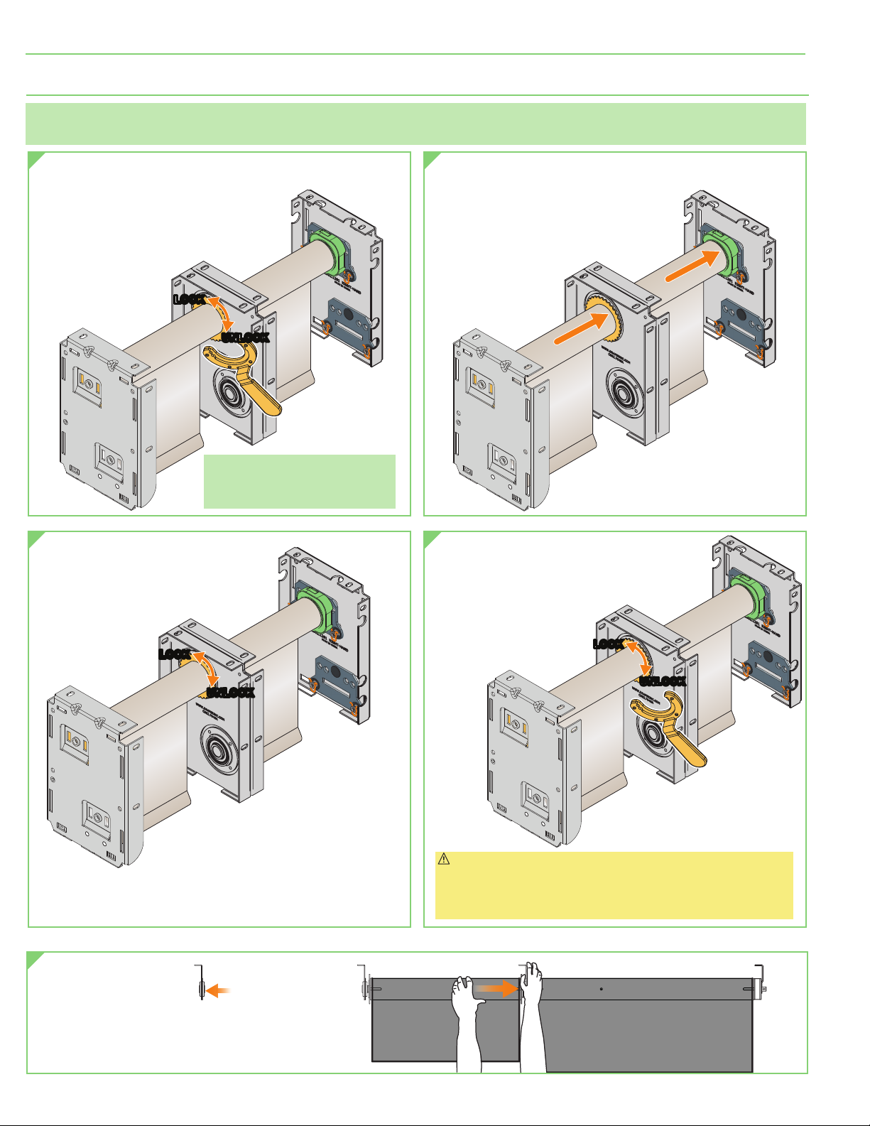
9.
Ensure the limit switches are pointed down or accessible when placing the
motor in brackets/endcaps.
10.
All motors should be tested and limits set using test cord before shades are
wired.
11.
Do not wire motors in parallel without written permission from Draper, Inc.
12.
During testing or operation, carefully watch the surrounding area for any
potential safety concerns including nearby persons or objects.
13.
After installation, the entire system, including all sensors, should be carefully
tested to ensure safe and normal operation. Extreme care should be taken
during testing to remain clear of moving parts to avoid possible injury.
14.
Operation of unit should be performed only by authorized and qualified
personnel, who have been trained in the safe and effective operation of the unit
and understand its safety features.
15.
The safety features of the unit , including sensors, should never be disabled,
bypassed, or overridden. The system should not be operated until all safety
features, including the sensors, are properly and completely installed,
calibrated, and tested.
16.
Unit may need to comply with local, state, or district rules and regulations, in
particular when installed in schools. All applicable rules and regulations should
be reviewed before installation and use.
17.
Failure to precisely follow installation guidelines invalidates all warranties.
18.
Custom products/installations may not be reflected in this manual. Call Draper,
Inc., if you have questions about the installation of custom products or any
questions about your installation.
Before Beginning Installation
1.
Look for any job site conditions that could interfere with installation or operation
of the system.
2.
Read carefully and be sure to understand all installation instructions and all
related operations manuals. These instructions are intended to serve as a guide
for the installer and owner. They should be followed closely and combined with
the expertise of experienced qualified installers. Draper, Inc., is not responsible
for improper installation, application, testing, or workmanship related to the
product at place of installation. Please retain all instructions for future use.
3.
Open cartons lengthwise.
4.
Locate and lay out all pieces.
5.
Inspect all boxes to ensure you have received the proper shade and parts.
Controls may be shipped separately, or in same carton as shade.
6.
If you have any difficulties with installing, servicing, or operating your shade, call
your dealer or Draper, Inc., 765-987-7999.
Important Safety Information Important Safety Information
PLEASE READ - Important Installation Information
Caution:
1.
Inspect all boxes to ensure you have received the proper shades and parts.
Controls may be shipped separately, or in same carton as shades.
2.
Open cartons lengthwise.
3.
Before mounting shades, verify measurements on label provided with shade,
and ensure unit is installed at correct width.
4.
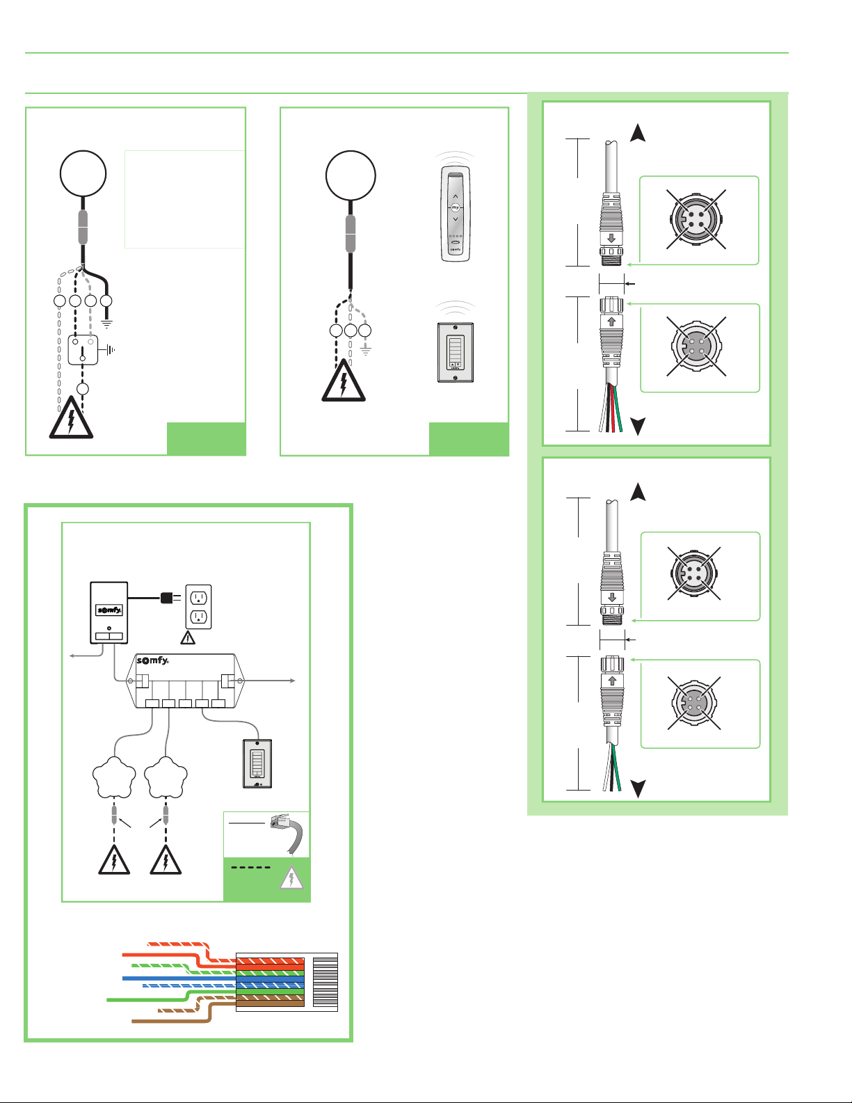
Before connecting switches, controls, or electrical, ensure that power is
turned OFF. Wiring indicated in diagram by dashed lines must be completed
by an electrician.
5.
Do not wire motors in parallel without written permission from Draper.
6.
All endcaps, fascia, pocket headbox, and other hardware must be installed
level. Shades must be level and square.
7.
Read the following installation guidelines thoroughly and follow them
carefully. Failure to do so may cause product to fall or otherwise fail,
and invalidates warranty.
8.
Installer is responsible for selecting mounting hardware appropriate for
site conditions.
PLEASE READ - Safety Information
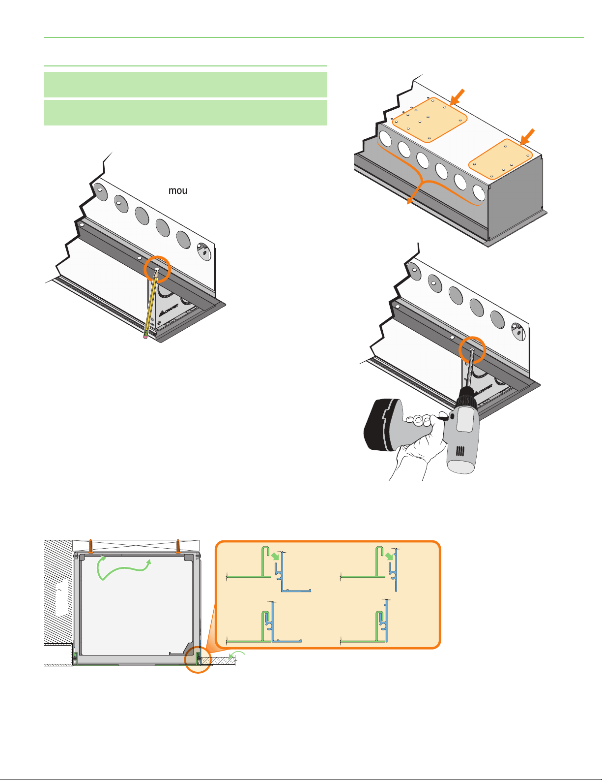
PLEASE READ - Field Adjustments
Each Draper Solar Control Shade is tested to ensure
proper operation. Even with this testing, some field
adjustments may be needed for telescoping.
If the shade is telescoping, place a piece of high
quality gaffer tape about 1"
(25mm)
wide on the
exposed roller
(where the fabric will cover it)
on the side
that the fabric will be drawn toward. For example: if
the fabric is tracking to the left, place the tape on the
right side.
PLEASE READ - Cleaning and Maintenance
Window covering products manufactured by Draper, when properly installed, should require no
operational maintenance or lubrication.
Most standard Draper fabrics may be cleaned at the window by vacuuming with a soft brush
attachment. They also may be cleaned by using a sponge or soft cloth and mild solution of warm soapy
water. A mild dishwashing liquid is recommended. A clean dry cloth is recommended for the metal finish.
Please Note: Exceptions are Flocké and Phifer SW7000®fabrics, which must be cleaned with a dry
art sponge.
(SheerWeave®is a registered trademark of Phifer®Incorporated. Flocké®is a registered trademark of
Mermet®Incorporated.)
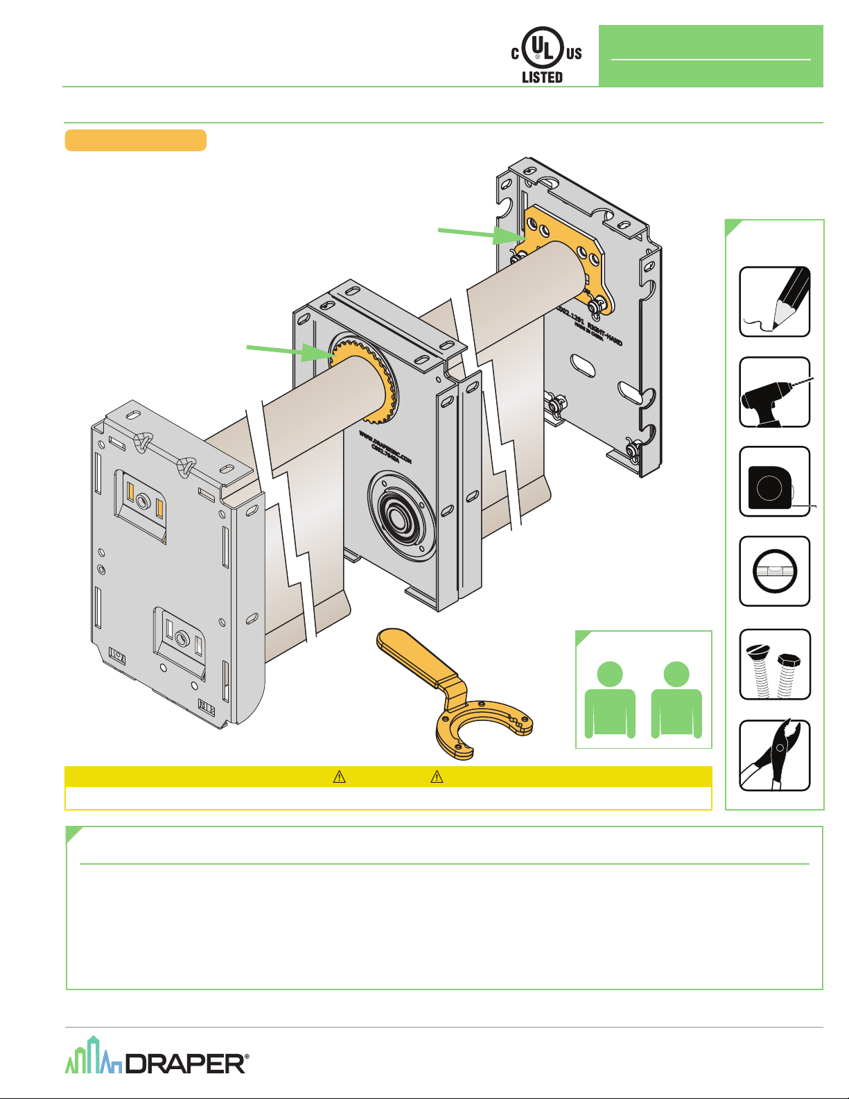
page 2 of 12
Dual Roller Coupled Motorized FlexShade®
(Standard Hardware)