Current Tools 750 Tweaker User manual

CURRENT TOOLS • P. O. BOX 17026 GREENVILLE, SC 29606
800.230.5421 or 864-721-4230 • FAX 864-721-4232
www.currenttools.com
Current Tools™ Mech anical Bender
Model 750 — ½" to 1"
RIGID and IMC conduit and schedule 40 Pipe
06/11 REV. 4
Operating, Maintenance, Safety
and Parts Manual
This manual is free of charge. All personnel who operate the
Mechanical Bender should have a copy of this manual and read
and understand its contents. To request a copy, call or write to
the address below.
Read and understand this material before
operating or servicing the Mechanical Bender.
Failure to understand how to safely operate
and service this unit could result in serious
injury or death.

Hazards or unsafe practices which, if not avoided, COULD result in
serious personal injury or death.
WARNING
Hazards or unsafe practices which, if not avoided, COULD result in
minor personal injury or property damage.
CAUTION
Immediate hazards which, if not avoided, WILL result in serious
personal injury or death.
DANGER
THIS SAFETY SYMBOL is used to call your attention to instructions
that concern your personal safety. It means: ATTENTION! BE AWARE!
THIS IS AN IMPORTANT SAFETY INSTRUCTION!
Read, understand, and follow these safety instructions. Failure to follow
these safety instructions may result in injury or death.
Safety Alert
Symbol
2
TABLE OF CONTENTS
Safety Alerts......................................... 2
Safety Information.................................... 3
Specifications ........................................ 4
Operating Instructions................................. 4
The TWEAKER™.......................................5
Maintenance......................................... 5
Stub Bending Information...............................6
Offset Bending Information..............................7
Exploded View ....................................... 8
Parts List — Model 750 Mechanical Bender. . . . . . . . . . . . . . . . 9
SAFETY ALERTS

RETAIN SAFETY INFORMATION
3
Keep hands and feet away from pinch points such as bending
shoe, ratchet handle and conduit when operating the bender.
Do NOT leave the ratchet handle in the up position.
The handle could fall and cause serious injury.
Do NOT force tool. If bend cannot be completed with the
5' section of 1" RIGID conduit used as a ratchet handle,
discontinue bend and determine cause before continuing.
Do NOT use a ratchet handle longer than 5' of 1"
RIGID conduit.
Do NOT stand on the bender. Serious injury could occur if
bender is tipped.
ALWAYS keep conduit under control when unloading. Conduit
not under control could injure the operator or others in the area.
ALWAYS inspect the bender before operating. Replace any
damaged, missing or worn parts.
WEAR approved safety glasses when using the bender.
Bender MUST be used on a firm, flat surface.
Do NOT use on an inclined surface.
ALWAYS keep the path of the bending conduit clear of
obstructions.
Keep firm hand pressure on the ratchet handle while bending.
The stored energy of bending conduit could cause the ratchet
handle to spring forward and strike operator or nearby personnel.
REMOVE the ratchet handle and conduit before moving
the bender.
Keep firm control of the bender T-handle when moving the
bender to avoid tipping over.
ONLY use the bender for its intended purpose. Only use the
bender to bend the specified types and sizes of conduit and pipe.
Bender is heavy and requires more than 1 person to lift.
WARNING
WARNING
CAUTION
CAUTION
CAUTION
WARNING
WARNING
CAUTION
CAUTION
CAUTION
CAUTION
CAUTION
CAUTION
CAUTION
This manual should be read and understood by all personnel who operate
or service this Mechanical Bender. Failure to understand how to safely
operate and service this unit could result in injury or death. This unit
should only be operated or serviced by qualified personnel.
IMPORTANT SAFETY INFORMATION
Follow ALL safety information provided by the manufacturer.

4
Figure 1
SPECIFICATIONS
Model No. 750
Capacity ½" to 1" RIGID and IMC conduit and
schedule 40 pipe
Overall Dimensions 48" L x 24 ½" W x 30" H
Weight 91 lbs.
OPERATING INSTRUCTIONS
1. Cut a 5' length of 1" RIGID conduit and insert it into the ratchet arm as
shown in Figure 1. This will serve as the ratchet handle.
2. Place the ratchet handle in the up position. This will release the ratchet pawl.
Rotate the bending shoe counter-clockwise. Then lower the ratchet handle.
3. Slide the conduit to be bent
over the corresponding size
on the conduit support unit,
through the shoe groove and
bending hook.
4. Place the bending mark on the
conduit in line with the front
edge of the bending hook.
See Figure C on page 6.
5. Raise the ratchet handle until
the pawl clicks. Push the ratchet
handle down. Repeat until you
have completed the desired bend.
6. To remove bent conduit, raise the ratchet handle to the up position.
Remove the ratchet handle from the ratchet arm and slide it into the pocket
provided on the bending shoe. While holding the bent conduit, slowly
rotate the bending shoe in the counter-clockwise direction and remove
the bent conduit.
7. Place the ratchet handle back into the ratchet arm and lower the ratchet
handle to the down position.
NOTE: Springback compensation is not calculated on the
bending degree indicator.
NOTE: When not in use the ratchet handle MUST remain in
the down position.

APPLY PRESSURE
TO CORRECT
OVERBEND
TWEAKER™
SHAFTS
5
Figure 2
THE TWEAKER™
The TWEAKER™ feature allows the operator to correct overbends of
3º or less on ½"– ¾"– 1" RIGID/IMC conduit or schedule 40 pipe.
To use the TWEAKER™:
1. Insert the conduit between the TWEAKER™ shafts shown on Figure 2.
2. Apply pressure to conduit as needed to correct overbend.
MAINTENANCE
Monthly: Apply multi-purpose grease at grease fitting.
See Item #27 on Exploded View on Page 8.
Monthly: Apply a few drops of oil into oil hole on bending shoe.
See Item #1 on Exploded View on Page 8.

6
Stub Dimensions Chart Figures are approximate.
Conduit Centerline Minimum Deduct
Size Bending Radius Stub Length Length
½" * 25/8" 6½" 5½"
¾" 45/8" 9½" 8½"
1" 57/8" 12" 11"
*½" conduit must be bent in the ¾" groove to make a bend with a radius greater
than 4". This will meet electrical code.
1" MINIMUM
BENDING
MARK
FIGURE C
STUB
LENGTH
FIGURE BFIGURE A
STUB
LENGTH
MARK
STUB
LENGTH
DEDUCT
LENGTH
BENDING
MARK
STUB BENDING INFORMATION
To locate bending marks for stubs:
1. Check the Stub Dimensions Chart (below) for Minimum Stub Length. The
stub being bent must be equal to or longer than the Minimum Stub Length.
2. Measure and mark the stub length required on the conduit. This is the stub
length mark. See Figure A. Locate the Deduct Length on the Stub Dimensions
Chart (below). Deduct this length from the stub length mark and make a
second mark. This is the bending mark. See Figure A.
3. Put the conduit in the bender and place the bending mark in line with
the front edge of the shoe hook. The conduit must extend at least 1" past
the shoe hook. See Figure C. Complete the bend.
FIGURE A FIGURE B FIGURE C

7
MARK #2
MARK #3
MARK #1
DEDUCT
LENGTH
CENTER-TO-CENTER LENGTH
FIGURE 1 FIGURE 2
OFFSET
HEIGHT ANGLE
START OF BEND
Center-to-Center Chart Figures are approximate.
Offset Height 2 4 6 8 10 12 14 16 18 20 22
Max Conduit Size
¾" 1"
15˚
Center-to-Center
7¾" 157/16" 233/16" 3015/16" 385/8" 463/8" 541/16" 6113/16" 699/16" 77¼" 85"
Max Conduit Size
¾" 1"
30˚
Center-to-Center
8" 12" 16" 20" 24" 28" 32" 36" 40" 44"
Max Conduit Size
½" 1"
45˚
Center-to-Center
8½" 1115/16" 141/8" 1615/16" 1913/16" 225/8" 25 7/16" 28¼" 311/8"
To locate the center-to-center distance of offset bending marks other than those listed in the above chart,
use the following multipliers. Multiply the height of offset desired by 3.86 on 15˚ bends, 2 on 30˚ bends, and
1.4 on 45˚ bends.
Deduct Chart
Conduit Deduct
Size Length
½" 2½"
¾" 3¼"
1" 4¼"
Figures are approximate.
OFFSET BENDING INFORMATION
To mark conduit for offsets:
1. Measure distance from end of conduit to start of first bend and mark
conduit. This is mark #1. See Figure 1 and 2.
2. Refer to Deduct Chart and deduct this length from mark #1 and place
mark #2 on conduit. See Figure 1.
3. Measure the height of the obstacle. This is the offset height. Refer to the
Center-to-Center Chart to locate the next mark. Measure the center-to-center
distance from mark #2 and place mark #3 on conduit. See Figure 1.
4. Layout of bends is now complete. Next, place mark #2 in line with front
edge of shoe hook and make first bend. Note: Conduit must extend
at least 1" past front edge of shoe hook. See Figure C on page 6.
5. Rotate conduit in the bender 180˚.
Place mark #3 in line with front
edge of shoe hook and complete
second bend.

8
EXPLODED VIEW — Model 750 Mechanical Bender
14
29
13
3
27
25
26
24
2
23
11
10
6
15
21
22
OIL
HOLE
4
20 1
17
12
16
19
5
7
8
18
9
33

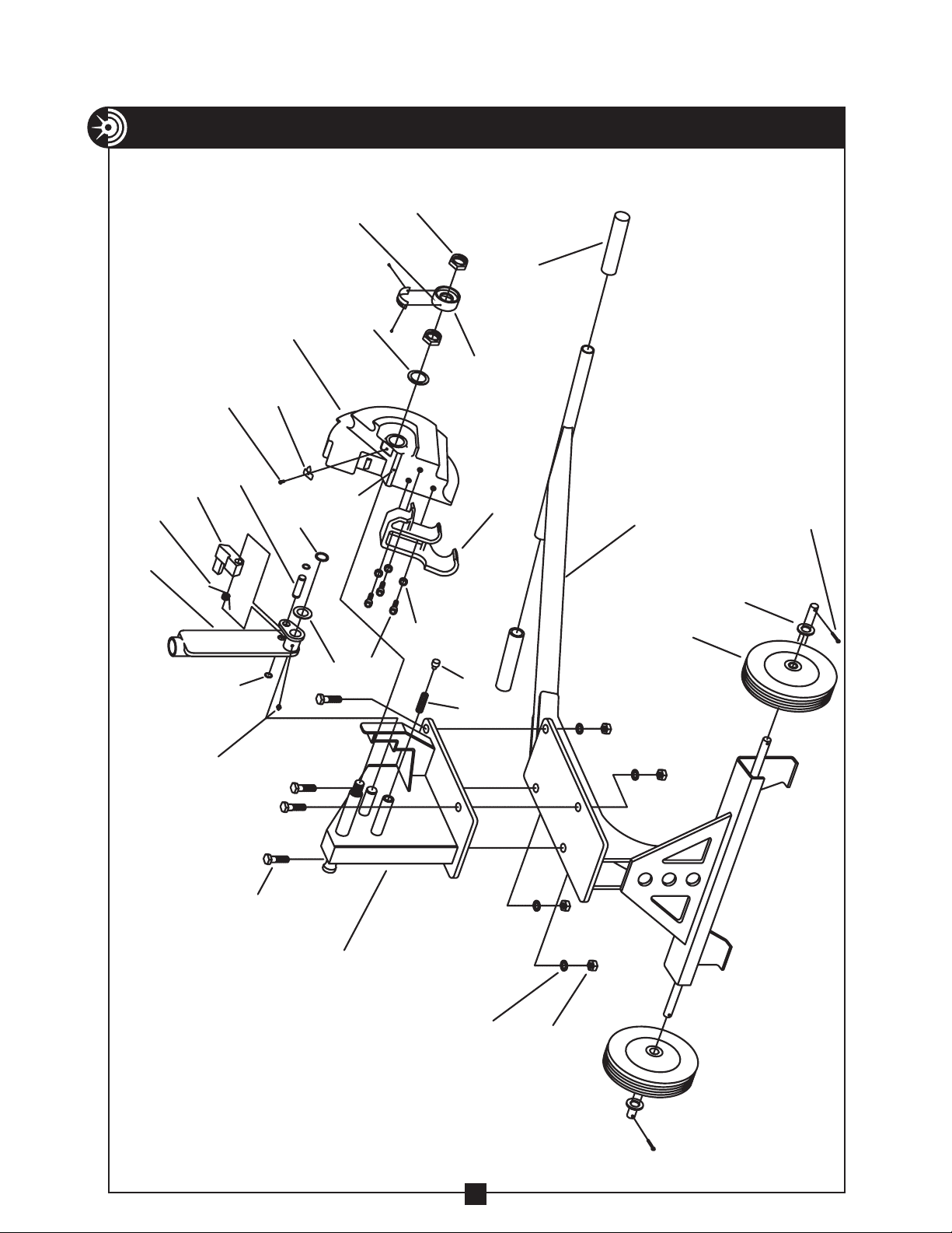
PARTS LIST — Model 750 Mechanical Bender
ITEM # PART # QTY DESCRIPTION
........1 ..............BENDING SHOE
........1 .............BENDER HOUSING
........1 ..............ROLLING STAND
. . . . . . . . 1 . . . . . . . . . . .WASHER – FLAT 7/8 SAE
........1 .............. RATCHET ARM
........1 ..............BENDING HOOK
........1 ..............RATCHET PAWL
........1 ...............RATCHET PIN
1 . . . . . . . . . . . 750-1. .
2 . . . . . . . . . . 750-418.
3 . . . . . . . . . . 750-668
4 . . . . . . . . . . . 750-13 .
5 . . . . . . . . . . 750-335.
6 . . . . . . . . . . . 750-15 .
7 . . . . . . . . . . 750-330.
8 . . . . . . . . . . 750-347.
9 . . . . . . . . . . . 750-10 . . . . . . . . . 1 . . . . . . . . . . . . . TORSION SPRING
10........... 750-9..........1 .............PRESSURE SPRING
11.......... 750-294.........1 ..............PRESSURE PLUG
12........... 504-1..........2 ...................GRIP
13...........509-13 .........2 ..................WHEEL
14...........77-016 .........2 ................COTTER PIN
15. . . . . . . . . . 750-348. . . . . . . . . 1 . . . . . . . . BENDING DEGREE INDICATOR
16...........750-18 .........2 ........ 7/8"-9 HEX LOCK NUTS (THIN)
17. . . . . . . . . . 750-382. . . . . . . . . 1 . . . . . . . . . . . . INDICATOR ARROW
18 . . . . . . . . . . . 750-20. . . . . . . . . . 1 . . . . . . . . . . ¼-20 X ½" HEX HD SCREW
19. . . . . . . . . . . 750-21 . . . . . . . . . 2 . . . . . . . . . . . .RETAINING RING – ½"
20. . . . . . . . . . . 750-22 . . . . . . . . . 1 . . . . . . . . . . . . RETAINING RING – 1"
21.......... 750-394.........1 .................WASHER
22...........750-25 .........3 ......... 3/8 -16 X 1" HEX HD SCREW
23...........452-27 .........3 .............3/8" LOCK WASHER
24...........281-2C.........4 .............½" LOCK WASHER
25. . . . . . . . . . . 281-1F . . . . . . . . . 4 . . . . . . . . ½"-13 X 1½" HEX CAP SCREW
26...........280-2G.........4 .............. ½"-13 HEX NUT
27........... 88-39..........1 ..............GREASE FITTING
28. . . . . . . . . . . 750-M . . . . . . . . . 1 . . . . . . . . . .DECAL SET (NOT SHOWN)
29. . . . . . . . . . . 77-017 . . . . . . . . . 2 . . . . . . . . . . .WASHER – FLAT, 3⁄4 SAE
9
Table of contents
Other Current Tools Construction Equipment manuals
Popular Construction Equipment manuals by other brands

Greenlee
Greenlee Cam Track 881 instruction manual

Woods
Woods RB72.50 Operator's manual

HYVA
HYVA Amco Veba 946 WARNING, OPERATING AND MAINTENANCE MANUAL

Mega
Mega DIN-2440 Operation and maintenance instructions

Graco
Graco LineLazer 3000 Instructions-parts list

Epiroc
Epiroc EC Series Safety and operating instructions

nokka
nokka 2051P Installation, operation and maintenance manual

stellar labs
stellar labs Model 5521 owner's manual

MSI
MSI MSI-9300HT Setup exit guide supplement

Pentair
Pentair HYPRO Cleanload Max 3378 Series Original instruction manual

Denzel
Denzel DCM-125 user manual

MBM
MBM SCREEDEMON EWS500 Operator's safety and service manual