Current Daintree WOS2-WM Service manual

The Daintree wall mounted Wireless Occupancy Sensor (WOS2-WM) operates seamlessly within the Daintree wireless
lighting control platform. The WOS2-WM is a battery-powered occupancy sensor utilizing passive infrared (PIR) sensing
technology to detect movement. As part of the Daintree sensor product line and using open, standards based ZigBee wireless
communications, the WOS2-WM reports real-time occupancy events to turn on lights or keep them on when movement is
detected,and turn off lights when a space is vacant. The sensor’s off-delay timer is user-configurable from any location using
Daintree’s ControlScope Manager (CSM) web application, eliminating the need for on-site, manual sensor adjustment.
Installation Process
•Keep the sensor lens clean. Avoid touching the
sensor lens.
•After first-time installation or reinstallation of a new
battery, allow up to three minutes for initalization.
1. Determine the mounting location
for the sensor based on the desired
occupancy coverage. See Placement
for details.
2. Attach the mounting base to the
wall in the specified location.
3. Record the sensor’s IEEE address and
location on the facility floor plan.
4. Install the batteries in the orientation (+ - ) shown on
the bottom of the battery compartments.
5. Attach the sensor’s main unit to the ball socket on the
mounting base. Adjust the angle of the sensor, then hand-
tighten the collar to secure the angle.
6.After the batteries have been installed for at least
3 minutes, initiate the Installation Test Mode: Momentarily
press the Utility button. The green LED flashes once, then
the red LED flashes each time the sensor detects motion.
(The test modetimes out after 5 minutes.)
A. Walk test the sensor. Walk outside the coverage
area and wait for the red LED to stop flashing.
Step inside the desired coverage area and observe
the red LED.
B. Repeat from various positions in the coverage area.
C. If necessary, adjust the sensor as described in
Adjustments: PIR Sensitivity. Repeat the walk test.
D. If you do not observe the proper behavior, see
Troubleshooting.
Wireless Occupancy Sensor, Wall Mount
(WOS2-WM)
Installation Instructions
Counter-clockwise to
Loosen or Remove
Clockwise to
Tighten
Infrared
Detec on &
Test Mode LED
(red)
Network LED
(green)
Counter-clockwise to
Loosen or Remove
Clockwise to
Tighten
Infrared
Detec on &
Test Mode LED
(red)
Network LED
(green)
Counter-clockwise to
Loosen or Remove
Clockwise to
Tighten
Infrared
Detec on &
Test Mode LED
(red)
Network LED
(green)
1
DT106 (Rev. 2.5.18)
7.Exit Installation Test Mode. Momentarily press the
Utility button again, or wait 5 minutes for the mode to
time out.
8.The sensor attempts to join a ZigBee network for
up to 30 seconds. If it is able to join, the Network LED
turns on solid for 10 seconds. If it is unable to join, it
automatically retries every 15 minutes until it succeeds
in joining a network. Note, the sensor will not be able
to join a network until a Wireless Area Controller (WAC)
is commissioned. See LED Operation and Joining the
ZigBee Network.
LED Operation
* A network join can be retriggered manually at any time
using one of the following methods:
•Reset to factory defaults: This causes the device to
leave any network to which it is currently joined.
Following the reset, the device attempts to join a
network. Press and hold the Utility button for
5 seconds. Release the button when the Network
LED begins to flash rapidly.
•Activate device: Press and hold the Utility button
for 2 seconds. If the device is already joined to a
network, the Network LED flashes twice. If the
device is not joined to a network, the Network
LED flashes rapidly and the device will attempt to
join a network.
For more information about configuring the lighting
control network, see the instructions and on-line help
provided with the CSM application.
Joining the Zigbee Network
After successfully completing the Installation Test the
occupancy sensor is ready to communicate with the
Daintree Wireless Area Controller (WAC) and the Daintree
CSM web-based lighting management user interface.
For more information about configuring the lighting
control network, see the instructions and on-line help
provided with the CSM application.
Wireless Occupancy Sensor, Wall
Mount (WOS2-WM)
Green LED: Network
Indicator Description
Rapid flash (12times
per second) for up to 30
seconds
Device is trying to join ZigBee network. If it
fails to join, it will retry after 15 minutes.*
Solid for 10 seconds Device successfully joined a ZigBee
network.
Flashes once Utility button was pressed to initiate
Installation Test Mode.
Flashes twice Utility button was pressed for 2 seconds
and the device is currently joined to a
network.
On for 2 seconds every
30 seconds The batteries are low; replace the
batteries. Also, see alert on CSM.
Red LED: Installation Test
Mode, Motion Description
While unit is in
Installation Test Mode,
Flashes
The red LED flashes each time sensor
detects occupancy. Test mode times out
after 5 minutes.
Off
Normal operation: either not detecting
occupancy, or detected occupancy and
in Off Delay. LED turns on with initial
occupancy.
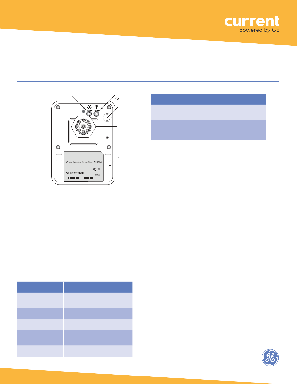
PIR
Daylight Hold-Off
Compartment
Cover (press
arrows then
slide down
to open)
Swivel
Mount
Collar
Wireless Occupancy Sensor, Model: WOS2-WM
Power Supply: Battery ER14505 AA 3.6V (2)
FCC ID:NRH-ZB-Z100B
IC: 8984A-Z100B
ICES/NMB-003CLASS B
FORINDOOR USE ONLY
20120412
IEEE Address: 00137A000000-0000
2

Wireless Occupancy Sensor, Wall
Mount (WOS2-WM)
Placement
The PIR sensor can only be installed indoors. It is
extremely important to select the appropriate installation
location to avoid false occupancy reporting while
obtaining the best sensitivity. A proper installation should
meet the following conditions:
•The PIR sensor is typically mounted 6.5’ to 10’
(2m to 3m) from the floor, with a 15 degree vertical
tilt. The height, tilt, and angle of the installation
affects the coverage area.
•The PIR sensor must be 4’ to 6’ away from hot
or cold sources such as heat or air conditioner
vents, refrigerators, stoves, and so on. The PIR
sensor should not be installed in places with strong
air flows.
•The PIR sensor must have clear line of sight to the
coverage area. It may not detect a human body
if it is blocked by furniture, fixtures, large plants,
glass, curtains, and so on.
•Install the detector securely to the ceiling or wall
to minimize sensor vibration. The PIR sensor should
not be installed on doors or windows, nor exposed
to direct sunlight. The resulting hot air and/or
motion can cause false activation.
•The effectiveness of the PIR sensor is highly related
to the direction of human motion.
Installation Height 6.5’ to 10’ (2m to 3m) from floor
Installation Angle 15° tilt toward floor
Detection Angle 110°
Detection Range up to 36’ (11m)
WOS2-WM-W (wide-angle)
Thesensor
is most
responsive
when
crossing the
field of view:
Thesensor
is less
responsive
to radial
movement:
Top View
36’
(11m)
36’
(11m)
09.8’
(3m)
9.8’
(3m)
19.6’
(6m)
29.5’
(9m)
19.6’
(6m)
29.5’
(9m)
Sensor mounted at 9.8’ (3m) height from floor, 15
9.8’
(3m)
19.6’
(6m)
29.5’
(9m)
(6(6
6.5’
(2m)
0
3.28’
(1m)
9.8’
(3m)
36’
(11m)
9.8’
(3m)
19.6’
(6m)
29.5’
(9m)
3.28’
(1m)
6.5’
(2m)
13.1’
(4m)
16.4’
(5m)
22.8’
(7m)
26.2’
(8m)
32.8’
(10m)
Side View Sensor mounted at 9.8’ (3m) height from floor, 15
9.8’
(3m)
29.52’
(9m)
59.0’
18m)
88.6’
(27m)
9.8’
(3m)
19.7’
(6m)
39.4’
(12m)
53.8’
(15m)
68.9’
(21m)
78.7’
(24m)
98.4’
(30m)
9.8’
(3m)
0
10˚
15˚
Top ViewSensor mounted at 9.8’ (3m) height from floor, 15
30˚
0
0
9.8’
(3m)
101.68’
(31m)
29.52’
(9m)
59.0’
18m)
88.6’
(27m)
9.8’
(3m)
19.7’
(6m)
39.4’
(12m)
53.8’
(15m)
68.9’
(21m)
78.7’
(24m)
98.4’
(30m)
Side View Sensor mounted at 9.8’ (3m) height from floor, 15
More
Responsive
Less
Responsive
Thesensor
is most
responsive
when
crossing the
field of view:
Thesensor
is less
responsive
to radial
movement:
Top View
36’
(11m)
36’
(11m)
09.8’
(3m)
9.8’
(3m)
19.6’
(6m)
29.5’
(9m)
19.6’
(6m)
29.5’
(9m)
Sensor mounted at 9.8’ (3m) height from floor, 15
9.8’
(3m)
19.6’
(6m)
29.5’
(9m)
(6
(6
6.5’
(2m)
0
3.28’
(1m)
9.8’
(3m)
36’
(11m)
9.8’
(3m)
19.6’
(6m)
29.5’
(9m)
3.28’
(1m)
6.5’
(2m)
13.1’
(4m)
16.4’
(5m)
22.8’
(7m)
26.2’
(8m)
32.8’
(10m)
Side View Sensor mounted at 9.8’ (3m) height from floor, 15
9.8’
(3m)
29.52’
(9m)
59.0’
18m)
88.6’
(27m)
9.8’
(3m)
19.7’
(6m)
39.4’
(12m)
53.8’
(15m)
68.9’
(21m)
78.7’
(24m)
98.4’
(30m)
9.8’
(3m)
0
10˚
15˚
Top ViewSensor mounted at 9.8’ (3m) height from floor, 15
30˚
0
0
9.8’
(3m)
101.68’
(31m)
29.52’
(9m)
59.0’
18m)
88.6’
(27m)
9.8’
(3m)
19.7’
(6m)
39.4’
(12m)
53.8’
(15m)
68.9’
(21m)
78.7’
(24m)
98.4’
(30m)
Side View Sensor mounted at 9.8’ (3m) height from floor, 15
More
Responsive
Less
Responsive
Installation Height 6.5’ to 7.2’ (2m to 2.2m) from floor
Installation Angle 15° tilt toward floor
Detection Angle 20° / 30 meters
Detection Range 6.5’ to 98.4’ (2m to 30m)
WOS2-WM-L (long range)
Thesensor
is most
responsive
when
crossing the
field of view:
Thesensor
is less
responsive
to radial
movement:
Top View
36’
(11m)
36’
(11m)
09.8’
(3m)
9.8’
(3m)
19.6’
(6m)
29.5’
(9m)
19.6’
(6m)
29.5’
(9m)
Sensor mounted at 9.8’ (3m) height from floor, 15
9.8’
(3m)
19.6’
(6m)
29.5’
(9m)
(6
(6
6.5’
(2m)
0
3.28’
(1m)
9.8’
(3m)
36’
(11m)
9.8’
(3m)
19.6’
(6m)
29.5’
(9m)
3.28’
(1m)
6.5’
(2m)
13.1’
(4m)
16.4’
(5m)
22.8’
(7m)
26.2’
(8m)
32.8’
(10m)
Side View Sensor mounted at 9.8’ (3m) height from floor, 15
9.8’
(3m)
29.52’
(9m)
59.0’
18m)
88.6’
(27m)
9.8’
(3m)
19.7’
(6m)
39.4’
(12m)
53.8’
(15m)
68.9’
(21m)
78.7’
(24m)
98.4’
(30m)
9.8’
(3m)
0
10˚
15˚
Top ViewSensor mounted at 9.8’ (3m) height from floor, 15
30˚
0
0
9.8’
(3m)
101.68’
(31m)
29.52’
(9m)
59.0’
18m)
88.6’
(27m)
9.8’
(3m)
19.7’
(6m)
39.4’
(12m)
53.8’
(15m)
68.9’
(21m)
78.7’
(24m)
98.4’
(30m)
Side View Sensor mounted at 9.8’ (3m) height from floor, 15
More
Responsive
Less
Responsive
3
Wireless Occupancy Sensor, Wall
Mount (WOS2-WM)
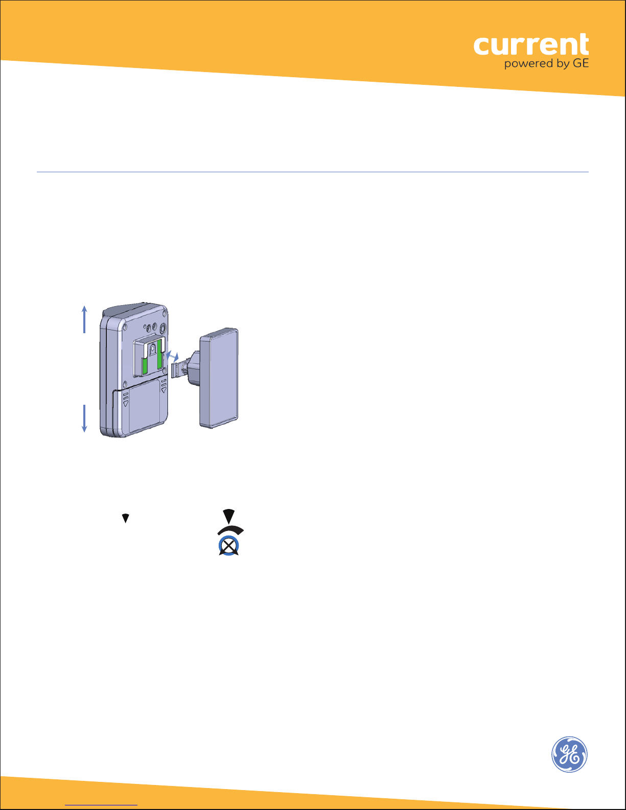
Adjustments
Two trimpots on the back of the sensor are used to adjust
the Daylight Hold-Off threshold and PIR motion sensor
sensitivity. For easier access to the trimpots after the
sensor has been mounted, remove the sensor from the
mounting bracket.
Remove
sensor
from
bracket
Attach
sensor
to
bracket
Troubleshooting
No LEDs turn on when I press the Utiity button.
•Check battery installation.
•Make sure batteries are oriented (+ -) correctly.
The red Infrared Detection LED does not activate
when walking through the coverage area while in
Installation Test mode.
•Check to see if the red LED turns on when you
wave your hand directly in front of the lens.
– If the red LED turns on, adjust the PIR
Sensitivity trimpot clockwise to increase
sensitivity. Check for objects or barriers
obstructing the sensor’s view of the
coverage area.
– If the red LED does not turn on, the
Installation Test mode may have timed out.
Restart the Installation Test mode by
momentarily pressing the Utility button.
The green LED turns on briefly, then the red
LED flashes with each detection. Installation
Test mode times out in 5 minutes.
The red LED flashes when nobody is moving in the
coverage area.
•
Adjust the PIR senstivity trimpot counter-clockwise
to reduce sensitivity. Repeat the walk test.
•Check for sources of hot airflow in the
coverage area.
•Review the Placement guidelines and eliminate
false trigger sources.
If lights do not turn Off after the WOS2-CM has
Joined the ZigBee network:
•Check the “Off delay” for the zone in the
Daintree CSM.
•Check for other CSM scheduled events or
manual overrides that may be keeping the
lights On.
Use caution when adjusting the trimpots. Do not use
excess force, as this will damage the unit. Stop turning
the trimpot when you feel resistance.
PIR Sensitivity
Turn the trimpot clockwise
to increase sensitivity. Turn the
trimpot counter-clockwise to
decrease sensitivity.
To test the daylight hold-off after the installation is
complete and the sensor has been added to CSM:
1.Ensure that CSM’s control strategy for this zone makes
use of occupancy sensors and has the ‘Enable Daylight
hold-off ’ check box selected.
2.Wait until vacancy is detected and the lights turn off.
3. Trigger occupancy while the light level is below the
selected threshold. The lights should turn on.
Trigger occupancy while the light level is above the
selected threshold. The lights should remain off.
Minimum
(counter-
clockwise)
Maximum
(clockwise)
Minimum
(counter-
clockwise)
Maximum
(clockwise, disable
daylight hold-off)
4

Specifications
Power Supply (2) Lithium-thionyl chloride batteries
(Li-SOCl2) AA 3.6V (included)
Battery Life 5 years (normal operation)
Radio Properties 2.4 GHz, +7dBm transmit power
Sensor Coverage
(maximum) 110°, 11 m/36 (WOS2-WM-W)
20°, 30 m/98 (WOS2-WM-L)
Off-Delay Timer 30 seconds (fixed), additional delay time
configurable in CSM
Dimensions 3.6” W x 2.8” H x 3” D
(92mm W x 70mm H x 77mm D) Weight
(without battery): 3.32 oz. (94g)
Wireless Occupancy Sensor, Wall
Mount (WOS2-WM)
FCC warning message
This equipment has been tested and found to comply
with the limits for a Class B digital device, pursuant to
Part 15 of the FCC Rules. These limits are designed
to provide reasonable protection against harmful
interference in a residential installation. This equipment
generates, uses and radiates radio frequency energy
and, if not installed and used in accordance with the
instructions, may cause harmful interference to radio
communications. However, there is no guarantee that
interference will not occur in a particular installation.
If this equipment does cause harmful interference to
radio or television reception, which can be determined
by turning the equipment off and on, the user is
encouraged to try to correct the interference by one
or more of the following measures:
•Reorient or relocate the receiving antenna;
•Increase the separation between the equipment
and receiver;
•Connect the equipment into an outlet on a
circuit different from that to which the receiver
is connected;
•Consult the dealer or an experienced radio/TV
technician for help.
5
Industry Canada (IC) Warning
Message
Product complies with Part 15 of the FCC Rules.
Operation is subject to the following two conditions: (1)
This device may not cause harmful interference, and (2)
This device must accept any interference received,
including interference that may cause undesired
operation.
Call 1 888 694 3533 products.currentbyge.com
GE is a trademark of the General Electric Company. All other trademarks are the property of their respective owners.
Information provided is subject to change without notice. All values are design or typical values when measured
under laboratory conditions. Current and GE Lighting are businesses of the General Electric Company. © 2017 GE
Operating Environment 14°F to +122°F (-10°C to 50°C)
Indoor use only
Compliance FCC Part 15B, FCC ID: NRH-ZB-Z100B
ICES/NMB-003 Class B, IC: 8984A-Z100B
(2) Screw holes on swivel mount bracket;
wall (or ceiling) mount
Mounting
Table of contents
Other Current Accessories manuals


Popular Accessories manuals by other brands


Asus
Asus MW Series user manual

BS Bodensteckdosen Systemtechnik
BS Bodensteckdosen Systemtechnik 85 E Series instruction manual

nedis
nedis PEBL120CWT2 quick start guide

LEGRAND
LEGRAND Wattstopper LMLS-400 installation instructions

Comunello Automation
Comunello Automation DART SLIM Installation and user manual

Dimavery
Dimavery LP-1 user manual