Curt Manufacturing Inc., warrants this product to be free of defects in material and/or workmanship at the time of retail purchase by the original purchaser. If the product is found to be defective,
Curt Manufacturing Inc., may repair or replace the product, at their option, when the product is returned, prepaid, with proof of purchase. Alteration to, misuse of, or improper installation of
this product voids the warranty. Curt Manufacturing Inc.'s liability is limited to repair or replacement of products found to be defective, and specifically excludes liability for incidental or
consequential loss or damage.
60644 SUBKIT
8/22/2013
**DO NOT EXCEED RECOMMENDED VEHICLE TOWING WEIGHT!**
DRIVER SIDE WHEEL WELL
WARNING!! BRAKE, FUEL, AND ELECTRICAL LINES MAY NEED TO BE LOOSENED OR REPOSITIONED TO PROVIDE CLEARANCE FOR NEW HARDWARE.
ALL MODELS REQUIRE MODIFICATION OR REMOVAL OF HEAT SHIELDS. ON SHORT BED MODELS, CHECK FOR ADEQUATE TURNING CLEARANCE. BETWEEN
THE FRONT OF ALL TRAILERS AND THE TRUCK CAB.
BEFORE INSTALLING
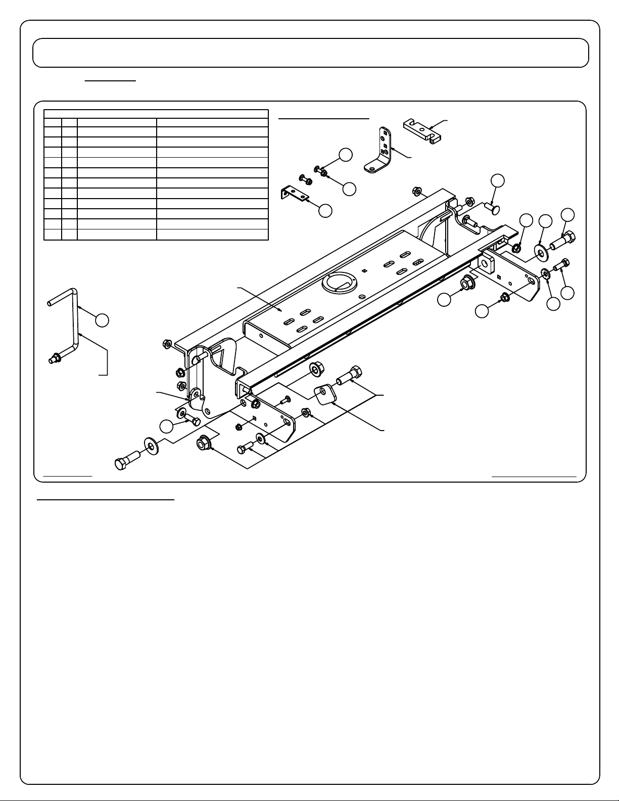
For ease of installation the use of Curt Part # C-606 (Gooseneck Install Tool) is recommended. A lifting device, such as an
engine hoist, or cable come-a-long can also be used to lift the center section of the hitch into place. Use of one of these
tools will be especially helpful if the truck bed has been distorted downward from heavy use. After the hole is drilled in the
truck bed the rope or chain loop can be lowered through the drilled hole and attached to the center of the gooseneck hitch.
The gooseneck can then be raised so that the center ring protrudes through the bed floor. Maintaining the upward
pressure from the lifting device onto the gooseneck hitch will ease the process of attaching the gooseneck center section
to the crossarms. Remove lifting device before torquing hardware.
1. Mark the location for the hole in the truck bed. Measure from the tail gate end of the truck bed. Do this by hooking a tape
measure over the back of the truck box and marking the correct location. (NOTE: DO NOT MEASURE FROM EDGE OF
TAILGATE) Next, mark the center between the wheel wells. This marks the center point for the drill hole. This
hole location is critical for the correct installation of this hitch. Measure, mark, and saw carefully. This location will put
the ball 4"- 6" in front of the axle.
NOTE: If truck has a plastic bed liner, you may drill through both, but it is more difficult to accurately locate the midpoint
between the wells, and to keep the bed liner from moving while cutting the hole. Make a 4"(3 5/8" for the C-640)
hole at this location using a 4"(or 3 5/8") hole saw or by making a 4"(or 3 5/8") circle and cutting it out with a saber
saw equipped with a metal cutting blade.
2. The exhaust will need to be lowered on 2005 and newer trucks equiped with a
diesel engine. First remove the exhaust hanger located behind the rear tire on
the passenger side. This will be re-installed later.
3. Remove the heat shield which is located under the truck bed above the rear axle.
4. On 2004 and older trucks, the emergency brake cable located on the outside of the
driver's side frame will need to be relocated. Knock the mounting stud out of the
frame with a hammer and punch and discard. A 5/16" relocating bolt is included in
the kit and will be installed after the sideplates are installed.
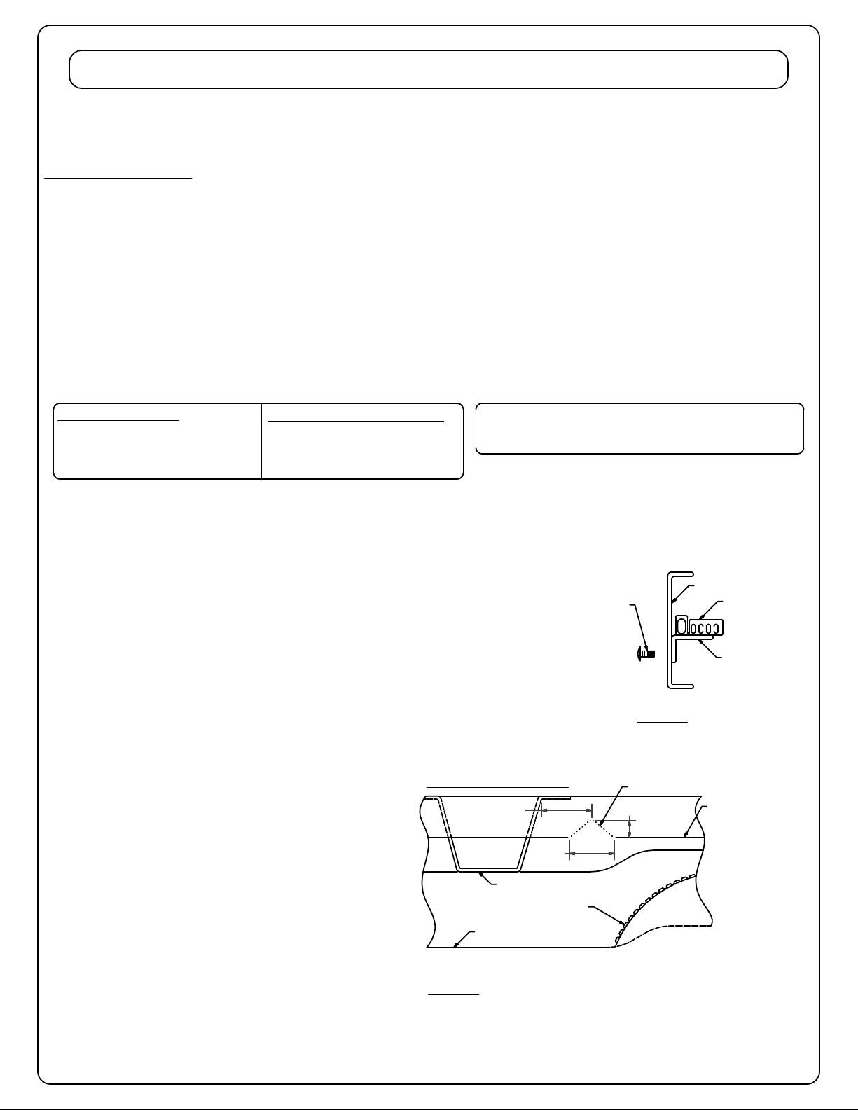
On gasoline engine trucks, it may be necessary
to relocate a fuel line bracket. If the oval hole in
the driver's side framejust above the axle is
partially blocked, you will need to relocate the
bracket blocking the oval by removing the bracket
from the frame, rotating it 90°, then installing the
supplied fuel line bracket in the bolt kit with a 5/16"
carriage bolt. See FIGURE A
5. Some truck models will allow the crossarms to
slide between the frame and bed without
modification. If this is not possible, cut a small
notch in the flange on driver's side of the truck
as shown in FIGURE B. Locate the front bed
crossmember in the wheel well and measure
back from that.
FIGURE A
FIGURE B
VEHICLE FRAME RAIL
SUPPLIED FUEL
LINE BRACKET
MANUFACTURER'S
FUEL LINE BRACKET
SUPPLIED 5/16"
CARRIAGE BOLT
**IMPORTANT NOTE**
If truck bed has spray on bed liner, add 1/8" to 3/16"
when measuring location of center hole.
Page 1
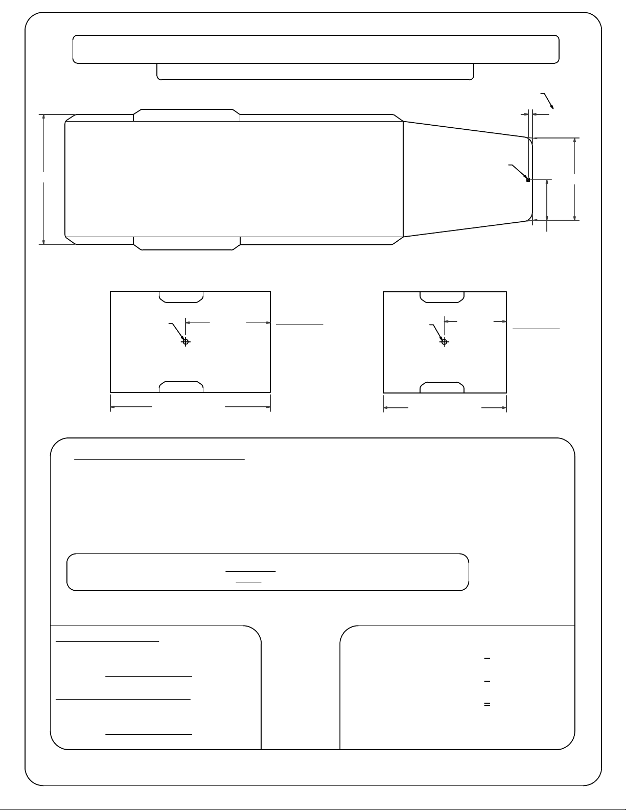
99-CURRENT FORD 3/4 & 1 TON SUPER DUTY, 08' F-450
(WITH OR WITHOUT AFTERMARKET AIR BAG OVERLOADS)
WARNING!! ON TWO WHEEL DRIVE TRUCKS A CLEARANCE CHECK MUST BE PERFORMED WHEN TRUCK IS LOADED
AND UNLOADED TO VERIFY THE INVERTED BALL WILL NOT INTERFERE WITH THE TOP OF THE DIFFERENTIAL
1999-2010 MODELS:
LONG AND SHORT BED = 48 1/4"
(CENTER CYLINDER IN GOOSENECK OFFSET
TOWARDS FRONT OF VEHICLE)
2011 TO CURRENT MODELS:
LONG AND SHORT BED = 46"
(CENTER CYLINDER IN GOOSENECK OFFSET
TOWARDS REAR OF VEHICLE)
FLANGE BELOW BED
FLOOR ON DRIVER
SIDE WHEEL WELL
FRONT BED CROSSMEMBER
VEHICLE FRAME RAIL
7/8"
3/8"
1 1/2"
REAR DRIVER SIDE TIRE
APPROXIMATE TRIM LINE