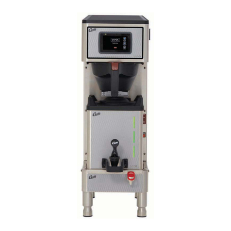
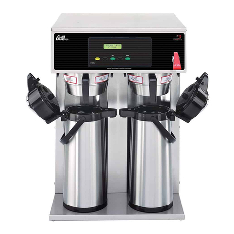
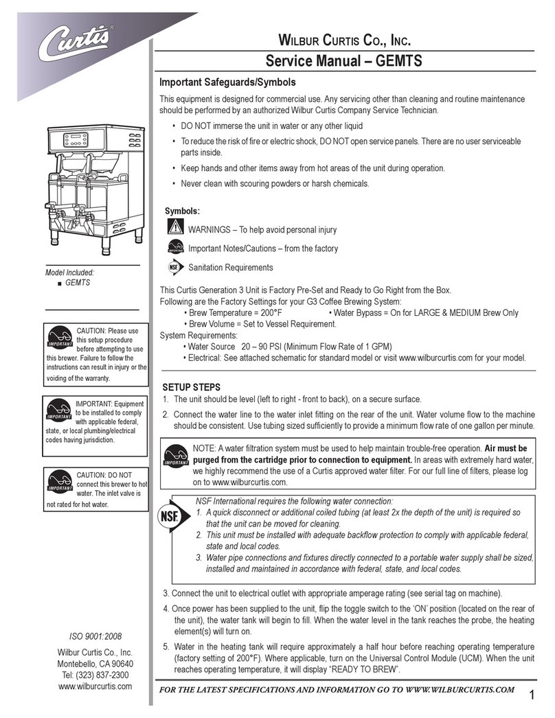
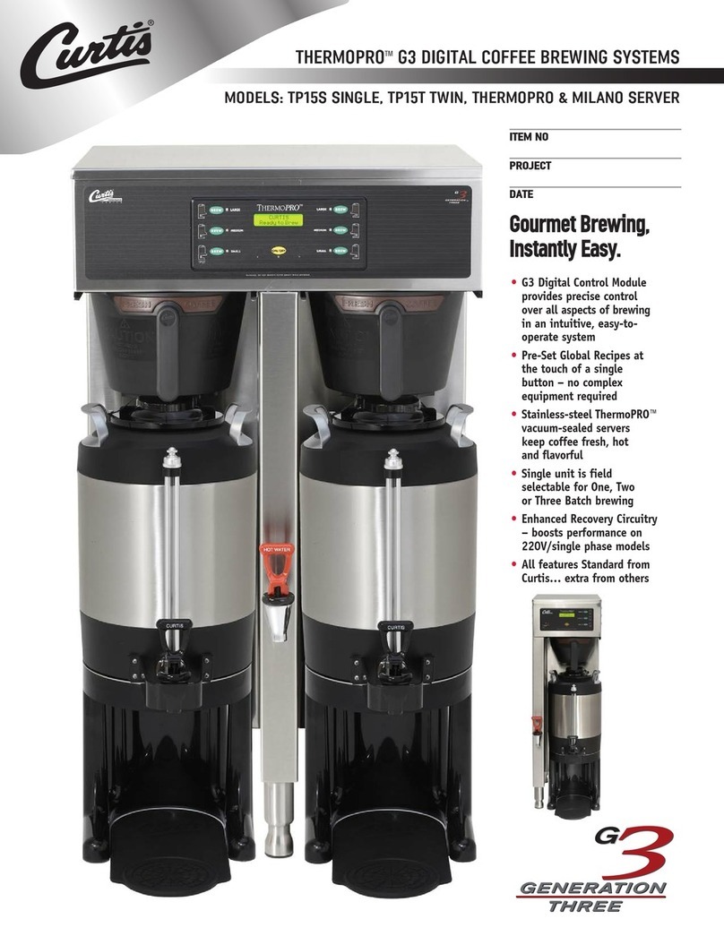
Curtis G4GEMT User manual

1
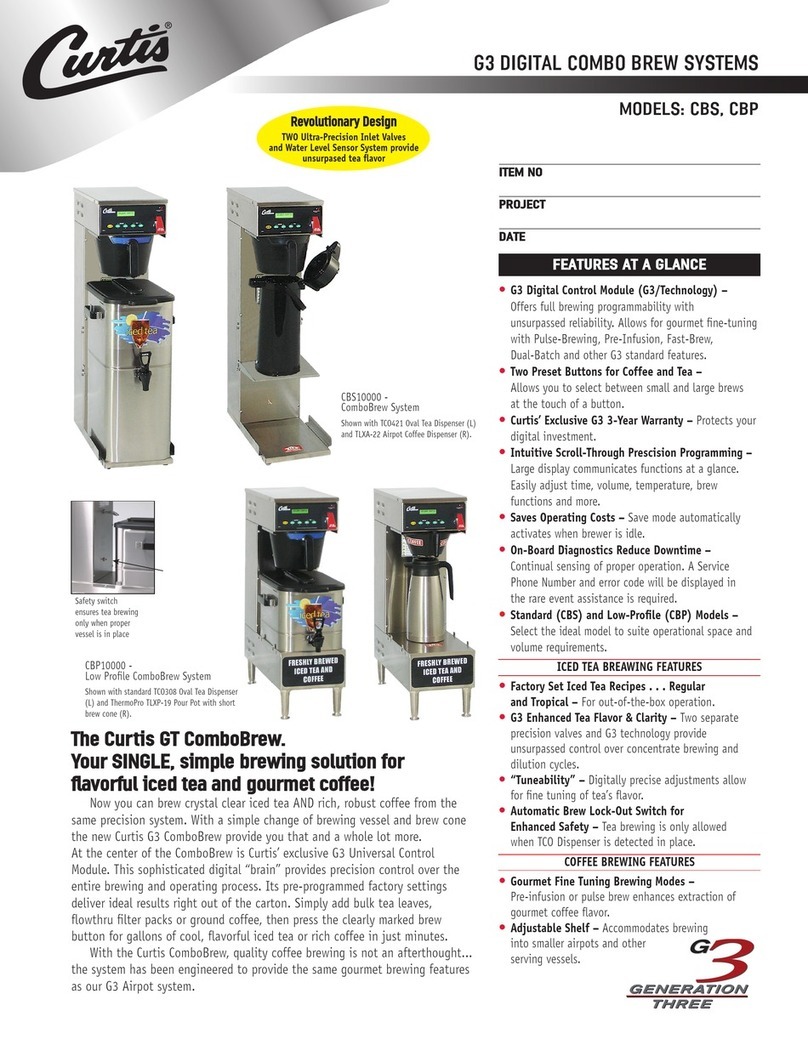
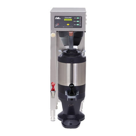
This Curtis Generation 4 System is factory pre-set and ready to go right from the box.
Following are the factory settings for your G4 Coffee Brewing System:
• Brew Temperature = 200°F • Water Bypass = On for LARGE & MEDIUM Brew Only
• Brew Volume = Set to Vessel Requirement.
System Requirements:
•WaterSource20–90psi(minimumowrateof1gpm)
• Electrical: See attached schematic for standard model or visit www.wilburcurtis.com for your model.
Model
G4GEMT
CAUTION: DO NOT
connect this brewer to hot
water. The inlet valve is
not rated for hot water.
CAUTION: Please use
this setup procedure
before attempting to use
this brewer. Failure to follow the
instructions can result in injury or the
voiding of the warranty.
IMPORTANT: Equipment
to be installed to comply
with applicable govern-
mental plumbing/electrical codes
having jurisdiction.
ISO9001:2008REGISTERED
WILBUR CURTIS CO., INC.
6913WestAccoStreet
Montebello,CA90640-5403
For the latest information go to
www.wilburcurtis.com
Tel:800-421-6150
Fax:323-837-2410
Forthelatestspecicationsandinformationgotowww.wilburcurtis.com
TechnicalSupport:1-800-995-0417M-F5:30 a.m.- 4:00 p.m.PT
Email: [email protected]
This equipment is designed for commercial use. Any servicing other than cleaning and routine maintenance
should be performed by an authorized Wilbur Curtis Company Service Technician.
• DO NOT immerse the unit in water or any other liquid
• Toreducetheriskofreorelectricshock,DONOTopenservicepanels.Therearenouserserviceable
parts inside.
• Keep hands and other items away from hot areas of the unit during operation.
• Never clean with scouring powders or harsh chemicals.
Important Safeguards/Symbols
Service Manual – G4 Gemini Twin Coffee Brewer
Wilbur Curtis Co., inC.
Symbols:
WARNINGS – To help avoid personal injury
Important Notes/Cautions – from the factory
Sanitation Requirements
NSF International requires the following water connection:
1. Aquickdisconnectoradditionalcoiledtubing(atleast2xthedepthoftheunit)isrequiredso
that the unit can be moved for cleaning.
2. Thisunitmustbeinstalledwithadequatebackowprotectiontocomplywithapplicablefederal,
state and local codes.
3.Waterpipeconnectionsandxturesdirectlyconnectedtoaportablewatersupplyshallbesized,
installed and maintained in accordance with federal, state, and local codes.
3. Connect the unit to electrical outlet with appropriate amperage rating (see serial tag on machine).
4.Oncepowerhasbeensuppliedtotheunit,ipthetoggleswitchtothe‘ON’position(locatedontherearof
theunit),thewatertankwillbegintoll.Whenthewaterlevelinthetankreachestheprobe,theheating
element(s) will turn on.
5. Water in the heating tank will require approximately a half hour before reaching operating temperature
(factorysettingof200°F).Whereapplicable,turnontheuniversalcontrolmodule(UCM).Whentheunit
reachesoperatingtemperature,itwilldisplay“READYTOBREW”.
NOTE:Awaterltrationsystemmustbeusedtohelpmaintaintrouble-freeoperation.Air must be
purged from the cartridge prior to connection to equipment.Inareaswithextremelyhardwater,
wehighlyrecommendtheuseofaCurtisapprovedwaterlter.Forourfulllineoflters,pleaselog
on to www.wilburcurtis.com.
SETUP STEPS
1.Theunitshouldbelevel(lefttoright-fronttoback),onasecuresurface.
2. Connectthewaterlinetothewaterinletttingontherearoftheunit.Watervolumeowtothemachine
shouldbeconsistent.Usetubingsizedsufcientlytoprovideaminimumowrateofonegallonperminute.
2
Your Curtis G4/Gold Cup Series is factory pre-set for optimum performance.
After connection to water and power; turn on the brewer at the rear toggle switch. You will hear a beep and the status lights will come on for a moment.
Thescreenwilldisplay .Next isdisplayed.Waterwillllthetank(2-3minutesdependingonwaterowrate).
Whentheproperlevelisreached willappearonthescreen.Ittakesapproximately30minutestoreachthesetpointtemperature.
Control will display when temperature reaches the set point. The unit is now ready to brew.
MODEL NUMBER
CONTROL BD NUMBER
READY TO BREW
HEATING
FILLING
1.BrewershouldbeON.Conrmthisatthetoggleswitchonthebackofthebrewer.ThetouchscreenshouldreadReadytoBrew.
2.Placeanclean,emptycoffeesatelliteonthewarmerdeck.
6. Startthebrewcyclebyholdyournger
on the desired brew icon. As soon as
youheartheclickofthebrewvalve,the
brew cycle has started and you can lift
yournger.
Brew Code: Youmayndthatwhenabrew
buttonispressed,akeypadappearsonthe
screen. This is a brew lock-out feature that
5. Transferthelledbrewbaskettothe
brewer.
3. Placeanewpaperlterintothebrew
basket.
4. Fill the brew basket with the proper
amount of ground coffee.
COFFEE BREWING INSTRUCTIONS
requires a code to be entered before a brew
will start. The default is OFF.
CAUTION: Whenenabled,assoonasyou
enter the brew code a brew cycle starts.
Refertopage8formoreinformationaboutthe
BrewCode.
Duringthebrewcycle,ananimated1½
gallon satellite server icon will appear on the
screen and a brew timer will count down the
time remaining on the brew cycle.
WARNING–AVOIDSCALDING:Removethebrewbasketcarefully.Thebrewbasketcontainshotcoffeegrounds.
The coffee vessel is heavy when full. Take precautions to avoid dropping when moving.

3
Touch Screen Control Module
The touch screen turns on when power is available to the controller. The screen will contain standard control features such as symbols and
buttons.Pressingtheseelementswithyourngertipwillactivatetheprogrammingfunctions.Thedefaultscreen,aswellassomeadded
control buttons are shown in the illustration below.
STATUS LIGHTS
BREW BUTTONS
CURTIS LOGO
TO ENTER PROGRAMMING
Tap Curtis logo 5 times to bring
up the ACCESS CODE screen.
RETURN TO HOME SCROLL RETURN TO PREVIOUS
UNDO
WARMERS
CONTROL SYMBOLS
All of these symbols may not be
visible at one time.
MAIN MENU screen contains six control icons:
RECIPES,CONTROLSETTINGS,BREWSETTINGS,
MODELSELECT,SETTINGSSUMMARYandEXIT.
ACCESS CODE screen. Default is 1 2 3 4.
Oncethecodeisentered,pressOK.The
main menu screen will appear.
The access code can be reset in Control
Settings,PASSWORDS.
PROGRAMMING
PROGRAMMING continued . . .

4
ThischartexplainshowtoentertheprogrammodeandmenuselectionsavailablefromtheMAINMENU.
Menu Tree
Tap “Curtis” logo 5 times
to enter Programming Mode
When installing new control board, default is Gemini Twin - Three Batch
Applies to Gemini models only
Applies to Gold Cup/Seraphim models only

5
Menu Features
b
Runs diagnostic tests
Display brew time
m
Displays various screen saver images
Displays banner name
Displays various icons (original or bag)
gallons, 1000 gallon increments,
gallons, 100 gallon increments, this
only.
only.
(resettable)
reset to restore factory defaults
US units or Metric units
Maintenance interval
Service telephone number
<MED> during brewing
<120 Min on GEMTIF/GEMSIF>
This applies to Gemini units only.
This applies to Gemini-IF units only.
This function is
This applies to Gemini and Gemini-IF units only.
No change
Auto test
models:
models:

6
Menu Features
5 Sec. - 15 Min.
10 Sec. On/10 Sec. Off
20 Sec. On/20 Sec. Off
30 Sec. On/30 Sec. Off
40 Sec. On/40 Sec. Off
50 Sec. On/50 Sec. Off
60 Sec. On/60 Sec. Off
Off, 10 Sec. - 15 Min.,
10 second increments
5 Min. - 25 Sec. 3 Min. - 32 Sec. 1 Min. - 52 Sec.
till end of brew cycle.
c
c
c
c
c
c
*
* Default settings

7
System Fault Messages
Maintenance required
Low water flow
Fill run error/overflow
Open sensor
Excess temperature
UPM-UCM communication
minutes on the intial tank fill or 120 seconds on
large brewers and 30 seconds on CGC brewer in
Break in the UPM-UCM communications circuit.
* This error is disabled in the CGC & Seraphim models.

8
Tap “Curtis” logo 5 times
to enter Programming Mode
The PASSWORDS screen will
Brew Access Code

9
There are two methods that can be used to change the default settings on G4 brewers. They can be programmed at the brewer by
thetouchscreenuniversalcontrolmodule(UCM)orthesettingscanbechangedusingtheUSB(universalserialbus)dataporton
thesideofthebrewer.UsingtheUSBconnectionandaashmemorydatastoragedevicewilleasilyreprogramthesettingssimply
by copying data.
TheashdrivecanuploadordownloadtheentiresettingfromoneG4brewer,intoanotherG4brewer.Thiseliminatestheneedto
walk through the usual steps in reprogramming that would be required when you use the touch screen to make a change. This is
an advantage for a service technician when standardizing the program settings on multiple G4 brewers.
UseaUSBdrivewithUSB2.0supportandatype-AUSBconnection.Storagecapacityshould
be2GBminimum.
IMPORTANT: Theashdrivemustbecompletelyblank.Beforestarting,pleaseeraseanyles
thatmaybeintheUSBdrive.
SOFTWARE INFORMATION TRANSFER
UPLOAD TO USB
1. Makesurethebrewerison.DeterminethattheG4breweryouwishtocopyisproperlyprogrammedforyourdesiredsettings.
2. ConnectanemptyashdriveintotheUSBportonthebrewer.TheUCMonthebrewerwilluploadalloftheparticularsetup
dataontotheashdrive.TheyellowLEDontopofthetouchscreenwilllightindicatingthatdataistransferring.Thiswillonly
take a second to complete.
DOWNLOAD TO BREWER
1. Select the brewer you wish to make the program changes on. The brewer should be on.
2. PlugtheloadedashdriveintotheUSBportonthebrewer.ThedatacopiedfromtherstG4brewerwillautomaticallydown-
load,overwritingallthesettingsthatwereonthesecondbrewer.
3. TheredLEDontheUCMwillindicatethatthedownloadisinprocess.Thiswillonlytakeasecond.
4. Oncethedownloadiscomplete,theUCMwillrebootinorderforthechangestotakeeffect.
5. Removetheashdrive.Thedownloadiscomplete.ThedataontheashdrivecanbedownloadedintoasmanyG4brewers
as needed.
USB – Easy Programming
ThisscreenwillbepresentedwhenevertheUSBashisinserted.
TheUCMwillalwayscreateabackupontheUSBashdrive
before downloading settings/recipes or screensaver.
Case 1
Settings/recipeslepresent,screensavernotpresent.User
hasselected‘DownloadfromUSB’forsettings/recipesle.
Case 2
Asabove,butuserhasselected‘UploadtoUSB’forsettings/
recipesle.Withthisaction,theoverwritewarningappears.
10
Illustrated Parts
Main View
1
2
3
4
5
6
7
8
9
10
16
17
18
19
11
12
13
14
15
24
25
26
27
28
29
30
31
20
21
22
23

11
ITEM NO. PART NO. DESCRIPTION
1 WC-5421 COVER,TOPSTAINLESSGEMTIF
2 WC-5527K* KIT,PROBEWATERLEVELO-RING&NUT
3 WC-37008 KIT,TANKLIDROUND
4 WC-43067* O-RING,4-1/2I.D.xØ.285C.S.SILICONE
5 WC-62033 TANKCOMPLETE,GEMTSWITHULTEMFITTINGS
6 WC-934-04* KIT,HEATINGELEMENT2.5KW220VW/JAMNUT&SILICONEWASHERS
7 WC-4382* GUARD,SHOCK-DOUBLEHEATINGELEMENTS
8 WC-522* THERMOSTAT,HILIMITHEATERDPST277V-40A
9 WC-43055 GUARD,SHOCKRESETTHERMOSTAT
10 WC-1438-101* SENSOR,TEMPERATURETANK
11 WC-29050* SPRAYHEADASSY,AFS-AMBER
12 WC-8559* RELAY,SOLIDSTATE40Aw/INTEGRATEDHEATSINK
13 WC-14045-101 CURRENTSENSORASSYG4
14 WC-39462 LABEL,BOTTOMPANELGEMTS
15 WC-1809 FAUCET,PS/HSPSERIESHOTWATER1/2-20UNF
16 GEM-6* FILTER,500PKGEM-12/230A
17 WC-3417 BREWCONE,ASSYW/SPLASHPOCKETBRWNSTYLIZEDGEMINHOTCOFFEE
18 WC-37310 KIT,BREWCONEALIGNMENTBRACKETSTAINLESS
19 WC-61393 COVER,FRONTW/AGEMTS
20 WC-5423 DECK,WARMERW/ASSYGEM12/312IL/612IL/12ILD/612ILD
21 WC-37102* KIT,WARMERELEMENT
21A WC-37163 KIT,WARMERELEMENT100W220VGENUSE
22 WC-3528 LEG,4”ADJUSTABLE3/8-16THRDSTYLIZED
23 GEM-3 SATELLITESERVER,1-1/2GAL.
24 WC-5310* TUBE,5/16IDx1/8WSILICONE
25 WC-5350* TUBE,SILICONEØ1/2”IDxØ3/4”ODx1/8”WALL
26 WC-2402P ELBOW,3/8NPTx3/8FLAREPLATED
27 WC-847* VALVE,INLET2GPM120V-10W
*RECOMMENDEDPARTSTOSTOCK
Illustrated Parts
Top Wrap
36
37
35
34
32
33
38
39
40

12
ITEM NO. PART NO. DESCRIPTION
27A WC-883 VALVE,INLET2GPM240V10W
28 WC-589-101 TRANSFORMER,120/230VAC-24VAC4.8VAw/LEADS&TERMINALS
28A WC-589-102 TRANSFORMER,240VAC-24V4.8VAW/LEADS&MOLEXCONNECTOR
29 WC-13450 HARNESSASSY,COMPLETETP2T10G4/GEMTS10G4/GEMTIF10G4
29A WC-13450-101 HARNESSASSYCOMPLETEG4TP2TG4TPC2T/G4GEMT/G4TP1T-30’S
30 WC-1501 FUSE,HOLDERASSYw/5AFUSE
31 WC-102* SWITCH,TOGGLESPST15A125VacRESISTIVE
31A WC-103 SWITCH,TOGGLENON-LITDPST25A125/250VACRESISTIVE
32 WC-37121 KIT,DUMPVALVELEFT
32A WC-853 VALVE,BREWDUMPLEFT240V12WGEM12D/TP/TPC
33 WC-442* SOLENOID,LOCKBREWCONERIGHT120VAC
33A WC-446 SOLENOID,LOCKBREWCONERIGHT220VTHERMOPRO/GEMTS
34 WC-2977-101K KIT,SPRAYHEADFITTING,GASKET&JAMNUT
35 WC-37122* KIT,DUMPVALVERIGHT
35A WC-854 VALVE,BREWDUMPRIGHT240V12WGEM12D/TP/TPC
36 WC-39812 LABEL,OUTERTOUCHSCREENGEMTSG4CURTISLOGO
37 WC-10000* CONTROLMODULE,TOUCHSCREENG4
38 WC-844-101* VALVE,BYPASS120V-14WNONADJUSTABLEWITHRESTRICTOR(WC-2945)
38A WC-844-102 VALVE,BY-PASS,220VNON-ADJUSTABLEW/RESTRICTOR(WC-2945)
39 WC-10001* UNIVERSALPOWERMODULE-G4
40 WC-10008 UNIVERSALHOSTADAPTER(USB)
Parts List
*RECOMMENDEDPARTSTOSTOCK
Rough-In Drawing

13
Electrical Schematic

14
Cleaning the Gemini
Regular cleaning and preventive maintenance is essential in keeping your coffee brewer looking and working like new.
To clean the coffee brewer and components, prepare a mild solution of dish washing detergent and warm water.
CAUTION – Do not use cleaning liquids, compounds or powders containing chlorine (bleach) or corrosives. These
products promote corrosion and will pit the stainless steel. USE OF THESE PRODUCTS WILL VOID THE WAR-
RANTY.
DAILY CLEANING
1. Wipe exterior surfaces with a damp cloth, removing spills and debris.
2. Slide the brew basket out and clean it. Wipe the spray head area with a cloth soaked in a mild detergent solution.
3. Rinse with a cloth soaked with clean water. Dry the brew basket and spray head area.
4. Drain drip trays of coffee. Water rinse.
5. Dry the tray.
WEEKLY CLEANING
1. Reach behind the brewer and turn off the power at the toggle switch. Allow the brewer to cool.
2. Clean the spray head and dome plate area.
a. Remove the spray head, unscrewing counterclockwise from the dome plate.
b. Thoroughly clean and rinse the dome plate area.
c. Clean the brew basket rails with a brush soaked with a mild detergent solution. Rinse the area with a cloth
soaked with clean water, removing any residual detergent.
d. Dry the area.
c. Attach the spray head.
Liquid Level Probe
Cleaning intervals for the probe are to be determined by the user or the service tech, based on water conditions. The
use of water lters, or the type of water lter that is being used can impact the service interval. Intervals can be from
one month to several years, however, replacing rather than cleaning the probe is preferable.
WARNING: Disconnect electrical power before removing access panels!
CAUTION: This procedure involves working with hot water and hot surfaces!
1. Unplug the power cord and shut off the water line.
2. Remove the top cover of the coffee brewer. Locate the heating tank and
remove the top cover.
3. Open the hot water faucet and drain the tank to a level about 3” below the tip of the probe.
4. Allow some time for the heating tank and liquid level probe to cool down before proceed-
ing.
5. Clean the tip of the probe using a Scotch-Brite™ scuff pad.
6. If a white residue is still visible on the probe, remove the probe and soak it in vinegar or a
scale removing chemical. Repeat this step until the probe is clean.
Cleaning the Satellite Server
To clean the satellite components, prepare a mild solution of detergent and warm water..
1. Remove lid from satellite. Clean the lid at the funnel area with a spiral brush and detergent solution.
2. Rinse the lid, removing all traces of cleaning solution.
3. Unscrew the handle/bonnet assembly and remove it from the dispensing faucet.
4. Pull the silicone seat cup from faucet stem and inspect it for wear, cracks, or hardening. Replace the seat cup
if necessary.

15
4
2
1
3
6
5
8
79
10
12
11
1
1A
2
3
4
5
6
7
7A
8
9
9A
10
11
12
WC-5622
WC-3307
WC-2102
WC-2005*
WC-2010C
WC-2025*
WC-2006*
WC-1800
WC-1841
WC-3705*
WC-1901A-103K
WC-1901A
WC-37102*
WC-3503*
WC-114R*
LID,SATELLITEPLASTICGEM3
LID,SATELLITESTAINLESS(OLDERUNITS)
GAUGEGLASSASSEMBLY8”
WASHER,SHIELDCAP1/8”
SHIELD,8INCHGAUGEGLASS
GAUGEGLASS,8INCH
WASHER,SHIELDBASE3/16”
FAUCET,S’NON-LOCKING
FAUCET,ESPBLACKNON-LOCKINGPLASTIC
KIT,FAUCETS’SERIES
KIT,SHANKASSY,FAUCETW/SHIELDBASEO-RING
SHANK,FAU.W/SHLD.BASE(UNITSBUILTAFTER2/15)
KIT,WARMERELEMENT100W120V (GEM-5 & -8)
LEG,SCREWBUMPER3/8”–16STD (GEM-5 & -8)
SWITCH,ROCKER(RED)120VSPST (GEM-5 & -8)
PART№ITEM№ DESCRIPTION
*Recommendedpartstostock.
Illustrated Parts List
GEM-3SATELLITESERVER,GEM-5,WARMER,
GEM-8WARMERSHORT
5. Clean all parts. Thoroughly rinse with clear warm water.
6. Dry and assemble the handle/bonnet parts. Hand-tighten the assembly onto the faucet.
7. Remove the gauge glass tube by unscrewing the gauge glass cap.
8. Clean the gauge glass tube and the two washers with a gauge brush and detergent solution. Rinse with clear
water. Dry the parts and assemble them onto the satellite.
DO NOT immerse the satellite in water or any other liquid.
9. Clean inside of the satellite. Remove coffee residue with the detergent solution.
10. Thoroughly rinse out the satellite with clear warm water.

ECN 16604 11/02/15 @ 10.0 rev F
Product Warranty Information
WilburCurtisCo.,Inc.certiesthatitsproductsarefreefromdefectsinmaterialandworkmanshipundernormaluse.Thefollowinglimitedwar-
ranties and conditions apply:
3 years,partsandlabor,fromoriginaldateofpurchaseondigitalcontrolboards.
2 years,parts,fromoriginaldateofpurchaseonallotherelectricalcomponents,ttingsandtubing.
1 year,labor,fromoriginaldateofpurchaseonallelectricalcomponents,ttingsandtubing.
Additionally,WilburCurtisCo.,Inc.warrantsitsgrindingburrsforforty(40)monthsfromdateofpurchaseor40,000poundsofcoffee,whichever
comesrst.Stainlesssteelcomponentsarewarrantedfortwo(2)yearsfromdateofpurchaseagainstleakingorpittingandreplacementpartsare
warranted for ninety (90) days from date of purchase or for the remainder of the limited warranty period of the equipment in which the component
is installed.
Allin-warrantyservicecallsmusthavepriorauthorization.Forauthorization,calltheTechnicalSupportDepartmentat1-800-995-0417.Effective
dateofthispolicyisApril1,2003.
Additional conditions may apply. Go to www.wilburcurtis.com to view the full product warranty information.
CONDITIONS&EXCEPTIONS
Thewarrantycoversoriginalequipmentattimeofpurchaseonly.WilburCurtisCo.,Inc.,assumesnoresponsibilityforsubstitutereplacementparts
installedonCurtisequipmentthathavenotbeenpurchasedfromWilburCurtisCo.,Inc.WilburCurtisCo.,Inc.willnotacceptanyresponsibility
if the following conditions are not met. The warranty does not cover and is void under the following circumstances:
1) Improper operation of equipment: The equipment must be used for its designed and intended purpose and function.
2) Improper installation of equipment: This equipment must be installed by a professional technician and must comply with all local electrical,
mechanical and plumbing codes.
3) Improper voltage: Equipment must be installed at the voltage stated on the serial plate supplied with this equipment.
4) Improper water supply: Thisincludes,butisnotlimitedto,excessiveorlowwaterpressureandinadequateoructuatingwaterowrate.
5) Adjustments and cleaning: Theresettingofsafetythermostatsandcircuitbreakers,programmingandtemperatureadjustmentsarethe
responsibility of the equipment owner. The owner is responsible for proper cleaning and regular maintenance of this equipment.
6) Damaged in transit: Equipment damaged in transit is the responsibility of the freight company and a claim should be made with the carrier.
7) Abuse or neglect (including failure to periodically clean or remove lime accumulations): Manufacturer is not responsible for variation
inequipmentoperationduetoexcessivelimeorlocalwaterconditions.Theequipmentmustbemaintainedaccordingtothemanufacturer’s
recommendations.
8) Replacement of items subject to normal use and wear: Thisshallinclude,butisnotlimitedto,lightbulbs,sheardisks,“0”rings,gaskets,
silicone tube, canister assemblies, whipper chambers and plates, mixing bowls, agitation assemblies and whipper propellers.
9) Repairs and/or Replacements aresubjecttoourdecisionthattheworkmanshiporpartswerefaultyandthedefectsshowedupundernormal
use.Alllaborshallbeperformedduringregularworkinghours.Overtimechargesaretheresponsibilityoftheowner.Chargesincurredby
delays,waitingtime,oroperatingrestrictionsthathindertheservicetechnician’sabilitytoperformserviceistheresponsibilityoftheownerof
theequipment.Thisincludesinstitutionalandcorrectionalfacilities.WilburCurtisCo.,Inc.willallowupto100miles,roundtrip,perin-warranty
service call.
RETURN MERCHANDISE AUTHORIZATION: All claims under this warranty must be submitted to the Wilbur Curtis Technical Support Depart-
mentpriortoperforminganyrepairworkorreturnofthisequipmenttothefactory.Allreturnedequipmentmustberepackagedproperlyinthe
originalcarton.Nounitswillbeacceptediftheyaredamagedintransitduetoimproperpackaging.NO UNITS OR PARTS WILL BE AC-
CEPTED WITHOUT A RETURN MERCHANDISE AUTHORIZATION (RMA). RMA NUMBER MUST BE MARKED ON THE CARTON OR
SHIPPING LABEL. All in-warranty service calls must be performed by an authorized service agent. Call the Wilbur Curtis Technical Support
Departmenttondanagentnearyou.
10/2015 F-3804 rev F
WILBUR CURTIS CO., INC.
6913 Acco St., Montebello, CA 90640-5403 USA | Phone: 800-421-6150 | Fax: 323-837-2410
Technical Support Phone: 800-995-0417 (M-F 5:30 a.m.- 4:00 p.m.PST)
Other manuals for G4GEMT
1
Table of contents
Other Curtis Coffee Maker manuals

Curtis
Curtis TLP12A User manual

Curtis
Curtis ALP3GT15A826 User manual

Curtis
Curtis ALP2GT12A000 User manual

Curtis
Curtis G4 Gemini Twin User manual

Curtis
Curtis PC-3GT User manual

Curtis
Curtis D60GT User manual

Curtis
Curtis PCGT3 User manual

Curtis
Curtis Gemini 12D Series User manual

Curtis
Curtis ALPHA 1X User manual

Curtis
Curtis G4GEMT User manual

Curtis
Curtis PC-4D User guide

Curtis
Curtis G4 CGC Series User manual

Curtis
Curtis ALP1GT Instruction Manual

Curtis
Curtis C1000AP User manual

Curtis
Curtis ALPHA 1GT User manual

Curtis
Curtis CBS User manual

Curtis
Curtis PCGT3 User manual

Curtis
Curtis D60GT10 User manual

Curtis
Curtis GEMTF User manual

Curtis
Curtis RU-150 User manual