Curtis Nitrogen Infusion Box User manual

Nitrogen
Infusion Box
USER GUIDE
READ AND SAVE THESE INSTRUCTIONS
NOTICE TO INSTALLER: Please leave this booklet with the machine.
øøøøø #
'$/*#'30/5$07&3 'SFW#
&RQÀJXUDWLRQYDULHV
0RGHO1,%VKRZQ

CONTENTS CL114
.H\)HDWXUHV6SHFLÀFDWLRQV6\VWHP5HTXLUHPHQWV............................................................................................FS104
,PSRUWDQW6DIHJXDUGV............................................................................................................................................. IS11
3UH,QVWDOODWLRQ&KHFNOLVW........................................................................................................................................PC1
,QVWDOODWLRQ,QVWUXFWLRQV............................................................................................................................................II43
&OHDQLQJ,QVWUXFWLRQV..............................................................................................................................................CI32
5RXJK,Q'UDZLQJ............................................................................................................................................... 5'
,OOXVWUDWHG3DUWV5HFRPPHQGHG3DUWV.................................................................................................................. IP190
7URXEOHVKRRWLQJ*XLGH ..........................................................................................................................................7*
3URGXFW:DUUDQW\....................................................................................................................................................3:
Contact Information
Wilbur Curtis Co., Inc.
6913 Acco Street | Montebello, CA 90640 US
Phone: 323-837-2300 | Toll Free: 800-421-6150
'PSUIFMBUFTUTQFDJmDBUJPOTBOEJOGPSNBUJPOHPUPXXXXJMCVSDVSUJTDPN
5PMM'SFF].POEBZ'SJEBZA.M.- 4:00 P.M.PT
Email: [email protected]
%VFUPDPOUJOVFEQSPEVDUJNQSPWFNFOUUIFQSPEVDUTJMMVTUSBUFEQIPUPHSBQIFEJOUIJTHVJEFNBZWBSZTMJHIUMZGSPNUIFBDUVBMQSPEVDU
/*#$0/5&/54-*45øø #

KEY FEATURES/SPECIFICATIONS/SYSTEM REQUIREMENTS FS104
Key Features
• Converts existing, N2pressurized, cold brew and drink systems for nitrogen infused cold drink dispensing.
• Gives cold drinks a creamy, velvety texture and taste. Can be used with cold brew coffee, beer, dairy drinks
and juices.
• Compact design allows for under-counter installation.
• Equipped with quick connect system for fast installation.
• BOEIFBEWFSTJPOTFOBCMFZPVUPTFSWFNPSFUIBOPOFUZQFBOEnBWPSPGOJUSPHFOJOGVTFEDPMEESJOLBUB
time (additional pouring heads required). You can also custom tailor the amount of nitrogen infusion for each
beverage individually.
6SHFLÀFDWLRQV6HOHFWHG0RGHOV
'LPHQVLRQV %HYHUDJH&RQQHFWLRQV N26XSSO\5HTXLUHPHQWV
02'(/ '(6&5,37,21 +(,*+7 :,'7+ '(37+ 6+,3
:(,*+7
6+,3
&8%(
%(9(5$*(
,1/(7
%(9(5$*(
287/(7 1&211(&725 135(6685(
1,% Nitrogen infusion
box, 1-head
4.61”
[12.1 cm]
6.43”
[16.3 cm]
10.02”
[25.5 cm]
5.0 lbs
[2.3 kg]
0.33 cu. ft.
[0.01 m3]3/8” John Guest 3/8” John Guest 3/8” John Guest
30 - 50 psi
207 - 345 kPa
1,% Nitrogen infusion
box, 2-head
4.61”
[12.1 cm]
6.43”
[16.3 cm]
10.02”
[25.5 cm]
5.0 lbs
[2.3 kg]
0.33 cu. ft.
[0.01 m3]
3/8” John Guest
X 2
3/8” John Guest
X 2 3/8” John Guest
30 - 50 psi
207 - 345 kPa
1,% Nitrogen infusion
box, 3-head
4.61”
[12.1 cm]
6.43”
[16.3 cm]
10.02”
[25.5 cm]
5.0 lbs
[2.3 kg]
0.33 cu. ft.
[0.01 m3]
3/8” John Guest
X 3
3/8” John Guest
X 3 3/8” John Guest
30 - 50 psi
207 - 345 kPa
* %HYHUDJHWHPSHUDWXUHQRWWRH[FHHG)&
** )RRGJUDGHQLWURJHQUHTXLUHG
3UHVVXUHLQWR1,%PXVWQRWH[FHHGSVLN3D
NIB, KEY FEATURES/SPECS/SYSTEM REQUIREMENTS 041219A

IMPORTANT SAFEGUARDS IS11
Symbols
This is the safety alert symbol. It is used to alert you to potential physical injury hazards. Obey all safety
messages that follow this symbol to avoid possible injury or death.
DANGER - Indicates a hazardous situation which, if not avoided, will result in death or serious injury.
WARNING - Indicates a hazardous situation which, if not avoided, could result in death or serious injury.
CAUTION - Indicates a hazardous situation which, if not avoided, could result in minor or moderate injury.
NOTICE - Indicates a situation which, if not avoided, could result in property damage.
IMPORTANT - Provides information and tips for proper operation.
SANITATION REQUIREMENTS
Important Safeguards/Conventions
WARNING:
• .BLFTVSFUIBUUIJTBQQMJBODFJTJOTUBMMFEBDDPSEJOHUPUIF*/45"--"5*0/*/4536$5*0/4CZRVBMJmFE
personnel before attempting to use it. Failure to follow the INSTALLATION INSTRUCTIONS could result
in personal injury or void the warranty.
• This appliance is designed for commercial use. Any service other than cleaning and preventive
maintenance should be performed by an authorized Wilbur Curtis service technician.
• This product is rated for dispensing beverage products at ambient or cold temperatures. Do not use it
to dispense hot beverage products. See SPECIFICATIONS section.
• DO NOT open the service panels. There are no user serviceable parts inside.
• Clean the appliance and any dispensers completelyCFGPSFVTJOHUIFNGPSUIFmSTUUJNFBTBDDPSEJOHUP
the CLEANING INSTRUCTIONS. Clean them regularly as instructed in the CLEANING INSTRUCTIONS.
• Use this appliance only for its intended use, brewing/dispensing cold beverages/water.
• This appliance is not intended for use by persons (including children) with reduced physical, sensory
or mental capabilities or lack of experience and knowledge, unless they have been given supervision
or instruction concerning use of the appliance by a person responsible for their safety. Children should
be supervised to ensure that they do not play with the appliance.
COLD BREW, IMPORTANT SAFEGUARDS/SYMBOLS 090619A
WARNING - This product can expose you to chemicals including Acrylamide and Bisphenol A (BPA),
which are known to the State of California to cause cancer and birth defects or other reproductive harm.
For more information visit www.P65Warnings.ca.gov.

IMPORTANT SAFEGUARDS IS11
COLD BREW, IMPORTANT SAFEGUARDS/SYMBOLS 090619A
CE Requirements
• This appliance must be installed in locations where it can be overseen by trained personnel.
• For proper operation, this appliance must be installed where the temperature is between 5°C to 35°C.
• This appliance is not suitable for outdoor use.
• This appliance must not be cleaned by water jet.
• This appliance can be used by persons aged from 18 years and above if they have been given supervision or
instruction concerning use of the appliance in a safe way and if they understand the hazards involved.
• Keep the appliance out of reach of children aged less than 18 years.
• Appliances can be used by persons 18 years and above with reduced physical, sensory or mental capabilities
or lack of experience and knowledge if they have been given supervision or instruction concerning use of the
appliance in a safe way and understand the hazards involved.
• Children under the age of 18 years should be supervised to ensure they do not play with the appliance.
• Cleaning and user maintenance shall not be made by children unless they are older than 18 years and
supervised.
• This appliance is intended to be used in household and similar applications such as:
oTUBGGLJUDIFOBSFBTJOTIPQTPGmDFTBOEPUIFSXPSLJOHFOWJSPONFOUT
oCZDMJFOUTJOIPUFMTNPUFMTBOEPUIFSSFTJEFOUJBMUZQFFOWJSPONFOUT
– bed and breakfast type environments.
• This appliance not intended to be used in applications such as:
– farm houses
• Access to the service areas permitted by Authorized Service personnel only.
• The A-Weighted sound pressure level is below 70 dBA.

Checklist
The checklist below will assist you in preparing your location for the installation of your equipment. Please make
sure that everything is prepared to these requirements prior to scheduling your installation. See the ILLUSTRATED
PART S section for a list of available installation accessories.
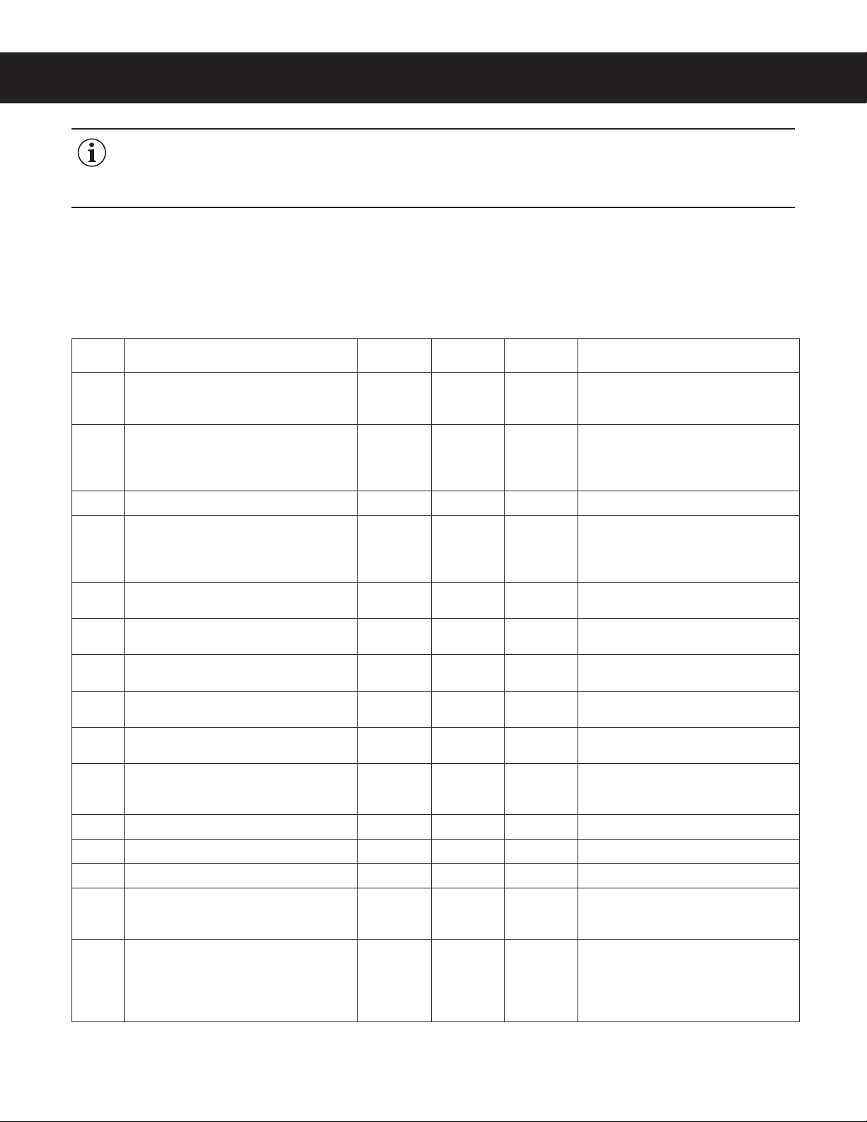
REQUIRED SYSTEM COMPONENTS
DESCRIPTION NIB1
QTY/TYPE
NIB2
QTY/TYPE
NIB3
QTY/TYPE COMMENTS
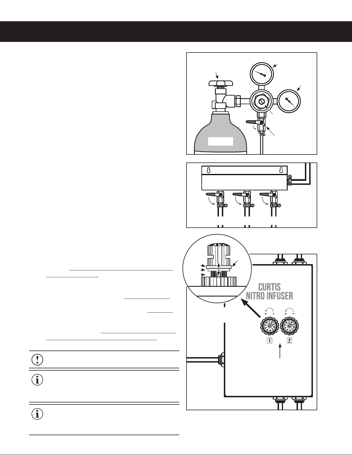
A food grade nitrogen (N2) supply with a
nitrogen regulator set to 30 - 50 psi
(207 - 345 kPa)
111
A kegerator or under counter refrigerator
with approximately 4.75”(H) x 6.42”(W) x
10.02”(D) of free space on one of the sides,
inside, for installation of the NIB
111
Allow room for plastic beverage and
N2 lines (allow for bend angles) and
mounting bracket (if used) around
mounting location.
Product keg(s)* 1 2 3 Sanke or Cornelius (Corny)
Keg connector(s) 1 Sanke or
2 Corny
2 Sanke or
4 Corny
3 Sanke or
6 Corny
Sanke kegs require 1 D style coupler per
keg. Corny kegs require 1 liquid ball lock
connector and 1 gas ball lock connector
per keg.
Dedicated tap(s) with a nitro stout faucet
installed 123
Tees or manifold for N2 supply lines. One
supply line required for NIB and each keg.**
1 tee or
1:2 manifold
2 tees or
1:3 manifold
3 tees or
1:4 manifold
A manifold allows for greater system
control (independent shut off of keg N2).
3/8” beverage line (food grade) - - From nitrogen regulator to gas
distribution tees or manifold
3/8” beverage line (food grade) 1 x 3 feet
minimum
1 x 3 feet
minimum
1 x 3 feet
minimum
From gas distribution tees or manifold
to NIB
3/8” beverage line (food grade) 1 x 3 feet
minimum
2 x 3 feet
minimum
3 x 3 feet
minimum
From gas distribution tees or manifold to
kegs
1/4” beverage line (food grade)* 1 x 3 feet
minimum
2 x 3 feet
minimum
3 x 3 feet
minimum
From taps to inside of kegerator with
a minimum of 3’ of line running from
kegerator ceiling
John Guest 3/8” barb(s) 1 2 3
John Guest 1/4” barbs 2 4 6
Hose Clamps 7 14 21 Oetiker type recommended
0HVKÀOWHUVWUDLQHUIRRGJUDGH 123
Optional, recommended. Installed on
each beverage supply line between keg
and NIB.
3/8” John Guest type plug - - -
Unused input(s) and output(s) on NIB
should be plugged when not in use. This
allows for the purchase of larger capacity
NIB than needed to allow for future
expansion.
*7KH1,%WKHNHJVEHYHUDJHVXSSO\OLQHVDQGÀOWHUVLIDSSOLFDEOHPXVWEHLQVWDOOHGLQVLGHWKHNHJHUDWRUUHIULJHUDWRU
The kegerator/refrigerator must be set between 36°F/2°C to 40°F/4°C to avoid spoilage.
** Add additional tees/manifold ports for any standard cold brew kegs/faucets attached to the system that do not utilize ports on the NIB.
PRE-INSTALLATION CHECKLIST PC1
NIB, PRE-INSTALLATION CHECKLIST 041119A
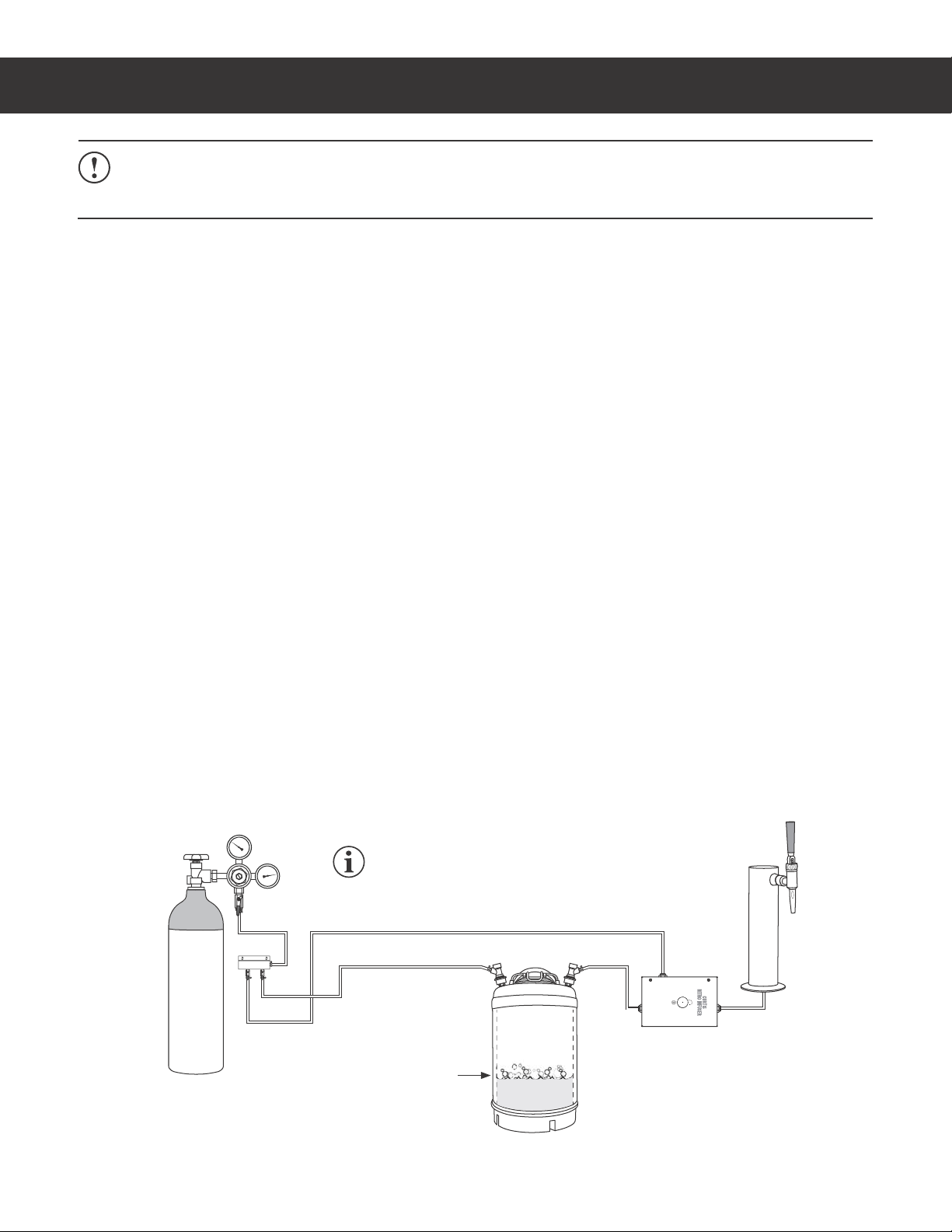
IMPORTANT: The Curtis Nitrogen Infusion Box is designed for locations with an existing draft system. If
the NIB will be a component of a new draft system installation, please consult with your draft technician for
integration of the NIB into your new draft system. See the INSTALLATION INSTRUCTIONS section for a
typical system layout.

INSTALLATION INSTRUCTIONS II43
/*#*/45"--"5*0/*/4536$5*0/4ø 090919F
WARNING:*OTUBMMBUJPOJTUPCFQFSGPSNFEPOMZCZBRVBMJmFEJOTUBMMFS
WARNING: Do not exceed the maximum gas pressure and beverage temperature stated in the
SPECIFICATIONSTFDUJPO
IMPORTANT:0CTFSWFBMMHPWFSOJOHDPEFTBOEPSEJOBODFT
IMPORTANT: Before proceeding with installation, make sure that you have all the required components
listed in the PRE-INSTALLATION CHECKLIST
Example of Possible System Layout
&RQÀJXUDWLRQYDULHVEDVHGRQUHTXLUHPHQWV
7ZRQLWUREHYHUDJHOLQHV1,%DQGRQHVWDQGDUGFROGEUHZOLQHVKRZQ
Food grade nitrogen
(N2) supply with
regulator
Quick N2
VKXWRႇYDOYH
NIB and
keg N2
VKXWRႇ
YDOYHV
Manifold a
IN
IN
IN
OUT
OUT
OUT
Chilled
product keg
(Sanke b)
Chilled
product keg
(Corny b)
Chilled
product keg
(Corny b)
Filter/strainer
(optional)
5HIULJHUDWHGHQYLURQPHQW
Standard
cold brew
faucet
Nitro stout
faucets
Nitrogen
infusion box
(NIB)
IN
N2 IN
OUT
Main N2 gas
VKXWRႇYDOYH
a
(LWKHUDPDQLIROGRUDVHULHVRIWHHVPD\EHXVHGWRFUHDWHWKHQHFHVVDU\QXPEHURI1OLQHVIRUWKHV\VWHP
b
(LWKHUW\SHRINHJPD\EHXVHGE\VXEVWLWXWLQJWKHFRUUHFWW\SHRIÀWWLQJV

Installation
Mount the NIB
1 Determine the location for the NIB, inside the
LFHFSBUPSPSSFGSJHFSBUPS5IF/*#DBOCFJOTUBMMFE
IPSJ[POUBMMZPSWFSUJDBMMZ
2 If using the mounting bracket, loosen the appropriate
screws on the back of the NIB and slide the mounting
QMBUFJOUPQMBDFUIFOSFUJHIUFOUIFTDSFXT6TFUIF
included self-drilling screws to attach the NIB to the
TFMFDUFEMPDBUJPO
3 If using the double-sided tape to mount the NIB, clean
the desired mounting location thoroughly with rubbing
BMDPIPMCFGPSFNPVOUJOHUPBTTVSFHPPEBEIFTJPO
Allow the alcohol to dry, then remove the backing
from the double sided tape on the back of the NIB
NPVOUJOHQMBUFBOEBGmYJUUPUIFTFMFDUFEMPDBUJPO
Connect the N2and Beverage Delivery Lines
4 Insert the plastic tubing coming from the N2supply
into the N2*/DPOOFDUPSPOUIF/*#1VTIUIFUVCJOHJO
VOUJMJUTUPQT
5 Insert the plastic tubing coming from the keg into the
#&7&3"(&*/DPOOFDUPSPOUIF/*#1VTIUIFUVCJOH
JOVOUJMJUTUPQT3FQFBUGPSTZTUFNTIBWJOHNPSFUIBO
POFCFWFSBHFMJOF
6 Insert the plastic tubing running to the faucet into
UIF#&7&3"(&065DPOOFDUPSPOUIF/*#1VTIUIF
UVCJOHJOVOUJMJUTUPQT3FQFBUGPSTZTUFNTIBWJOH
NPSFUIBOPOFCFWFSBHFMJOF
7 1MVHBOZVOVTFE#&7*/BOE#&7065DPOOFDUPST
8 Secure all John Guest connectors using locking clips
$VSUJT1/8$OPUJODMVEFE1VMMCBDLHFOUMZ
on each of the tubes inserted into the NIB, in turn, to
NBLFTVSFUIBUUIFZBSFQSPQFSMZTFDVSFE
DPOUJOVFE
INSTALLATION INSTRUCTIONS II43
/*#*/45"--"5*0/*/4536$5*0/4ø 090919F
IMPORTANT: 8IFONPVOUJOHUIFOJUSPHFO
infusion box (NIB), be sure to allow room for the
plastic beverage and N2lines (allow for bend
BOHMFTBSPVOEUIFNPVOUJOHMPDBUJPO
&RQ¿JXUDWLRQYDULHV
NIB2 shown
)URP12
supply
)URP
product
kegs
N2 IN
N2 IN
Clip, install on N2 IN
and all BEV. IN and
BEV. OUT connectors
BEV.
IN
BEV.
IN
BEV.
OUT
BEV.
OUT
To
faucets

Prepare for Operation
9 Open the main gas shut-off valve and adjust the
regulator on the N2supply to between 30 - 50
QTJL1BQTJL1BSFDPNNFOEFE
The pressure required for your system may vary,
CVUEPOPUFYDFFEQTJ
10 0QFOUIFRVJDLTIVUPGGWBMWFPOUIFUBOL0QFOUIF
keg and NIB N2supply valves on the manifold, if
BQQMJDBCMF
11 Clear air from the line(s) by opening the faucet(s)
VOUJMBMMMBSHFBJSCVCCMFTBSFSFNPWFE
12 Sanitize the dispensing system according to the
instructions in the CLEANING INSTRUCTIONS
TFDUJPOCFGPSFVTJOHUIFTZTUFNGPSUIFmSTUUJNF
8IJMFnVTIJOHPVUUIFTZTUFNDIFDLUIFCFWFSBHF
EFMJWFSZMJOFDPOOFDUJPOTGPSMFBLT
13 1MBDFUIFQSPEVDULFHTJOTJEFUIFLFHFSBUPS
(set between 36°F/2°C and 40°F/4°C) and allow
TVGmDJFOUUJNFGPSUIFQSPEVDUJOUIFLFHUPDIJMM
14 Connect the chilled beverage product keg(s) to the
TZTUFN$POOFDUUIFLFH/2supply line (IN) and
LFHCFWFSBHFMJOF065
15 Remove the covers over the level adjustment
LOPCTMake sure that each knob's red collar is
VOMPDLFEBTTIPXO4FUUIFMFWFMTUPQPTJUJPO
16 If the dispensed beverage does not have enough
foam, turn the knob(s) slightly counter-clockwise
*GUIFGPBNMFWFMJTUPPIJHIPSUIFGBVDFUJT
"blowing foam", turn the knob(s) sightly clockwise
3FUFTUBOEBEKVTUVOUJMUIFGPBNMFWFMJT
BDDFQUBCMF-PDLUIFLOPCTBOESFQMBDFUIFLOPC
DPWFSTXIFOEPOFDo not push the red collar all
the way down when locking (see diagram)!
INSTALLATION INSTRUCTIONS II43
/*#*/45"--"5*0/*/4536$5*0/4ø 090919F
NIB infusion
OHYHODGMXVWPHQW
knobs
NOTE: 1VSHFP[NMPGQSPEVDUBU
UIFCFHJOOJOHPGFBDICVTJOFTTEBZ$VSUJT
recommends that the N2gas supply be turned
PGGBUOJHIUXIFOOPUJOVTF
NOTICE: To avoid damage to the adjustment
WBMWFEPOPUPWFSUJHIUFOUIFLOPC
NOTE: 5IFBEKVTUNFOULOPCJTTFOTJUJWF4NBMM
BEKVTUNFOUTSFTVMUJOTJHOJmDBOUDIBOHF5IFSFJT
a short delay before infusion adjustments take
FGGFDUBUUIFGBVDFU
8QORFNWKHNQREVDQGWXUQWKHPFRXQWHUFORFNZLVHIRU
PRUHKHDGDQGFORFNZLVHIRUOHVVKHDG
Manifold
Keg 2 N2
Keg 1 N2
N2 IN
NIB N2
ON ON ON &RQ¿JXUDWLRQ
YDULHV
4XLFNVKXWRႇ
YDOYH
ON
Main gas
VKXWRႇYDOYH
Pressure
DGMXVWPHQW
5HPDLQLQJ
gas in tank
Gas
pressure
N2 tank
Adjustment Knob
Side View
Lock
Wrong
Unlock
Red
collar

NOTICE - Do not use cleaning liquids, compounds or powders containing chlorine (bleach) or corrosives.
5IFTFQSPEVDUTQSPNPUFDPSSPTJPOBOEXJMMEBNBHFUIFmOJTIFT USE OF THESE PRODUCTS WILL VOID
THE WARRANTY. Do not immerse the unit in water or any other liquid.
CLEANING INSTRUCTIONS CI32
NIB, CLEANING INSTRUCTIONS 101818A
Cleaning and Sanitizing - Daily
Overview
The following 2 step process involves the use of an
empty keg (one for each beverage line). Each keg
JTmMMFEXJUIDMFBOFSTBOJUJ[FS5IFMJRVJEJTESBXO
UISPVHIUIFFOUJSFTZTUFNUPDMFBOBOETBOJUJ[FJU
1) Clean
a Use a commercial, food grade, cold brew
system cleaner. Mix it according to the directions
on the package.* Fill an empty keg with enough
DMFBOFSUPmMMBMMCFWFSBHFMJOFTCFUXFFOUIFLFH
and the faucet. Fill additional kegs with cleaner
for each beverage line in the system.
b Connect the N2 and beverage output lines from
the system to the keg(s).
c Place an empty container under the faucet(s).
d Open each faucet, pouring until you see
DMFBOJOHnVJECFHJOUPmMMUIFDPOUBJOFS
e Allow the system to sit for the amount of time
TQFDJmFECZUIFDMFBOFSNBOVGBDUVSFSXJUI
UIFDMFBOJOHTPMVUJPOJOUIFIPTFTMJOFTCFGPSF
nVTIJOH
Product keg
emptied and
¿OOHGZLWK
FOHDQLQJ
sanitizing
VROXWLRQ
(see 2 step
process, above)
Nitrogen
infusion box (NIB)
f Empty the remaining cleaning solution from the
keg(s). Fill the keg(s) with rinse water. Open the
GBVDFUT3FmMMUIFLFHTXJUIXBUFSVOUJMBMMUIF
DMFBOJOHTPMVUJPOIBTCFFOnVTIFEGSPNUIFTZTUFN
g Discard the solution that poured into the container.
2) Sanitize
h Use a commercial, food grade, cold brew system
TBOJUJ[FS.JYJUBDDPSEJOHUPUIFEJSFDUJPOTPOUIF
package.* Fill an empty keg with enough solution
UPmMMBMMCFWFSBHFMJOFTCFUXFFOUIFLFHBOEUIF
faucet. Fill additional kegs with cleaner for each
beverage line in the system.
i Connect the N2 and beverage output lines from the
system to the keg(s).
j Place an empty container under the faucet(s).
k 0QFOFBDIGBVDFUQPVSJOHVOUJMZPVTFFTBOJUJ[JOH
TPMVUJPOCFHJOUPmMMUIFDPOUBJOFS
l At a minimum, allow the system to sit for the
BNPVOUPGUJNFTQFDJmFECZUIFTBOJUJ[JOHTPMVUJPO
manufacturer. Curtis recommends leaving the
TBOJUJ[FSJOUIFTZTUFNXIFOOPUJOVTF'MVTIUIF
system thoroughly with water before returning it to
use.
IMPORTANT:6LQJOHEHYHUDJHOLQHV\VWHPVKRZQ
2QV\VWHPVZLWKPRUHWKDQEHYHUDJHOLQHDOO
EHYHUDJHOLQHVPXVWEHFOHDQHGVDQLWL]HG
Cleaning/Sanitizing Process Setup
Food grade nitrogen
1VXSSO\
'2127XVHKRWZDWHU6ROXWLRQWHPSHUDWXUHVKRXOGEHEHWZHHQDPELHQWDQG)&

ROUGH-IN DRAWINGS RD103
NIB, ROUGH-IN DRAWING 101918A
NIB1
NIB2
1.75 in
[4.4 cm]
1.75 in
[4.4 cm]
3.06 in
[7.8 cm]
3.06 in
[7.8 cm]
4.56 in
[11.6 cm]
4.75 in
[12.1 cm]
4.56 in
[11.6 cm]
4.75 in
[12.1 cm]
2.56 in
[6.5 cm]
2.56 in
[6.5 cm]
11.92 in
[30.3 cm]
11.92in
[30.3 cm]
1.30 in
[3.3 cm]
2.18 in
[5.5 cm]
0.88 in
[2.2 cm]
1.56 in
[4.0 cm]
1.35 in
[3.4 cm]
4.91 in
[12.5 cm]
4.91 in
[12.5 cm]
1.00 in
[2.5 cm]
1.00 in
[2.5 cm]
10.02 in
[25.4 cm]
10.02 in
[25.4 cm]
6.43 in
[16.3 cm]
8.33 in
[21.1 cm]
6.42 in
[16.3 cm]
8.32 in
[21.1 cm]

ROUGH-IN DRAWINGS RD103
NIB, ROUGH-IN DRAWING 101918A
NIB3
1.75 in
[4.4 cm]
3.06 in
[7.8 cm]
4.56 in
[11.6 cm]
4.75 in
[12.1 cm]
2.56 in
[6.5 cm]
11.92 in
[30.3 cm]
1.30 in
[3.3 cm]
1.30 in
[3.3 cm]
0.88 in
[2.2 cm]
1.56 in
[4.0 cm]
1.35 in
[3.4 cm]
1.35 in
[3.4 cm]
4.91 in
[12.5 cm]
1.00 in
[2.5 cm]
10.02 in
[25.4 cm]
6.42 in
[16.3 cm]
8.32 in
[21.1 cm]

ILLUSTRATED PARTS/RECOMMENDED PARTS IP190
NIB, ILLUSTRATED PARTS/RECOMMENDED PARTS 120618A
1
2
4
11
12
6
7
8
9
NIB - Installation Accessories - Exploded View
3
10
5
ITEM # PART # DESCRIPTION USE
1 WC-53170K KIT, INSTALLATION NIB TO CONVERT 3/8 INCH O.D. BEVERAGE IN AND OUT
CONNECTIONS FOR USE WITH 1/4 INCH O.D. TUBING
2 WC-65096K KIT, PLATE MOUNTING
TO MOUNT NIB TO WALL. MAY BE MOUNTED 2 WAYS
USING 2 SELF DRILLING SCREWS OR DOUBLE SIDED TAPE
(BOTH INCLUDED)
3 WC-2564 PLUG, STEM 3/8 TUBE JOHN GUEST TO PLUG UNUSED BEVERAGE IN AND OUT CONNECTIONS
4 WC-53118-120K KIT, TUBING 3/8 OD X 10FT LONG
SYSTEM BEVERAGE LINE CONNECTIONS. CONNECTS
DIRECTLY TO BEVERAGE IN AND OUT JOHN GUEST
CONNECTORS.
5 WC-4621 SCREW, 10-16 X3/4 HEX HD SELF DRILLING 18-8 SS REPLACEMENT MOUNTING PLATE SCREWS
6 WC-2431 CLIP, LOCKING 3/8” TUBE JOHN GUEST SECURING TUBING IN JOHN GUEST CONNECTOR
7 WC-53170 TUBING, 3/8” O.D. X 1/4” I.D. CLEAR PVC USE ITEM 4
8 WC-14023 CLAMP, TUBING 8.8-10.5MM SS OETIKER CLAMPING 3/8 O.D. TUBING
9 WC-29133 FITTING, BARB 1/4 X 3/16 CONNECTS 1/4 INCH I.D. TUBING TO 3/16 INCH I.D. TUBING
10 WC-3545 CAP, PUSH-ON WC-29125 NIB COVERS THE INFUSION LEVEL KNOB(S)
11 WC-37582 KIT, SALES DEMO/INSTALLATION FOR CORNY KEGS TEMPORARY INSTALLATION KITS (WITHOUT MANIFOLD)
FOR DEMONSTRATION PURPOSES
12 WC-37583 KIT, SALES DEMO/INSTALLATION FOR SANKE KEGS
Parts List
3.00 in
[7.62 cm]

Troubleshooting Guidelines
5IJTUSPVCMFTIPPUJOHHVJEFJEFOUJmFTTPNFCVUOPUBMMPGUIFQPTTJCMFDBVTFTGPSQSPCMFNTUIBUDBOPDDVS
Nothing Comes Out of the Faucet or Flow Out of the Faucet is Slow
1 $IFDLUPTFFJGUIFOJUSPHFOTVQQMZUBOLJTFNQUZPSMPX
2 $IFDLUPNBLFTVSFUIBUUIFSFHVMBUPSJTTFUUPCFUXFFOQTJL1B
$IFDLUPNBLFTVSFUIBUUIFNBJOUBOLWBMWFUIFRVJDLTIVUPGGWBMWFBOEUIFNBOJGPMEWBMWFTBSFDPNQMFUFMZ
PQFO
4PNFLFHTBSFFRVJQQFEXJUIBTIVUPGGWBMWF*GZPVSLFHJTFRVJQQFEXJUIBTIVUPGGWBMWFNBLFTVSFUIBUJUJT
DPNQMFUFMZPQFO
.BLFTVSFUIBUUIFMJEPOUIFLFHJTUJHIUMZTIVUBOEUIBUJUJTOPUMFBLJOH
6 $IFDLGPSBMFBLZPSDSJNQFE/2TVQQMZMJOFCFUXFFOUIFTVQQMZUBOLBOEUIFLFHT$IFDLUPNBLFTVSFBMM
/TVQQMZDPOOFDUJPOTBSFUJHIU$IFDLGPSMFBLZLFHmUUJOHT
$IFDLGPSBDMPHHFECFWFSBHFTVQQMZMJOFmMUFS
8 $IFDLGPSBDMPHHFECFWFSBHFTVQQMZMJOF"DPNNPODBVTFJTBLFHUIBUJTCFJOHTUPSFECFMPXGSFF[JOH
3BJTFUIFLFHTUPSBHFUFNQFSBUVSFUPCFUXFFO¡'¡'¡$¡$UPQSFWFOUUIFCFWFSBHFMJOFTGSPN
GSFF[JOH
Product Flows, But There is Too Little or No Foam
1 $IFDLUPNBLFTVSFUIBUUIF/*#/2WBMWFPOUIFNBOJGPMEJTPQFO
2 $IFDLGPSBMFBLZPSDSJNQFE/2TVQQMZMJOFCFUXFFOUIFTVQQMZUBOLBOE/*#
$IFDLUPTFFJGUIFOJUSPHFOTVQQMZUBOLJTMPX
$IFDLUPNBLFTVSFUIBUUIFSFHVMBUPSJTTFUUPCFUXFFOQTJ
L1B
.BLFTVSFUIBUBMMBJSCVCCMFTBSFQVSHFEGSPNUIFTZTUFN
6 $IFDLGPSBNBMGVODUJPOJOHGBVDFU$IFDLGPSDMPHHFEPSNJTTJOHDPNQPOFOUT
$IFDLUPNBLFTVSFUIBUUIFOP[[MFSFTUSJDUPSQMBUFIPMFTBSFDMFBS
$IFDLUPNBLFTVSFUIBUUIF/*#BEKVTUNFOULOPCJTQSPQFSMZTFU5VSODPVOUFS
DMPDLXJTFTMJHIUMZUPJODSFBTFJOGVTJPOBOEUFTU/PUFUIBUUIFSFXJMMCFBTMJHIU
EFMBZCFGPSFUIFBEKVTUNFOUUBLFTFGGFDUBUUIFGBVDFU3FQFBUBTOFDFTTBSZ
Too Much Foam
1 $IFDLUPTFFJGUIFLFHJTFNQUZ
2 $IFDLGPSBNBMGVODUJPOJOHGBVDFU$IFDLGPSDMPHHFEPSNJTTJOHGBVDFUDPNQPOFOUT
.BLFTVSFUIBUUIF/*#BEKVTUNFOULOPCJTQSPQFSMZTFU5VSODMPDLXJTFTMJHIUMZUPEFDSFBTFJOGVTJPOBOEUFTU
/PUFUIBUUIFSFXJMMCFBTMJHIUEFMBZCFGPSFUIFBEKVTUNFOUUBLFTFGGFDUBUUIFGBVDFU3FQFBUBTOFDFTTBSZ
Only Gas and Spurts of Liquid Come Out of Faucet
1 $IFDLUPTFFJGUIFLFHJTFNQUZ
2 $IFDLUPNBLFTVSFUIBUUIF/*#BEKVTUNFOULOPCJTQSPQFSMZBEKVTUFE
4PNFLFHTBSFFRVJQQFEXJUIBTIVUPGGWBMWF*GZPVSLFHJTFRVJQQFEXJUIBTIVUPGGWBMWFNBLFTVSFUIBUJUJT
DPNQMFUFMZPQFO
.BLFTVSFUIBUUIFMJEPOUIFLFHJTUJHIUMZTIVUBOEUIBUJUJTOPUMFBLJOH
$IFDLUPNBLFTVSFUIBUUIFSFBSFOPLJOLTPSDMPHTJOUIFCFWFSBHFMJOFCFUXFFOUIFLFHBOEUIF/*#
6 $IFDLGPSBNBMGVODUJPOJOHGBVDFU$IFDLGPSDMPHHFEPSNJTTJOHGBVDFUDPNQPOFOUT
TROUBLESHOOTING GUIDE TG43
/*#5306#-&4)005*/((6*%& ø $
NIB infusion
level knobs

TROUBLESHOOTING GUIDE TG43
/*#5306#-&4)005*/((6*%& ø $
Watery Output from Faucet
$IFDLUIFLFHUFNQFSBUVSF,FFQUIFLFHUFNQFSBUVSFBU¡'¡$PSMFTT"GUFSUIFLFHUFNQFSBUVSFJTMPXFSFE
TMPTIUIFDPOUFOUTBSPVOEUPSFNJY
Product Taste Has Deteriorated or Has Become Slimy
1 $IFDLUIFQSPEVDUFYQJSBUJPOEBUFPOUIFLFH3FQMBDFPMEQSPEVDU
2 5IFQSPEVDUNBZIBWFTQPJMFECFDBVTFUIFLFHUFNQFSBUVSFIBTCFFOBCPWF¡'¡$3FQMBDFTQPJMFE
QSPEVDUBOENBJOUBJOBLFHTUPSBHFUFNQFSBUVSFCFUXFFO¡'¡'¡$¡$
5IFDPPMJOHMJOFTJOUIFGBVDFUUPXFSBSFOPUXPSLJOH*OTQFDUBOESFQBJSBTOFDFTTBSZ
5IFCFWFSBHFMJOFTIBWFOPUCFFODMFBOFEBTTQFDJmFE4FFCleaning Instructions
Product Tastes of Soap or Chemicals
.BLFTVSFUIFCFWFSBHFMJOFTBSFUIPSPVHIMZnVTIFEXJUIXBUFSGPMMPXJOHDMFBOJOH
Adjustment Knob Does Not Turn
.BLFTVSFBEKVTUNFOULOPCJTOPUMPDLFE
Adjustment Knob Has No Effect - Foam Level Does Not Change When Knob is Turned
.BLFTVSFUIBULOPCMPDLSFEDPMMBSIBTOPUCFFOQVTIFEBMMUIFXBZEPXO,OPCEPFTOPUFOHBHFXJUIWBMWF
TIBGUXIFODPMMBSJTJOUIFXSPOHQPTJUJPO
Adjustment Knob - Side View
Locking collar in
unlocked position
Locking collar in
locked position
Locking collar in wrong position Locking collar in locked position Locking collar in unlocked position
.QREWXUQVEXWKDVQRHႇHFWRQIRDPOHYHO Knob does not turn .QREWXUQVDQGDGMXVWVIRDPOHYHO
Wrong
position
Locked
position
Unlocked
position

TROUBLESHOOTING GUIDE TG43
/*#5306#-&4)005*/((6*%& ø $
Schematic - NIB1
BEVERAGE IN
N2 IN
BEVERAGE OUT
ITEM # DESCRIPTION
A ORIFICE
B NEEDLE VALVE
CELBOW
D CHECK VALVE
E INJECTOR VALVE
A
B
C
C
D
E
ADJUSTMENT
KNOB

TROUBLESHOOTING GUIDE TG43
/*#5306#-&4)005*/((6*%& ø $
Schematic - NIB2
BEVERAGE IN (1)
BEVERAGE IN (2)
BEVERAGE OUT (1)
BEVERAGE OUT (2)
N2 IN
ITEM # DESCRIPTION
A ORIFICE
B NEEDLE VALVE
CELBOW
D CHECK VALVE
E INJECTOR VALVE
F Y BARB
A
ADJUSTMENT
KNOB 1
ADJUSTMENT
KNOB 2
A
B
B
F
C
C
C
C
D
D
E
E

TROUBLESHOOTING GUIDE TG43
/*#5306#-&4)005*/((6*%& ø $
Schematic - NIB3
N2 IN
ITEM # DESCRIPTION
A ORIFICE
B NEEDLE VALVE
CELBOW
D CHECK VALVE
E INJECTOR VALVE
F Y BARB
A
A
A
B
B
B
F
F
C
C
C
C
C
C
D
D
D
E
E
E
BEVERAGE IN (1)
BEVERAGE IN (2)
BEVERAGE IN (3)
BEVERAGE OUT (1)
BEVERAGE OUT (2)
BEVERAGE OUT (3)
ADJUSTMENT
KNOB 1
ADJUSTMENT
KNOB 2
ADJUSTMENT
KNOB 3

PRODUCT WARRANTY PW3
:LOEXU&XUWLV&R,QFFHUWL¿HVWKDWLWVSURGXFWVDUHIUHHIURPGHIHFWVLQPDWHULDODQGZRUNPDQVKLSXQGHUQRUPDOXVH7KHIROORZLQJOLPLWHG
ZDUUDQWLHVDQGFRQGLWLRQVDSSO\
1year, from original date of purchase.
CONDITIONS & EXCEPTIONS
7KHZDUUDQW\FRYHUVRULJLQDOHTXLSPHQWDWWLPHRISXUFKDVHRQO\7KHZDUUDQW\GRHVQRWFRYHU
• Adjustments and cleaning: Valve and regulator adjustments are the responsibility of the equipment owner. The owner is responsible for
proper cleaning and regular maintenance of this equipment.
• Replacement of equipment due to normal use and wear: This shall include, but is not limited to, “O” rings, gaskets, silicone tubing,
silicone elbows.
• Losses due to down time: Curtis is not responsible for any losses due to down time caused by the equipment requiring repair or replacement.
7KHZDUUDQW\LVYRLGXQGHUWKHIROORZLQJFLUFXPVWDQFHV
• Improper operation of equipment: The equipment must be used for its designed and intended purpose and function.
• Improper installation of equipment: This equipment must be installed by a professional technician and must comply with all local
electrical, mechanical and plumbing codes.
• Improper gas supply: 7KLVLQFOXGHVEXWLVQRWOLPLWHGWRH[FHVVLYHRUORZJDVSUHVVXUHDQGLQDGHTXDWHRUÀXFWXDWLQJJDVÀRZUDWH
• Damaged in transit: Equipment damaged in transit is the responsibility of the freight company and a claim should be made with the carrier.
• Abuse or neglect (including failure to periodically clean or remove lime accumulations): The manufacturer is not responsible for
variation in equipment operation due to excessive lime or local water conditions. The equipment must be maintained according to the
manufacturer’s recommendations.
• 8QDXWKRUL]HGUHSDLURUPRGLÀFDWLRQThis equipment must be returned to the factory for repair or replacement. Opening the service
panel will void the warranty.
• 0RGLÀHG0LVVLQJ6HULDO7DJThe serial number label (tag) must not be defaced or removed.
Repair or replacement LVVXEMHFWWR&XUWLV¶GHFLVLRQWKDWWKHZRUNPDQVKLSRUSDUWVZHUHIDXOW\DQGWKHGHIHFWVVKRZHGXSXQGHUQRUPDOXVH
Return Merchandise Authorization (RMA):$OOFODLPVXQGHUWKLVZDUUDQW\PXVWEHVXEPLWWHGWRWKH:LOEXU&XUWLV7HFKQLFDO6XSSRUW'HSDUWPHQW
SULRUWRUHWXUQRIWKLVHTXLSPHQWWRWKHIDFWRU\All returned equipment must be properly re-packaged in the original carton and received by
Curtis within 45 days following the issuance of a RMA.1RXQLWVZLOOEHDFFHSWHGLIWKH\DUHGDPDJHGLQWUDQVLWGXHWRLPSURSHUSDFNDJLQJ
NO UNITS WILL BE ACCEPTED WITHOUT A RETURN MERCHANDISE AUTHORIZATION (RMA). THE RMA NUMBER MUST BE MARKED
ON THE CARTON OR SHIPPING LABEL.
130%6$58"33"/5::1ø "
This manual suits for next models
4
Table of contents