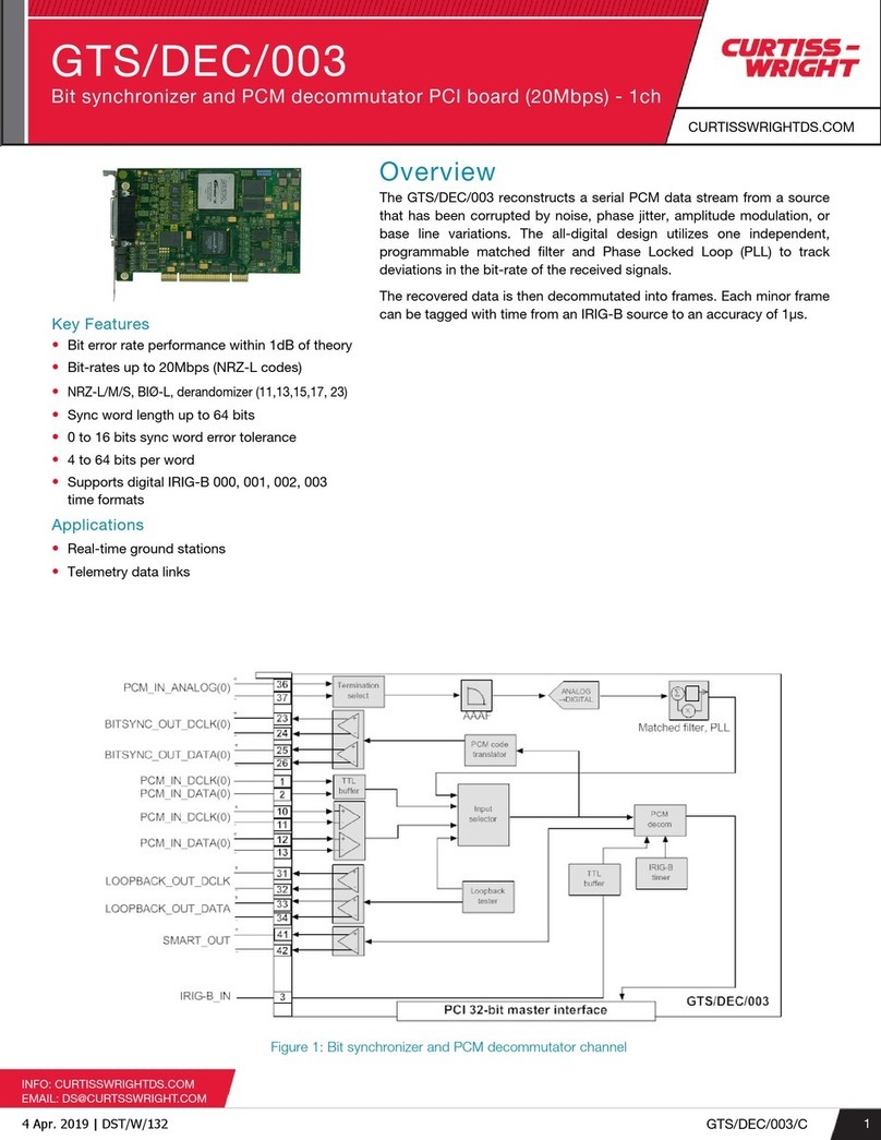
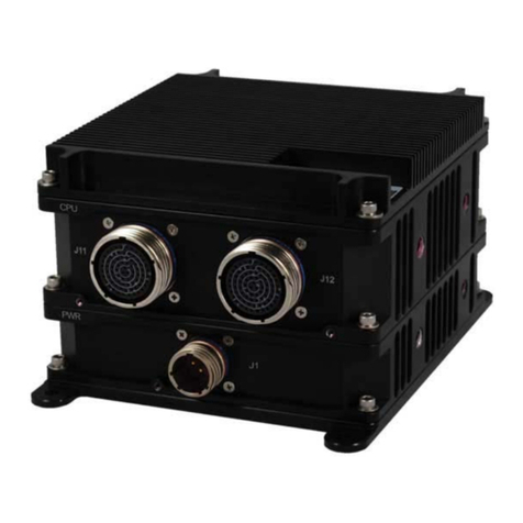
Curtiss-Wright GT200 VME Application guide

GT200
VME
Hardware Reference
Document No. G-T-MR-G1VME6U#-A-0-A2


FOREWORD
The information in this document has been carefully checked and is believed to be accurate; however, no
responsibility is assumed for inaccuracies. Curtiss-Wright Controls, Inc. reserves the right to make
changes without notice.
Curtiss-Wright Controls, Inc. makes no warranty of any kind with regard to this printed material
including, but not limited to, the implied warranties of merchantability and fitness for a particular
purpose.
Copyright 2005 Curtiss-Wright Controls, Inc. All Rights Reserved.
GT200is a registered trademark of Curtiss-Wright Controls, Inc.
HyperTerminal®is a registered trademark of Microsoft Corporation.
Patents pending for network status messaging and host interrupt queue functions.
LinkXchangeis a registered trademark of Curtiss-Wright Controls, Inc.
Motorola/FreeScale®is a registered trademark of the Motorola Corporation.
Tsi148™ is a trademark of Tundra Semiconductor Corporation.
Any reference made within this document to equipment from other vendors does not constitute an
endorsement of their product(s).
Revised:September 28,2005
Curtiss-Wright Controls, Inc. Embedded Computing
Data Communication
2600 Paramount Place Suite 200
Fairborn, OH 45324USA
Tel: (800) 252-5601 (U.S. only)
Tel: (937) 252-05601

FCC
This product is intended for use in industrial, laboratory, or military environments. This product uses and
emits electromagnetic radiation, which may interfere with other radio and communication devices. The
user may be in violation of FCC regulations if this device is used in other than the intended market
environments.
CE
As a component part of another system, this product has no intrinsic function and is therefore not subject
to the European Union CE EMC directive 89/336/EEC.

TABLE OF CONTENTS
1. Introduction................................................................................................................................................ 1-1
1.1 How to Use This Manual.......................................................................................................... 1-1
1.1.1 Purpose .................................................................................................................. 1-1
1.1.2 Scope .....................................................................................................................1-1
1.2 Related Information.................................................................................................................. 1-1
1.3 Quality Assurance .................................................................................................................... 1-2
1.4 Technical Support..................................................................................................................... 1-3
1.5 Ordering Process ...................................................................................................................... 1-3
2. PRODUCT OVERVIEW........................................................................................................................... 2-1
2.1 Overview .................................................................................................................................. 2-1
2.1.1 Features..................................................................................................................2-1
2.2 SFP Media Options................................................................................................................... 2-2
2.2.1 LED Descriptions .................................................................................................. 2-3
2.3 Topologies................................................................................................................................ 2-4
2.3.1 Non-Redundant Ring ............................................................................................. 2-4
2.3.2 Redundant Ring ..................................................................................................... 2-4
2.3.3 Point-to-Point......................................................................................................... 2-5
2.3.4 Daisy Chain ........................................................................................................... 2-5
2.3.5 Monitoring............................................................................................................. 2-5
2.3.6 LinkXchange GLX4000 Physical Layer Switch.................................................... 2-6
2.3.7 VLX2500 Physical LayerSwitch ........................................................................... 2-7
2.3.8 Switch Ring ........................................................................................................... 2-8
2.3.9 Redundant Switch Ring ......................................................................................... 2-9
3. INSTALLATION....................................................................................................................................... 3-1
3.1 Overview .................................................................................................................................. 3-1
3.2 Unpack the Card....................................................................................................................... 3-1
3.3 Inspect the Card........................................................................................................................ 3-1
3.4 Configure the GT200 VME Card ............................................................................................. 3-2
3.4.1 Configuration Switch (S2) ..................................................................................... 3-2
3.5 Configure the GT200 PMC Card.............................................................................................. 3-3
3.5.1 Installing SFP Modules.......................................................................................... 3-3
3.6 Install the Cards........................................................................................................................ 3-3
3.7 Connect the Fiber Optic Cables................................................................................................ 3-4
3.8 Troubleshooting........................................................................................................................ 3-5
4. OPERATION ............................................................................................................................................. 4-1
4.1 Overview .................................................................................................................................. 4-1
4.2 Functional Description ............................................................................................................. 4-1
4.2.1 Network Paradigm................................................................................................. 4-1
4.2.2 Ring Topology....................................................................................................... 4-2
4.2.3 Physical Interface................................................................................................... 4-2
4.2.4 Network Size ......................................................................................................... 4-2
4.2.5 Interface Standards ................................................................................................ 4-3
4.2.6 Network Framing................................................................................................... 4-3
4.2.7 Link Interface ........................................................................................................ 4-3
4.2.8 Network Throughput ............................................................................................. 4-3
4.2.9 Error Detection ...................................................................................................... 4-3
4.2.10 Latency ................................................................................................................ 4-4
4.2.11 Message Ordering................................................................................................ 4-4
4.2.12 Memory ............................................................................................................... 4-4
4.2.13 FIFO Buffers........................................................................................................ 4-4
4.2.13.1 Retransmit FIFO ............................................................................... 4-4
4.2.13.2 Receive FIFO.................................................................................... 4-4
4.2.14 Network Status Messaging .................................................................................. 4-5
4.2.14.1 Shared Information ........................................................................... 4-5
4.2.15 Modes of Operation ............................................................................................. 4-5
4.2.15.1 Write-Me-Last Mode ........................................................................ 4-5
4.2.15.2 TX Enable......................................................................................... 4-6
Copyright 2005 i GT200 VME Hardware Reference

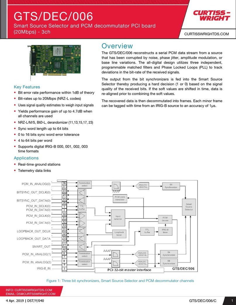
TABLE OF CONTENTS
4.2.15.3 RX Enable......................................................................................... 4-6
4.2.15.4 RT Enable ......................................................................................... 4-6
4.3 GT200 Block PMC Diagram.................................................................................................... 4-7
4.3.1 Network Logic....................................................................................................... 4-7
4.3.2 Host Logic ............................................................................................................. 4-7
4.4 User Interfaces.......................................................................................................................... 4-8
4.4.1 VME Interface ....................................................................................................... 4-8
4.4.1.1 VME Slave.......................................................................................... 4-8
4.4.1.2 VME System Controller...................................................................... 4-8
4.4.1.3 VME CR/CSR..................................................................................... 4-8
4.4.2 RS-232 Interface.................................................................................................... 4-8
4.4.3 10/100 Ethernet Interface....................................................................................... 4-9
4.4.4 10/100/1000 Ethernet Interface.............................................................................. 4-9
4.4.5 GT200 VME Configuration................................................................................... 4-9
4.4.5.1 Configuring GT200 VME Via RS-232 (Serial) Console .................... 4-9
4.4.5.2 Configuring GT200 VME Via Ethernet............................................ 4-10
4.4.5.3 Factory Default Configuration .......................................................... 4-10
4.4.5.4 VME Address Window Configuration.............................................. 4-10
4.4.5.5 VME Slot Number Configuration..................................................... 4-11
4.4.6 GT Network Interface Configuration................................................................... 4-11
4.4.6.1 Ethernet Interface Configuration....................................................... 4-12
APPENDICES
Appendix A - Specifications ......................................................................................................................... A-1
Appendix B – Ordering Information ............................................................................................................. B-1
GLOSSARY................................................................................................................................ GLOSSARY-1
INDEX .................................................................................................................................................INDEX-1
FIGURES
Figure 2-1 GT200 VME Card ........................................................................................................................ 2-1
Figure 2-2 SFP Transceiver Module .............................................................................................................. 2-2
Figure 2-3 GT200 VME Card Faceplate ........................................................................................................ 2-3
Figure 2-4 Switch Ring .................................................................................................................................. 2-8
Figure 2-5 Redundant Switch Ring ................................................................................................................ 2-9
Figure 3-1 Fiber-optic Simplex LC Connector............................................................................................... 3-4
Figure 3-2 Fiber-optic Duplex LC Connector ................................................................................................ 3-4
Figure 4-1 GT200 VME Block Diagram........................................................................................................ 4-1
Figure 4-2 Replicated Shared Memory .......................................................................................................... 4-2
Figure 4-3 Configuration Switch Diagram..................................................................................................... 4-6
Figure 4-4 GT200 PMC Block Diagram ........................................................................................................ 4-7
Copyright 2005 ii GT200 VME Hardware Reference

TABLE OF CONTENTS
TABLES
Table 3-1 Slot Configuration Switches .......................................................................................................... 3-2
Table 3-2 System Control Switches ............................................................................................................... 3-2
Copyright 2005 iii GT200 VME Hardware Reference


1. INTRODUCTION
1.1 How to Use This Manual
1.1.1 Purpose
This document is a reference manual for the GT200 VME card. It provides a physical and
functional description of the GT200 VME card. The manual describes how to unpack, set
up, install, and operate the hardware.
1.1.2 Scope
This information is intended for systems designers, engineers, and network installation
personnel. You need at least a systems level understanding of general computer
processing, computer networking, and hardware operation to effectively use this manual.
Style Conventions
• Called functions are italicized. For example, OpenConnect().
• Data types are italicized. For example, int.
• Function parameters are bolded. For example, Action.
• Path names are italicized. For example, utility/sw/cfg.
• File names are bolded. For example, config.c.
• Path file names are italicized and bolded. For example, utility/sw/cfg/config.c.
• Hexadecimal values are written with a “0x” prefix. For example, 0x7e.
• For signals on hardware products, an ‘Active Low’ is represented by prefixing
the signal name with a slash (/). For example, /SYNC.
• Code and monitor screen displays of input and output are boxed and indented on
a separate line. Text that represents user input is bolded. Text that the computer
displays on the screen is not bolded. For example:
C:\ls
file1 file2 file3
• Large samples of code are Courier font, at least one size less than context, and
are usually on a separate page or in an appendix.
1.2 Related Information
• American National Standard for VME64 (ANSI/VITA 1-1994(R2002)),
VITA www.vita.com.
• American National Standard for VME64 Extensions (ANSI/VITA 1.1 –
1998(R2003)), VITA
• American National Standard for 2eSST (ANSI/VITA 1.5 – 2003), VITA
P. O. Box 19658 Fountain Hills, AZ 85269 USA
• PCI Local Bus Specification, Revision 2.2, 18 DEC 1998, PCI SIG
Copyright 2005 1-1 GT200 VME Hardware Reference

INTRODUCTION
• CMC Specification (IEEE P1386/Draft 2.4a), Revision 21 MAR 2001,
IEEE
• PMC Specification (IEEE P1386.1/Draft 2.4a), Revision 21 JAN 2001,
IEEE
• LinkXchange GLX4000 Physical Layer Switch User Reference Manual
(Doc. No. F-T-MR-L5XL144), Curtiss-Wright Controls, Inc.
• LinkXchange VLX2500 Physical Layer Switch User Reference Manual
(Doc. No. F-T-MR-VLX2500#), Curtiss-Wright Controls, Inc.
• GT200 Hardware Reference for PCI and PMC Cards, Curtiss-Wright
Controls, Inc. (Document No. G-T-MR-G1PCPMCP-A-0-xx)
• GT200 API Guide, Curtiss-Wright Controls, Inc.
(Document No. G-T-ML-G1AP1)
• Curtiss-Wright Controls, Inc web address: www.cwcembedded.com
1.3 Quality Assurance
Curtiss-Wright Controls’ Corporate policy is to provide our customers with the highest
quality products and services. In addition to the physical product, the company provides
documentation, sales and marketing support, hardware and software technical support,
and timely product delivery. Our quality commitment begins with product concept, and
continues after receipt of the purchased product.
Curtiss-Wright Controls’ Quality System conforms to the ISO 9001 international standard
for quality systems. ISO 9001 is the model for quality assurance in design, development,
production, installation, and servicing. The ISO 9001 standard addresses all 20 clauses of
the ISO quality system, and is the most comprehensive of the conformance standards.
Our Quality System addresses the following basic objectives:
• Achieve, maintain, and continually improve the quality of our products
through established design, test, and production procedures.
• Improve the quality of our operations to meet the needs of our customers,
suppliers, and other stakeholders.
• Provide our employees with the tools and overall work environment to fulfill,
maintain, and improve product and service quality.
• Ensure our customer and other stakeholders that only the highest quality
product or service will be delivered.
The British Standards Institution (BSI), the world’s largest and most respected
standardization authority, assessed Curtiss-Wright Controls’ Quality System. BSI’s
Quality Assurance division certified we meet or exceed all applicable international
standards, and issued Certificate of Registration, number FM 31468, on May 16, 1995.
The scope of Curtiss-Wright Controls’ registration is: “Design, manufacture and service
of high technology hardware and software computer communications products.” The
registration is maintained under BSI QA’s bi-annual quality audit program.
Customer feedback is integral to our quality and reliability program. We encourage
customers to contact us with questions, suggestions, or comments regarding any of our
products or services. We guarantee professional and quick responses to your questions,
comments, or problems.
Copyright 2005 1-2 GT200 VME Hardware Reference

INTRODUCTION
1.4 Technical Support
Technical documentation is provided with all of our products. This documentation
describes the technology, its performance characteristics, and includes some typical
applications. It also includes comprehensive support information, designed to answer any
technical questions that might arise concerning the use of this product. We also publish
and distribute technical briefs and application notes that cover a wide assortment of
topics. Although we try to tailor the applications to real scenarios, not all possible
circumstances are covered.
Although we have attempted to make this document comprehensive, you may have
specific problems or issues this document does not satisfactorily cover. Our goal is to
offer a combination of products and services that provide complete, easy-to-use solutions
for your application.
If you have any technical or non-technical questions or comments, contact us. Hours of
operation are from 8:00 a.m. to 5:00 p.m. Eastern Standard/Daylight Time.
• Phone: (937) 252-5601 or (800) 252-5601
• E-mail: [email protected]
• Fax: (937) 252-1465
• World Wide Web address: www.cwcembedded.com
1.5 Ordering Process
To learn more about Curtiss-Wright Controls’ products or to place an order, please use
the following contact information. Hours of operation are from 8:00 a.m. to 5:00 p.m.
Eastern Standard/Daylight Time.
• Phone: (937) 252-5601 or (800) 252-5601
• E-mail: [email protected]
• World Wide Web address: www.cwcembedded.com
Copyright 2005 1-3 GT200 VME Hardware Reference

INTRODUCTION
This page intentionally left blank
Copyright 2005 1-4 GT200 VME Hardware Reference

2. PRODUCT OVERVIEW
2.1 Overview
Curtiss-Wright Controls GT200 VME card is a single-slot, single-card computer that
utilizes a Motorola MPC8540 I/O processor, Tundra Tsi148 VME to PCI/X Bridge, 256
MB of DDR SDRAM and 128 MB of Flash memory. The GT200 VME card has one
PMC slot in which a GT200 PMC card is installed.
S1
Reset
S2
OPEN
1
2
3
4
5
6
7
8
9
10
Figure 2-1 GT200 VME Card
2.1.1 Features
The GT200 VME has the following features:
• Supports concurrent network and host accesses with no loss of network data or
need to implement network flow control
• Status LEDs that report link status
• Two Small Form Factor Pluggable (SFP) media options available— short
wavelength laser (850 nm) and long wavelength laser (1300 nm)
• 2.5 Gbps fiber-optic interface with redundant transceiver option for network
topology redundancy
• Operates with the LinkXchange family of switches (2.5 Gbps or faster)
• Tundra Tsi148TM PCI/X-to-VME Bridge
• Supports VME legacy protocols
Copyright 2005 2-1 GT200 VME Hardware Reference

PRODUCT OVERVIEW
• Two independent single channel DMA controllers
• Supports 2eSST and 2eVME protocols
• RS-232 serial port
• Two Ethernet interfaces, one 10/100/1000BaseTX and one 10/100BaseTX
• VME64x form factor, will operate in VME64 3-row backplane
2.2 SFP Media Options
The physical media interface of the GT200 design uses SFP transceiver modules. These
modules are hot swappable, providing an efficient way to modify the media interface
configuration as needed.
Two basic SFP media options are available for the GT200. These media options are a
long wavelength laser (1300 nm) and short wavelength laser (850 nm). All cards use a
Duplex LC style connector available from most major cable manufacturers.
Figure 2-2 SFP Transceiver Module
Long wavelength laser interconnections are recommended for distances longer than 250
meters, as loss in multimode fiber degrades connections with short wavelength lasers past
this distance.
The short wavelength version is useful for intrasystem connections, where you are
connecting between cards on the same backplane. It is also suited for short reach
intersystem connections (< 250 m).
The SFP transceivers comply with the Small Form-factor Pluggable transceiver
MultiSource Agreement (SFP MSA) to ensure compatibility between the different
transceiver manufacturers.
Copyright 2005 2-2 GT200 VME Hardware Reference

PRODUCT OVERVIEW
2.2.1 LED Descriptions
Six pairs of status LEDs along with RJ-45 connector LEDs are visible from the front
panel of the GT200 VME card. The front panel LEDs are shown in Figure 2-3.
From the left end of the panel:
Power ON LED (Green) – Enabled when power is applied to the card
Card Fail LED (Red) – Turns off when board has successfully booted
Ethernet 10/100/1000
• Connector – Tx activity LED (Green) & Rx activity LED (Green)
• 100 Mbps speed indicator LED (Green)
• 1Gbps speed indicator LED (Green)
Ethernet 10/100
• Connector – Tx activity LED (Yellow) & Rx activity LED (Green)
• 10 Mbps speed indicator LED (Green)
• 100 Mbps speed indicator LED (Green)
Fiber Communication Status LEDs
• The Link Select LED (LS) indicates which channel of the GT200 board is
selected. When the LED is off, channel 0 is selected. When the LED is on,
channel 1 is selected.
• The Link Up LED (LU) turns on when the selected channel is receiving a valid
GT200 signal.
• The Signal Detect LEDs (R0, R1) indicate a signal is being received by the
corresponding transceiver.
• The Laser Enable LEDs (T0, T1) indicate the corresponding transceiver is turned
on.
Figure 2-3 GT200 VME Card Faceplate
Copyright 2005 2-3 GT200 VME Hardware Reference

PRODUCT OVERVIEW
2.3 Topologies
There are various topologies for the GT200 VME card. These topologies should cover
most customer applications, though if another topology is desired contact Curtiss-Wright
Controls, Inc. Technical Support to see if it is possible. The topologies are:
Non-redundant ring
Redundant ring
Point-to-Point
Daisy Chain
Monitoring
Switch ring
Redundant switch ring
2.3.1 Non-Redundant Ring
This is the simplest of the topologies, with a single transmit/receive connection per node.
Any data written to one node is broadcast to all nodes. A break in one node of fiber
caused the ring to be broken. This topology would be used in a system where a failure in
the ring is not critical.
255
…
3
2
1
0
2.3.2 Redundant Ring
This topology is the same as a non-redundant ring; only a second ring is added using the
second transceiver to create a ring with data flowing in the opposite direction. A failure
in one of the rings does not prevent data from flowing to all the nodes. This topology
would be used in critical systems where a break in the ring cannot be tolerated.
1
Tx1
Tx0 Rx1
Rx0Tx1
Tx0 Rx1
Rx0
7
5
4
3
2 6
Copyright 2005 2-4 GT200 VME Hardware Reference

PRODUCT OVERVIEW
2.3.3 Point-to-Point
This is a special version of the non-redundant ring where there are just two nodes.
1
6
2.3.4 Daisy Chain
This topology only allows data to flow in one direction. This topology is used where data
does not need to be sent back to the sending node. The first node in the chain could be a
remote sensor sending data to several receiving nodes.
2 53
1
2.3.5 Monitoring
A monitoring topology is a non-redundant ring with one of the nodes transmitting the
data on its second transceiver to a monitoring node. The monitoring node can be used to
watch the status of the ring and check the ring’s health.
M
5
4
3
2
6
1
Copyright 2005 2-5 GT200 VME Hardware Reference

PRODUCT OVERVIEW
2.3.6 LinkXchange GLX4000 Physical Layer Switch
The GLX4000 Physical Layer Switch has the following features:
• Up to 144 non-blocking I/O ports.
• Up to 4.25 Gbps/port data rate.
• 48 Small Form Factor, Pluggable (SFP) transceiver modules per SFP port card.
• 48 (SFP) transceiver modules per SFP Retimed port card
• 48 IEEE 1394b "Firewire" copper media ports per IEEE 1394b port card.
• Port cards and pluggable transceivers may be mixed in one system.
• Supports Loop, Point-to-Point, One-to-Many communication links.
• Supports multiple physical media options including short wavelength (850 nm), long
wavelength (1300 nm), and HSSDC2.
• Automatic port fault isolation.
• Front panel indicators:
• Signal Detect.
• Transmitter ON.
• Heartbeat.
• Flash Write.
• Fan/Temperature Alarm.
• Watchdog.
• Out-of-band control through an Ethernet port.
• Can be controlled from a remote location.
• Dual-redundant hot-swappable power supplies.
• Hot-swappable fans.
• Hot-pluggable Small Form-factor transceiver modules.
• Hot-pluggable port cards.
• Multiple temperature monitoring points within the enclosure.
• Configuration data stored on a removable CompactFlash card.
• Automatic fan speed control based on enclosure temperature.
• Fan tachometer monitor.
For detailed information regarding the GLX4000 features and operation, contact
Curtiss-Wright Controls, Inc. and request a copy of the GLX4000 Physical Layer Switch
Hardware Reference Manual or visit our web site.
Copyright 2005 2-6 GT200 VME Hardware Reference

PRODUCT OVERVIEW
2.3.7 VLX2500 Physical LayerSwitch
Curtiss-Wright Controls’ VLX2500 Physical LayerSwitch
provides the following features:
• 16 non-blocking SFP transceiver ports (with optional 8-port
expansion card)
• 3.2 Gbps/port baud rate
• 25.6 Gbps total bandwidth (51.2 Gbps with optional 8-port
expansion card)
• Supports Arbitrated Loop, Point-to-Point, One-to-Many
communication links
• Optional bypass of retiming circuitry for each port
• Retimed ports support short wavelength (850 nm), long
wavelength (1300 nm), and HSSDC2 physical media options
• SFP transceiver MultiSource Agreement (SFP MSA)
compatibility for each port to ensure functional support for
transceivers from other manufacturers
• Flexible automatic I/O port fault isolation
• Multiple media options
• Hot-swappable SFP modules
• Cross-point configuration controlled across VME Bus or RS-232
port
• Front panel “Signal Detect” status indicators for each port
provided
• Front panel “Power On” status indicator
• Front panel “Transmitter On” status indicator for each port
• Front panel “Heartbeat” status indicator
• Provides unique VME card base addressing
• Card Reset switch
• Password Reset switch
• Watchdog timer
• 32 KB Non-volatile SRAM (NVSRAM)
For more detailed information regarding VLX2500 features and
operation, contact Curtiss-Wright Controls, Inc. and request a copy of the
LinkXchange VLX 2500 Physical LayerSwitch Hardware Reference
Manual or visit our web site.
Copyright 2005 2-7 GT200 VME Hardware Reference

PRODUCT OVERVIEW
2.3.8 Switch Ring
The LinkXchange VLX2500 switch can extend a ring or connect multiple rings. The
switch ring topology allows the nodes to be reconfigurable. The node’s position within
the ring can be reordered, or multiple rings can be formed from groups of nodes
connected to the switch.
GT200 VME
Transceiver 1 GT200 VME
Transceiver 2
GT200 VME
Transceiver 1
GT200 VME
Transceiver 2
GT200 VME
Transceiver 2
GT200 VME
Transceiver 1
GT200 VME
Transceiver 2
Switch 1
VLX2500
Control Station 1 Control Station 2
Control Station 4
Control Station 3
GT200 VME
Transceiver 1
Figure 2-4 Switch Ring
Any node can be the initiating node. Any data write by the host to the GT200 VME
memory triggers a message to all nodes to replicate the new data.
Copyright 2005 2-8 GT200 VME Hardware Reference
Table of contents
Other Curtiss-Wright Computer Hardware manuals

Curtiss-Wright
Curtiss-Wright DuraCOR 310 User manual

Curtiss-Wright
Curtiss-Wright DuraDBH-672 User manual

Curtiss-Wright
Curtiss-Wright GTS/DEC/003 User manual

Curtiss-Wright
Curtiss-Wright DTI-VME/S User manual

Curtiss-Wright
Curtiss-Wright SCRAMNet+ SC150 VME6U Application guide

Curtiss-Wright
Curtiss-Wright DuraCOR 80-40 User manual

Curtiss-Wright
Curtiss-Wright KAD/UBM/105 User manual

Curtiss-Wright
Curtiss-Wright GTS/DEC/006 User manual