2
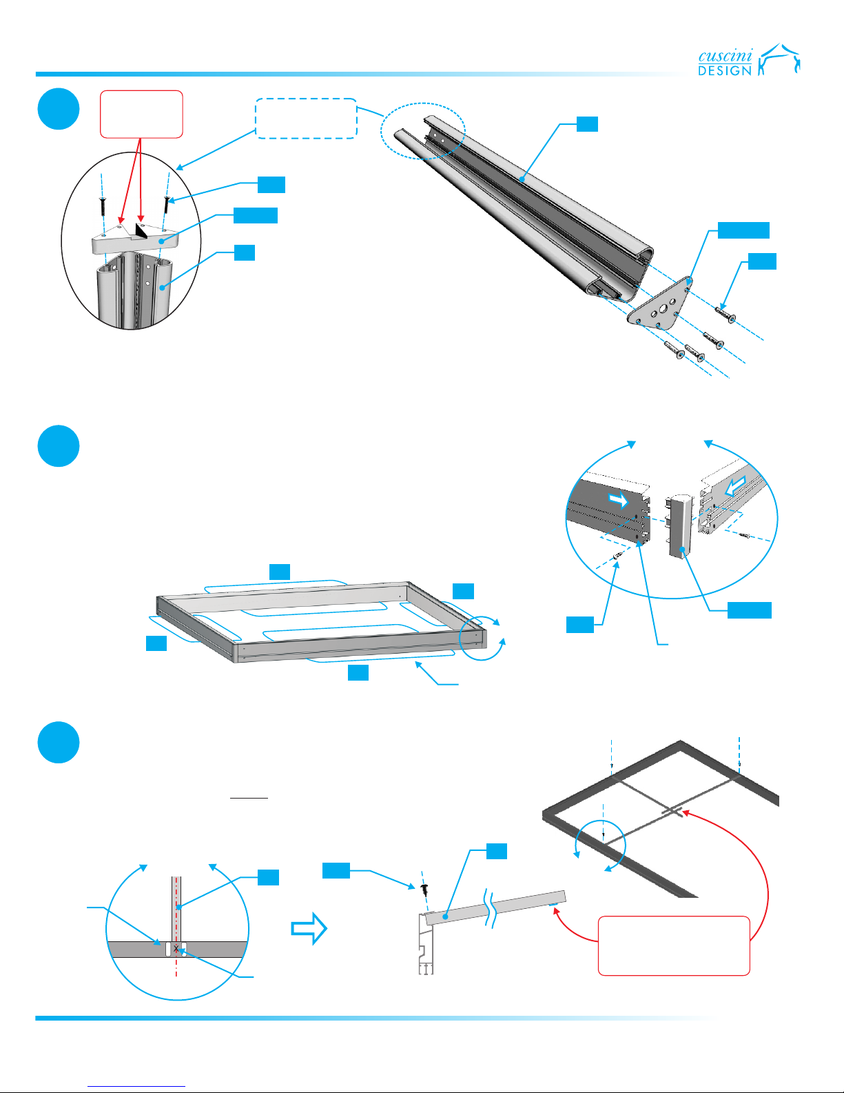
Part List
Metal Screw #8-3/4”
Metal Screw #8-1”
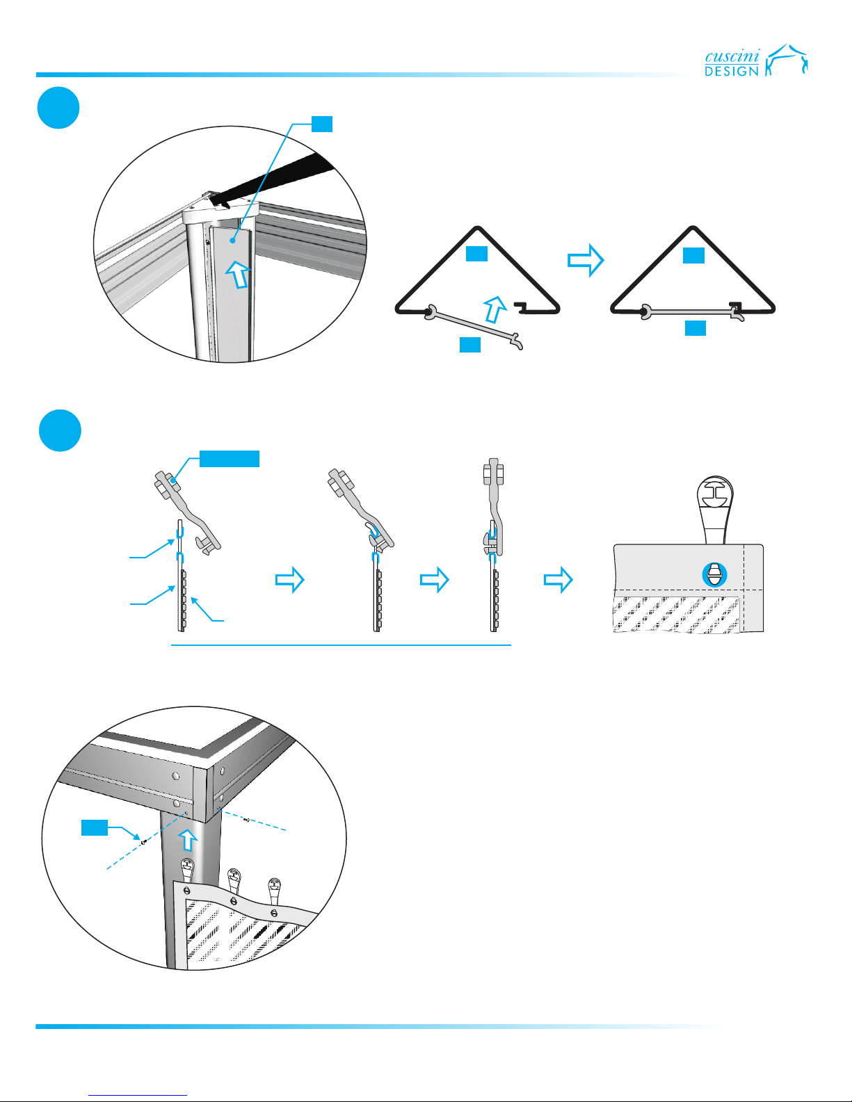
Plastic Corner Beam Inserts
Cover Screw - 1/4” x 1-3/4”
Corner Post Top Cover
KC01
Post End Plate
Plate Screw 1/4” x 1-3/4”
16x 002
KC09
KC06
Carriage Bolt - 5/16” x 2”
5/16” x 1-1/2" Flat Washer
16x 003
16x 007
16x 012
4x PL014
8x 002
5/16” Nylon Lock Nut
KC04
4x PL102
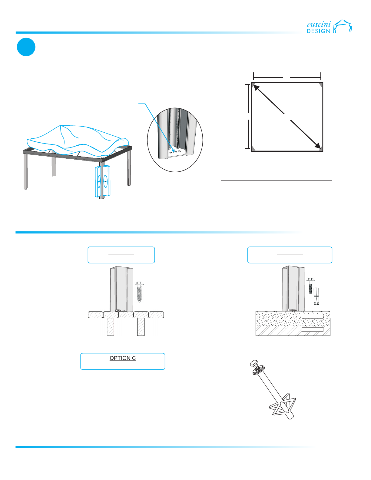
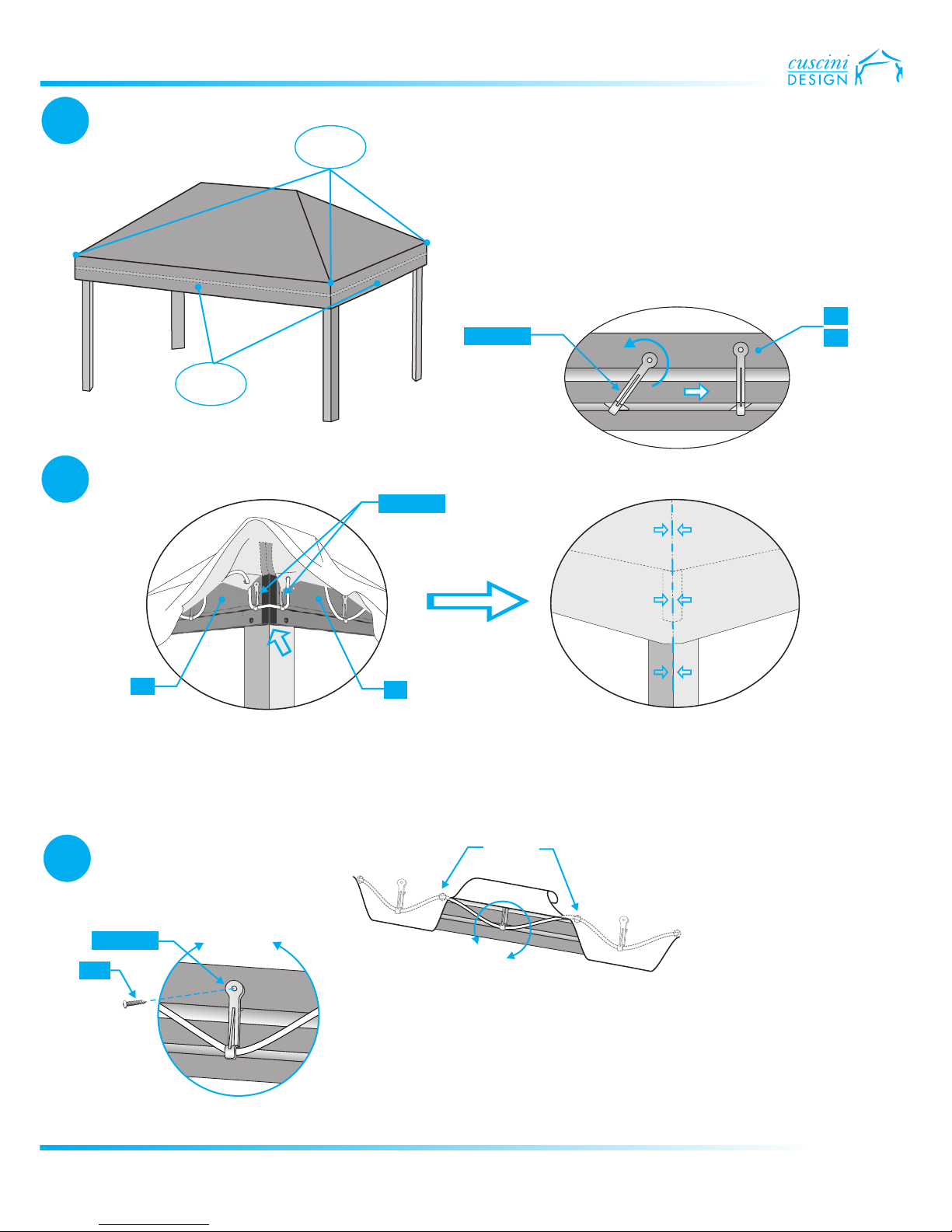
Roof Cover
Hook
#8 Square Head Screwdriver Bit*
#10 Square Head Screwdriver Bit*
* Provided for European countries only
Pulleys included
with curtains
Velcro Strips (shipped with decorative curtains)
8x 025
8x 013
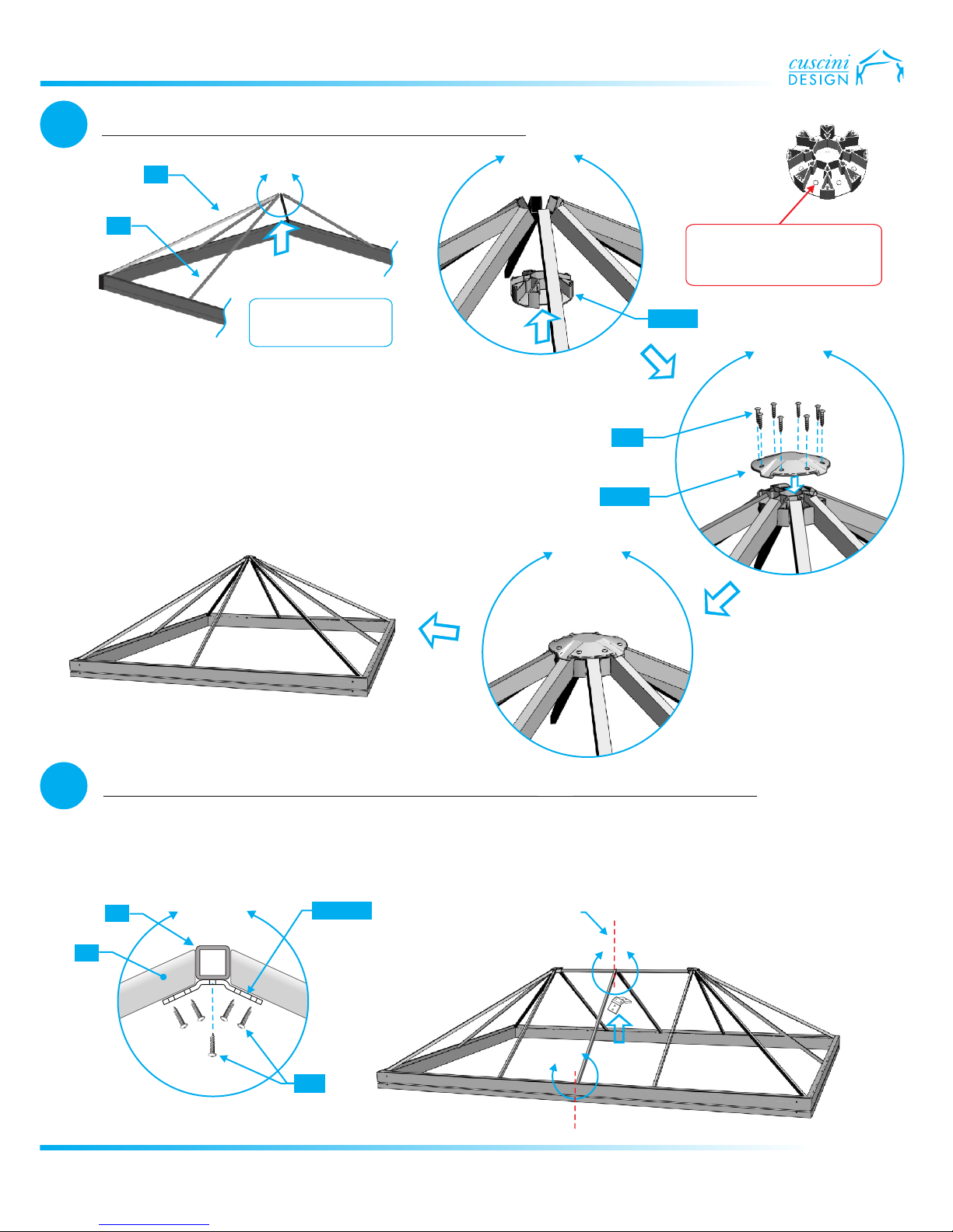
Joint Cover Screw #7-3/4”
Joint Cover Screw #7-3/4”
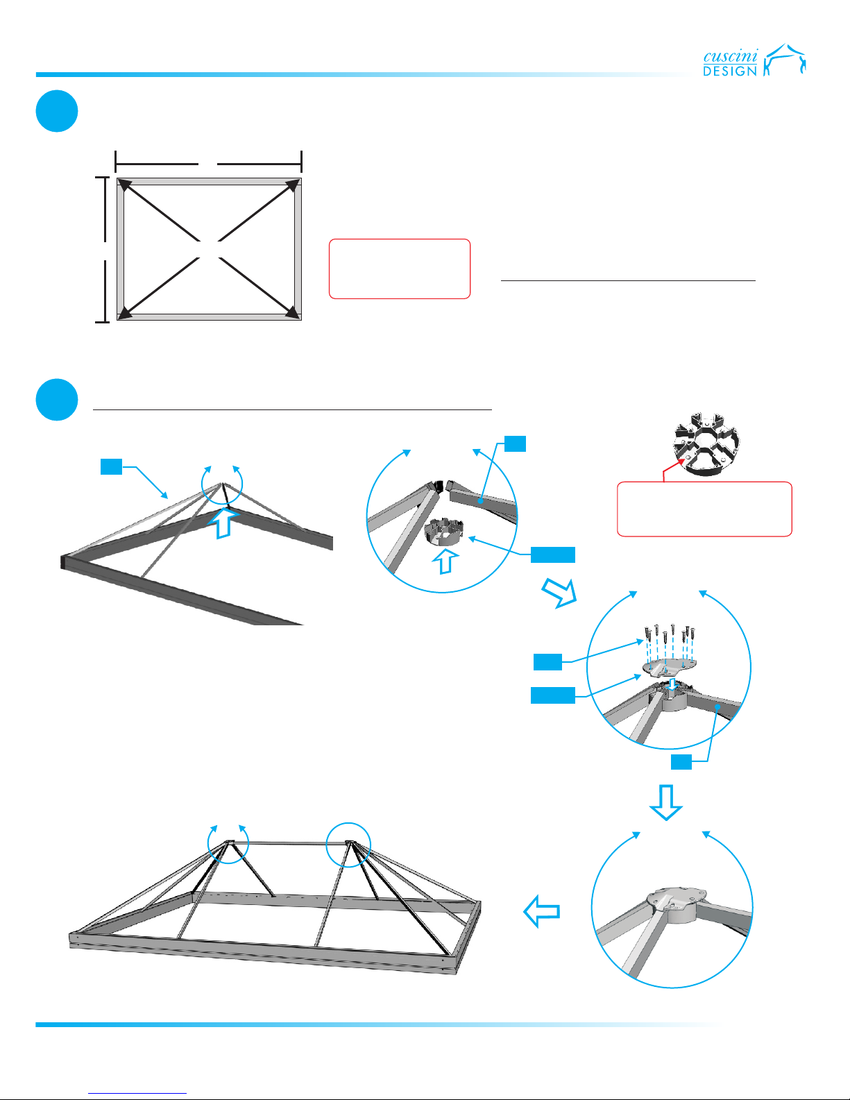
Roof Joint
Box (2 pieces)
Roof Joint
Box (2 pieces)
Bottom
Bottom
Top
Top
Self-tapping Screw #8-3/4”
Self-tapping Screw #8-3/4”
6x 040
4x 040
KC10
16x 062
8x 062
2x PL104
1x PL105
Supplied with rectangular models
KC21 Supplied with square models
12’ or 14’ Side Beam
10’ Side Beam
10’ Side Beam
Triangular Corner Post
Corner Post Cover
2x B1
2x B2
4x B2
4x P1
4x P2
6x S1
4x S1
4x S2
4x S2
1x S3
Roof Corner Spoke (punched hole at one end)
Roof Corner Spoke (punched hole at one end)
Roof Side Spoke (punched hole at one end)
Roof Side Spoke (punched hole at one end)
Roof Middle Support Spoke (both ends with punched holes)
Supplied with rectangular models
Supplied with square models
Mid Roof Support
2x S4
Mid Roof
Support Bracket
Self-tapping Screw #8-3/4”
Self-tapping Screw #8-1”
KCLA3003
Supplied with extended models
6x 040
4x 072
LA3003
1x
DIVERS
4x 005 9/32” x 5 Flat Washer/8”
K.PL101
K.APL001
K.PL106
4x LA3002
Self-taping Screw #8-3/4”
040
of 10
www.cuscini-design.com