Cuttermasters ACG-1450 User manual

SAFETY INSTRUCTIONS
AND OPERATOR’S MANUAL
FOR
ANNULAR CUTTER
REGRINDING
MACHINE
ACG-1450
Cuttermasters
NY, USA –ON,
Canada
(800) 417-2171
(613) 523-7753
Email: cutter[email protected]om
www.
cutt
e
rmasters.com

TABLE OF CONTENTS
I
DESCRIPTION ..............................................................................................3
1.
Directed use...................................................................................................3
2.
Description of work ........................................................................................3
3.
Technical data................................................................................................3
4.
Equipment......................................................................................................4
II. GENERAL SAFETY ADVICE ........................................................................5
1. User’s duty ....................................................................................................5
2. Basic safety advise .......................................................................................5
3. Demands for operators .................................................................................6
4. Special risks ..................................................................................................6
III. INSTALLATION .............................................................................................7
1. Work environment..........................................................................................7
2. Before first installation....................................................................................7
IV. TRANSPORTATION AND STORING............................................................8
V. OPERATION..................................................................................................9
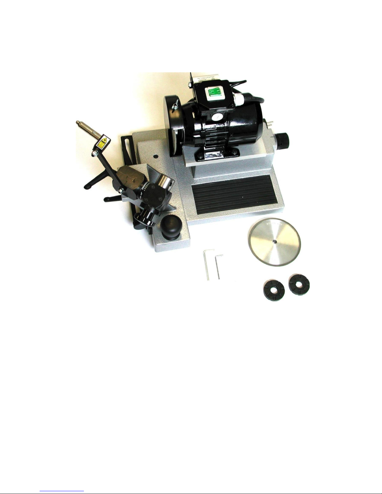
1. Components description ...............................................................................9
2. Adjusting and configuration..........................................................................10
2.1 Dividing disc exchange ......................................................................10
2.2 Core drill adjusting..............................................................................11
3. Regular work................................................................................................12
3.1 Cutter Tooth re-sharpening ..............................................................13
3.2 Cutter Gullet surface grinding............................................................17
4 Grinding disc replacement ..........................................................................19
VI. MAINTENANCE AND REPAIR....................................................................20
1. Cleaning and greasing ................................................................................20
2. Repair .........................................................................................................20
VII. EC DECLARATION OF CONFORMITY......................................................21
VIII. MACHINE TEST CERTIFICATE.................................................................22
IX. WARRANTY CARD...................................................................................23
Cuttermasters
NY, USA –ON, Canada •(800) 417-2171 •(613) 523-7753
www.
cuttermasters.com

I.
DESCRIPTION
1. Directed
u
s
e
ANNULAR CUTTER REGRINDING MACHINE ACG-1450 is specifically designed
for re-sharpening HSS core drills. Machine is not recommended for any other
applications.
In the case that the ACG-1450 is used for any other purpose, then safety cannot be
assured. In such case the operator is responsible for any machine’s damage or injury
of people in the vicinity. Manufacturer recommends to read manual user very
carefully, especially points regarding basic safety advice.
2.
Description
of
w
or
k
The ACG-1450 enables easy core drills (annular Cutter) re-sharpening. Because of
it’s solid and precise construction, low supply energy demand and small dimensions
the machine can be used in any place and can be installed ready for use in a short
time. The ACG-1450 was designed as user friendly machine, and our operator
manual describes how to make simple work of regrinding Cutters.
3. Technical
d
a
t
a
Dimensions LxWxH. [mm]
18 x 16 x 14
Weight Net [kg]
44 Pounds
Supply [V]
110V V AC
Motor [V / amps / rpm.]
110 / 12 / 2600
Movement
length
Motor guide
2.755
Guiding slide
6.377
Noise level dB(A)
<70
Grinding disc inert time [s]
10
Grinding disc
Electroplated, CBN grinding disc ø 5 inch
Diamond Available
Cutter’s clamping [mm]
19 (Weldon shank)
Insulation class
Ι
Max cutter’s length
2 inch
Scope of the cutter’s diameter
Ø 9/16 - ø2.0 inch
Cuttermasters
NY, USA –ON, Canada •(800) 417-2171 •(613) 523-7753
3
www.
cuttermasters.com

4. E
qu
i
p
m
e
n
t
The Annular Cutter Regrinding Machine ACG-1450 is delivered to the customer in
carton packing, ready to use. The machine is completed with standard equipment,
below:
- set of dividing discs
- hexagonal keys s=2,5 and s=4,
- grinding disc for tool flank (Gullet) grinding
- grinding disc for cutting surface (Cutting Egde) grinding
- Operators Manual with warranty card.
Cuttermasters
NY, USA –ON, Canada •(800) 417-2171 •(613) 523-7753
www.
cuttermasters.com

Cuttermasters
NY,
USA-ON,
Canada •(800)
417-2171
•(613)
523-7753
www.cuttermasters.com
5

II. GENERAL SAFETY
A
DVICE
1. Operators
du
t
y
The ACG-1450 machine was designed and made after risk level analysis and after
selection of current harmonized standards in conformity with further technical
specifications. Safety operating is ensured only if operator follows with further
directions.
The operator has to pay special attention and be sure that:
•
Machine is used as directed
•
Machine is efficient,
•
All elements strictly joined with safety work are regularly controlled
•
Personal protection equipment is efficient and always available
•
Operators manual is always close to the machine
•
None of safety and warning label is removed from the machine.
2. Basic safety a
d
v
i
c
e
Operators Manual shall be kept always close the machine in readable condition and
available for any person operating with machine. In addition, the users own company
instructions regarding security and health requirements have to be available for
operators.
Symbols placed on the machine point out that there is a danger to human life and
health. Labels placed on the machine have to be kept in good readable condition
Damaged or not readable labels stall be replaced immediately.
Always wear safety glasses during machine work.
Grinding dust can be danger for your eyes.
Cuttermasters
NY, USA –ON, Canada •(800) 417-2171 •(613) 523-7753
www.
cuttermasters.com

Remove of the grinding disc protection is only permissible for
disc replacement. Protective shroud mustalways be in place during
operation.
Cuttermasters
NY, USA –ON, Canada •(800) 417-2171 •(613) 523-7753
www.
cuttermasters.com
7

Before grinding disc replacement or machine displacement always
disconnect it from electric supply.
WARNING!!! LASER. Machine ACG-1450 is equipped with laser.
In order to avoid eye injury laser CANNOT be directed into the
human eyes.
3. Operating requirements
Only people familiar with this Operators manual, can be allowed to work with ACG-
1450 core drill grinding machine. Any operator who did not get to know this
operators manual contents before starting the machine, maintenance or service,
may cause a dangerous situation for the user’s and neighbouring persons safety.
Do not operate the machine whilst being under the influence of alcohol.
4. Special
r
i
sks
Before start up:
•
Check for any visible damages. Defects must be removed immediately.
•
Machine can work only when is in 100% efficient
•
Do not start machine if some damages or lack of equipment are observed
•
Do not start machine in vicinity of flammable materials or in vicinity of fuel
vapours.
•
Check up regularly power supply cord.
- Repair open electrical connections,
- Replace electric cables immediately if damaged,
- Never clean up electric equipment with water
•
Do not dismantle safety protection elements
Machine modification
No modifications of the machine are allowed. Only original parts should t be used in
order to replace some spare parts and accessories. Mentioned spare parts are
constructed only for this machine. Read the chapter “General Safety Advice”
Cuttermasters
NY, USA –ON, Canada •(800) 417-2171 •(613) 523-7753
www.
cuttermasters.com

III.
INST
A
LL
A
TION
1. Work e
n
v
i
ro
n
m
e
n
t
Use ACG-1450 machine only in dry rooms
Environment temperature +5° ÷ +50° ·C
Humidity max. 90% (protect against condensing)
Place machine on solid bench
Pay attention for safe machine placing
Machine’s work place has to ensure a vibration free motor work
To avoid machine’s damage and series injury when starting the
machine, following steps are necessary to be taken:
Ensure that all parts and tools which not consist the machine
( allen keys, screws) are removed from machine vicinity.
Check condition of grinding disc.
Read also the chapter”General Safety Advice”
Always wear safety
g
l
asses
.
2. Check before first
i
n
s
t
a
ll
a
t
i
on
•
Check the condition of electric connections, and in case of extension cord wear,
check up the condition above. In the case of any damage, the cord should
be immediately replaced. This operation must be carried out by qualified
electrician or in a certified service point.
•
Check connections
•
BesurehemachineisconnectedtothecorrectvoltageCheck if the electric
parameters with this manual and on the machine’s name plate.
Cuttermasters
NY, USA –ON, Canada •(800) 417-2171 •(613) 523-7753
www.
cuttermasters.com
9

Wa
r
n
i
ng
!
•
Check up if slide way moves without excessive frictional
resistance. Machine can be only connected to the net equipped with
earth protective pin. In case of non correct connection of grinding
machine an electric shock may occur.
•
In case, the plug does not suits to the socket, a qualified
electrician intervention is necessary, in order to fit the plug and the
socket. Any wilful exchanges in electric circuit of grinding machines
are permissible.
Cuttermasters
NY, USA –ON, Canada •(800) 417-2171 •(613) 523-7753
www.
cuttermasters.com

Never start the machine if some equipment element is missed, or machine is not
carefully assembled. Not respecting this prohibition may cause the accident and
serious injury. Avoid fingers contact with grinding disc, or other dangers in case the
grinding disc pushes away from the shaft.
IV. TRANSPORT AND
STORING
Storing conditions
Machine is delivered in original factorypacking. We recommend for long-term storing
to keep machine in dry surroundings in factorypacing, in temperature from -20° C do
50° C.
Transport conditions
Machine is designed for hand loading and transporting in work place. For long
distances can be transported by any transport medium. Please take care of you to
prevent the machine’s movement on slide ways under inertial force.
Before machine displacement:
•
Turn off machine with button on position”0”
•
Pull out the power cord from the socket
•
Check up the condition of screws elements.
•
Carry over the machine holding the machine’s base with both hands
Wa
r
n
i
ng
!
In any case:
•
Do not use power cord to move the machine
•
Do not carry over machine with rotating grinding
machine
-in order to change the machine’s position.
disc when replacing the
•
Avoid contact with the disc guard, adjusting elements and laser indicator body.
Cuttermasters
NY, USA –ON, Canada •(800) 417-2171 •(613) 523-7753
www.
cuttermasters.com
11

V.
OPER
A
TION
1.
Components
d
esc
r
i
p
t
i
on
1. Motor
2. Motor feed screw
3. Laser
4. Motor switch
5. Grinding disc guard fixing
6. Grinding disc guard
7. Laser arm
8. Motor slide way
9. Wellhead support
10. Core drill holder support
11. Dividing disc
12. Support slide way
13. Star wheel with screw
14. Bumper handle
15. Micrometric screw
16. Weldon Arbor 19,05mm
Cuttermasters
NY, USA –ON, Canada •(800) 417-2171 •(613) 523-7753
www.
cuttermasters.com

2.
Adjusting
and
c
on
f
i
gu
r
a
t
i
on
2.1.
Dividing
disc e
xc
h
a
n
ge
Dividing discs (point 6.1. pos. 11) of ACG-1450Grinding machine are
responsible for
accurately re-sharpening of core drill depending on the number of teeth. The basic
equipment of machine consist of following dividing disc: T - 8 for core drills with 4 or 8
teeth, T - 10 for core drills with 5 or 10 teeth, and T - 6, T - 7, T - 9, (for core drills
with 6, 7, 9 teeth).
Dividing disc exchange
Choose the dividing disc suitable for the number of
core drill teeth. In order to exchange the dividing
disc, first turn the star wheel in CW direction until the
fixing screw (a) appears in upper position. Tight the
bolt (b) with hex key 2,5. Untighten the screw with
star wheel (pt 6.1. pos. 13) in CCW direction
Untighten screw (a) on dividing disc (use hex key
2,5)
and pull out the disc.
Dividing disc assembly
Place the chosen dividing disc on the spindle. It is
important to draw attention, that screw (a) appears
under the spindle slot (see drawing.). Screw gently
the screw (a) with hex key 2,5) to position the slot
(do not tighten). Tight the screw with star wheel in
CW direction. Next tight screw (a) placed on dividing
disc and loosen the screw (b) (upper drawing).
Cuttermasters
NY, USA –ON, Canada •(800) 417-2171 •(613) 523-7753
www.
cuttermasters.com
13

2.2. Core drill a
d
j
u
s
t
i
ng
rs
Warning! Edges of core drills are sharp. Please avoid injury!
Turn the arbor holder onto position 90 ° (see
drawing.)
When placing the core drill inside the arbor,
please draw your attention the fixing screw
locates with the cylindrical surface of Weldon
shank ( not flat surface) of the core drill. (Do
not tighten the screw). This is necessary to
avoid the core drill position change during
screw tight, what could result incorrect set up.
The laser ray enables core drill accuracy
positioning in the arbor (right drawing) .
Wheel head support (pt 6.1. pos. 9) has got
white line (see drawing). During laser ray
positioning, its light must be always on this line
Cuttermaste
NY, USA –ON, Canada •(800) 417-2171 •(613) 523-7753
www.
cuttermasters.com

located . This is the method of basic laser
beam positioning or its new positioning.
Cuttermasters
NY, USA –ON, Canada •(800) 417-2171 •(613) 523-7753
www.
cuttermasters.com
15

Cuttermasters
NY, USA –ON, Canada •(800) 417-2171 •(613) 523-7753
www.
cuttermasters.com
pe
per
ra
at
tor
or’
’s
s ma
man
nu
ua
al
l fo
for
r A
Annu
nnul
lar
ar Cu
Cut
tt
te
er
r Gr
Gri
ind
ndi
ing
ng Ma
Mac
ch
hi
ine
ne AC
ACG
G-
-1450
1450
12
12
With the spindle of laser indicator guiding, set up laser indicator, to fit exactly to the
external cutting edge (see drawing).
Laser ray is switched on by small button placed on cylindrical indicator’s body. Now
the user should turn the cutter slightly in the arbor, in order that the laser ray lights up
exactly the on the external cutting edge . Fix the cutter in this position tightening the
screw, placed on the cylindrical surface of Weldon arbor with hex key 4.
!! MARK THE POSITIONED TEETH WITH THE MARKER!
3. Regular
w
or
k
Always wear glasses during re-sharpening works.
There are two tooth forms of core drills. Core drills with flat tooth and with V-shape
tooth. Standard type core drills are V shape tooth. Non-standard core drills are
equipped alternately with flat and V-shape tooth. This machine is designed to re-
sharpen in first line tooth on internal side and next on external side. In case of non-
standard core drill re-sharpening first are re-sharpen V-shape tooth and next flat
tooth.

3.1. Core drills
r
e-
s
h
a
rp
e
n
i
ng
Core drills, although available in two sorts are manufactured by different
manufacturers.
If core drills manufacturer provides user with information regarding re-sharpening
Parameters of tool, it is recommended to apply this settings. The following data
below gives a guide only of the required angle settings
Tooth no
HSS Steel
Support Scale
Arbor angle
Surface
Intern.
Extern.
Intern.
Extern.
4
20°
7,5°
7,5°
15°
5
20°
7,5°
7,5°
15°
6
20°
7,5°
7,5°
15°
7
20°
7,5°
7,5°
15°
8
20°
7,5°
7,5°
15°
9
20°
7,5°
7,5°
15°
10
20°
7,5°
7,5°
15°
11
20°
7,5°
7,5°
15°
12
20°
7,5°
7,5°
15°
Operator’s manual for Annular Cutter Grinding Machine GRN1
13

Core drill setting for internal surface re-sharpening
Cuttermasters
NY, USA –ON, Canada •(800) 417-2171 •(613) 523-7753
www.
cuttermasters.com

First step.
Set up the angle on wheel head support at 20 °
Set up the arbor angle at 7,5 °
!! Remember to use the correct dividing disc !!
After both angles settings, move the cutter with the guide and motor feed mechanism
to the grinding disc. Re-sharpen the tooth which is directed into the middle of grinding
disc, nearest to the “3 o’clock” position. (This one which position was settled up with
the laser ray and marked with the marker).
Move the support up to the tooth contact with the grinding disc. Lock the handle of
the bumper in this position (see drawing).
With micrometric screw move back the guide slightly, just so the grinding disc did not
touch the next tooth.
Start re-sharpening the tooth from internal surface, mowing the guide forward and
backwards. Motor feed should be realised carefully and with the same value for all
teeth.
After the first tooth re-sharpening , move back the guide and turn the star wheel in
CW direction until the dividing disc will match the next position. Do not change the
motor feed setting. Repeat above work until all teeth will be re-sharpened.
Operator’s manual for Annular Cutter Grinding Machine GRN1
15

Core drill setting for external surface grinding
Cuttermasters
Set up the angle 7,5 °on
wheel head support
Set up the 15 °angle on
arbor
NY, USA –ON, Canada •(800) 417-2171 •(613) 523-7753
www.
cuttermasters.com
Table of contents