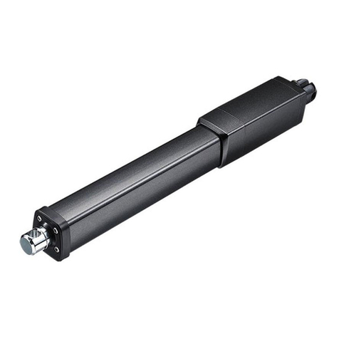
Timotion MA2 User manual

User Manual-MA2
Version D January 2021
1 of 24
1
A
User Manual
MA2

User Manual-MA2
Version C January 2021
2 of 24
2
Contents
Contents .....................................................................................................................................................................2
Glossary .....................................................................................................................................................................3
1. General.................................................................................................................................................................4
About this manual ................................................................................................................................................................... 41.1
Target Personnel ..................................................................................................................................................................... 41.2
Warranty.................................................................................................................................................................................... 41.3
Transport and storage............................................................................................................................................................ 41.4
Packaging ................................................................................................................................................................................. 51.5
Support ...................................................................................................................................................................................... 51.6
Disclaimer ................................................................................................................................................................................. 51.7
Notification and warnings...................................................................................................................................................... 51.8
Mounting/dismounting the actuator...................................................................................................................... 51.8.1
Operation..................................................................................................................................................................... 51.8.2
Equipment power off ................................................................................................................................................ 61.8.3
Duty cycle.................................................................................................................................................................... 61.8.4
Temperature............................................................................................................................................................... 61.8.5
2. Installation ...........................................................................................................................................................7
Mechanical installation........................................................................................................................................................... 72.1
Mounting notice......................................................................................................................................................... 72.1.1
Manual drive operation............................................................................................................................................. 82.1.2
Outer tube reed sensor adjustment ....................................................................................................................... 92.1.3
Electrical installation .............................................................................................................................................................102.2
Important notice ......................................................................................................................................................102.2.1
Cable ..........................................................................................................................................................................112.2.2
Inrush current ...........................................................................................................................................................122.2.3
Wiring definition .....................................................................................................................................................................132.3
Limitations for limit switches output signals .....................................................................................................132.3.1
Two limit switches to cut the current (without signal output) ........................................................................142.3.2
Two limit switches to cut the current and an additional limit switch for signal output .............................152.3.3
Two limit switches to cut current and send signal ...........................................................................................162.3.4
Two limit switches and a single Hall sensor ......................................................................................................172.3.5
Two limit switches and double Hall sensors......................................................................................................182.3.6
Two limit switches and POT..................................................................................................................................192.3.7
Two limit switches with POT to cut the current and an additional limit switch for signal output............202.3.8
3. Product specifications........................................................................................................................................22
2D drawings............................................................................................................................................................................223.1
Ordering key............................................................................................................................................................................233.2
4. Troubleshooting .................................................................................................................................................24

User Manual-MA2
Version C January 2021
3 of 24
3
Glossary
The following terms and acronyms are being used in this manual.
Vm+: The positive pole of power input.
Vm-: The negative pole of power input.
RPM: Number of turns per minute.
AWG: American wiring gauge.
LS: Limit switch installed inside the outer tube.
Up LS: Upper limit switch is installed in fully extended end of stroke.
Low LS: Lower limit switch is installed in fully retracted end of stroke.
Mid LS: Middle limit switch is installed and the position is set by customer’s request.
N.C.: It is the pin of limit switch which is normally short circuit and changed to open when the switch is
triggered.
N.O.: It is the pin of limit switch which is normal open and changed to short circuit when the switch is
triggered.
C.: It is the common pin of limit switch when the circuit is either open or short.
Vp: The reference voltage input to POT signal.
Vout: The POT signal wire output value.

User Manual-MA2
Version C January 2021
4 of 24
4
1.General
About this manual1.1
This user manual is provided to the manufacturer of the equipment or system rather than end users. This
manual provides information needed to install, use and maintain the TiMOTION products. Manufacturers are
responsible to provide a user guide to the end users using the relevant safety information passed from this
manual.
This manual contains installation directions as well as technical data for the TiMOTION industrial electric
linear actuators. Carefully read through each section of the user manual before the equipment is unpacked,
installed or operated. Please note all the dangers, warnings, cautions and notes stated in this manual. Please
follow the instructions provided in this manual to ensure safe, reliable operation.
Target Personnel1.2
Please allow qualified mechanical and electrical professionals to perform all installation, maintenance and
replacement of the TiMOTION products. Please keep the products away from people who do not have the
required experiences or knowledge of the product.
Warranty1.3
In general, TiMOTION provides a 24-month warranty on Industrial Motion actuators based on the
manufacturing date. The warranty is valid only if the equipment is properly operated and maintained correctly.
The application of the product is the responsibility of the buyer. TiMOTION makes no representation or
warranty as to the product's suitability for any particular use or purpose.
Transport and storage1.4
The actuator should only be stored and transported in the original TiMOTION packaging. The temperature
during transportation and storage must be between -40 to +85°C (-40 to +185°F). Please avoid shocks to
the package. If the package is damaged, check the actuator for visible damage and notify the carrier and
TiMOTION.

User Manual-MA2
Version C January 2021
5 of 24
5
Packaging1.5
The sample order packaging contains the product and the QR code directly to this manual. For large quantity
orders, packaging may vary, and TiMOTION reserves the right to change it.
Support1.6
If any technical support or information is needed for this product, please contact your TiMOTION sales
engineer. You can also visit https://www.TiMOTION.com/en for the product or contact information.
Disclaimer1.7
This user manual has been written based on our current technical knowledge. TiMOTION is continuously
working on updating the product information. We reserve the right to carry out technical modifications.
Notification and warnings1.8
Mounting/dismounting the actuator1.8.1
Please read through this user manual before working on the equipment that the actuator is or shall be a
part of.
Adhere to the information contained in this user manual and on the product label. Never exceed the
performance limits stated herein.
Be sure the actuator is not in operation.
Ensure the actuator is free from loads that could be released during mounting or dismounting.
Refrain from unplugging any cables or connectors during operation or while power is on.
Immediately stop using the actuator if it seems faulty or damaged. Notify your TiMOTION sales
engineer so corrective actions can be taken.
Never disassemble the actuator as that will compromise the sealing and could impact the function of
the actuator. Disassembly will lose warranty.
Grease may be present on the extension tube. Contact with the grease is non-hazardous. Please refrain
from removing the film.
Operation1.8.2
Be sure the actuator is correctly mounted as indicated in the user instructions.
Be sure the equipment can be moved easily over the actuator’s whole working area.
Be sure the actuator is connected to a main electricity supply/transformer with the correct voltage
specified on the actuator label.

User Manual-MA2
Version C January 2021
6 of 24
6
Be sure that the connection bolts are secured safely and can withstand the wear.
Stop the actuator immediately if anything unusual is observed.
Ensure there is no side load present on the actuator.
Only use the actuator within the specified working limits.
Refrain from having any contact with the actuator.
Equipment power off1.8.3
Switch off the main supply to prevent any unintentional operation.
Regularly check for extraordinary wear.
Duty cycle1.8.4
The standard-duty cycle is 25%.
If the product is customized, please refer to the approval drawings.
Temperature1.8.5
The operating temperature range is -25°C ~+65°C .
The operational temperature range at full performance is +5°C ~+45°C.

User Manual-MA2
Version C January 2021
7 of 24
7
X X
2.Installation
Mechanical installation2.1
Mounting notice2.1.1
Use solid mounting pins with the proper dimension and support them at both ends.
Note
Correct
Wrong
Please mount the actuator with
the mounting pins of correct
dimension and without threaded at
both ends of the attachments.
Do not mount the actuator with
the pins in different rotated angles,
this could cause stress on the nut
during operation.
The load should act along the
stroke axis of the actuator from
the front attachment, inner tube to
the rear attachment. Off center or
side loads may cause bending and
lead to failure.
Be sure the mounting pins must
be parallel to each other. If the
pins are not parallel to each other
the actuator might be bend and
could be damaged.
X Y

User Manual-MA2
Version C January 2021
8 of 24
8
Manual drive operation2.1.2
In case of a power failure, a manual hand crank can be used.
Before performing, the power supply needs to be disconnected.
When mounting the actuator, ensure there is enough space between the rear adapter and any objects.
This will allow the user override to be operated.
Use the 5mm Allen key for both the IP protection screw and the manual drive shaft inside.
The torque required to manually move the extension tube is within 1.7 Nm, maximum 65 RPM.
Please do not run the outer tube to the end of stroke, as that may damage the actuator.
!
5m
m

User Manual-MA2
Version C January 2021
9 of 24
9
Outer tube reed sensor adjustment2.1.3
The external limit switches are mounted in the two slots at the side of the cover tube.
Use the 2.5mm Allen key inner hexagon to position and lock the reed sensor.
Ensure the reed sensor doesn’t meet other magnetic parts, as this may cause incorrect measurements.
The torque required to secure the screw to fix the reed sensor is within 1.5 Nm
The signal is potential free and independent from the motor power circuit.
Connect the reed sensor with max 32V, <1A.
The reed sensors are N.C..
2.5mm

User Manual-MA2
Version C January 2021
10 of 24
10
Electrical installation2.2
Important notice2.2.1
Make sure the leads/cables leading to the motor are rated to handle the maximum current.
To reduce the chance of a crushing hazard, we recommend an emergency stop.
If you are not using soft stop on a DC-motor, a short peak of high voltage will be sent towards the power
supply. When selecting the power supply, please ensure it is able to withstand the peak of high voltage.
To reduce the chance of interference, refrain from placing signal cables along power cables.
Use a two-wire system to prevent ground loop.
Please use shielded signal cables with applications that can be sensitive or if there is interference risk.
Please note, using long cables in combination with small lead cross-sections and low voltages could
lead to a malfunction due to voltage drop.
Use spark protection on relays and other coil operated devices.
Please be sure the power to the actuator is off before working on the actuator and the wiring.

User Manual-MA2
Version C January 2021
11 of 24
11
φ8.5 mm
Φ2.7 mm
Φ1.8mm
Φ7.5mm
Φ2.7 mm
Signal cable: 20AWG
Power cable: 14AWG
Power cable: 14AWG
Cable2.2.2
The actuator is supplied with a power cable (with/without signal wire). The standard cable, for industrial
applications, has/have flying leads in the end for the user’s equipment connections.
*Please refer to the approved drawing of any customized cable/connector.
Cable without signal:
Cable with signal:

User Manual-MA2
Version C January 2021
12 of 24
12
Inrush current2.2.3
When the actuator starts to work, there is an inrush current to the motor that will be less than 0.2 seconds
(up to four times the rated current).
Please select a power supply that is able to withstand the inrush current. Also, all contacts, including
switches and relay, should be chosen with caution.

User Manual-MA2
Version C January 2021
13 of 24
13
Wiring definition2.3
Below is the standard wiring definition of the actuator. If your actuator is ordered with customized wiring,
please contact TiMOTION sales for detailed information.
Limitations for limit switches output signals2.3.1
In general, the MA2 cable can have a maximum of 6 pins–(2 power wire pins and/or up-to 4 signal wire pins)
The function limitations for limit switches to output signals are shown in the table below:
Function for limit switches
Signal output
Without
POT
Single Hall
Double Hall
2 limit switches to cut the current
OK
2.3.2
OK
2.3.7
OK
2.3.5
OK
2.3.6
2 limit switches to cut the current
one additional limit switch for signal
output
OK
2.3.3
OK
2.3.8
x
x
2 limit switches for signal output
and cut current
OK
2.3.4
x
x
x
* OK = Selectable
** x = Not Compatible
Note:
Please contact the TiMOTION sales engineer if the signal outputs are customized.

User Manual-MA2
Version C January 2021
14 of 24
14
Two limit switches to cut the current (without signal output)2.3.2
The actuator is equipped with two limit switches to cut the current of the motor when the actuator moves to
the end of each stroke and without any output signal.
Wire
AWG
Description
Spec
Red
14
Connect to Vm+ to extend the actuator.
Connect to Vm- to retract the actuator.
24V version: Input voltage 18~32 V DC.
12V version: Input voltage 9~16 V DC.
Black
14
Connect to Vm- to extend the actuator.
Connect to Vm+ to retract the actuator.
Red
Black

User Manual-MA2
Version C January 2021
15 of 24
15
Two limit switches to cut the current and an additional limit switch for2.3.3
signal output
The actuator is equipped with two limit switches to cut the current of the motor when the actuator moves to
the end of each stroke, and an additional limit switch sends out the signal at specific stroke positions.
*Please refer to section 2.3.2 for cut current module.
Wire
AWG
Description
Spec
Red
14
Connect to Vm+ to extend the actuator.
Connect to Vm- to retract the actuator.
24V version: Input voltage 18~32 V DC.
12V version: Input voltage 9~16 V DC.
Black
14
Connect to Vm- to extend the actuator.
Connect to Vm+ to retract the actuator.
White
20
Connect to up limit switch normal closed
pin (N.C.)
The signal is potential free and independent
from the motor power circuit.
The LS opens (N.O. signal) when the
actuator moves to the position where the
additional limit switch is triggered.
The additional limit switch, installed in
position by customer request, is factory
preset and non-adjustable.
Connect the additional limit switch signal
with max 32V, <1A.
Black
20
Connect to low limit switch normal closed
pin (N.C.)
Red
Black
White
Black

User Manual-MA2
Version C January 2021
16 of 24
16
Two limit switches to cut current and send signal2.3.4
The actuator is equipped with two limit switches to cut current of the motor and send signal when the
actuator moves to the end of each stroke.
*Please refer to section 2.3.2 for cut current module.
Wire
AWG
Description
Spec
Red
14
Connect to Vm+ to extend the actuator
Connect to Vm- to retract the actuator
24V version: Input voltage 18~32 V DC
12V version: Input voltage 9~16 V DC
Black
14
Connect to Vm- to extend the actuator
Connect to Vm+ to retract the actuator
White
20
Connect to up limit switch normal closed
pin (N.O..)
The signal is NOT potential free and actively
outputs voltage at each end of stroke.
Both of the white and black signal wire are
normal open circuit when the actuator is in
the middle of stroke.
The signal circuit is connected to motor
power circuit and the value Vm+ depends
on actuator voltage.
Connect the limit switch signal wire to the
load <1A.
Black
20
Connect to low limit switch normal closed
pin (N.O..)
Red
Black
White
Black

User Manual-MA2
Version C January 2021
17 of 24
17
Two limit switches and a single Hall sensor2.3.5
The actuator is equipped with two limit switches to cut the current of the motor when the actuator moves to
the end of each stroke and with a single Hall sensor sending position signal output.
*Please refer to section 2.3.2 for cut current module.
Wire
AWG
Description
Spec
Red
14
Connect to Vm+ to extend the actuator
Connect to Vm- to retract the actuator
24V version: Input voltage 18~32 V DC
12V version: Input voltage 9~16 V DC
Black
14
Connect to Vm- to extend the actuator
Connect to Vm+ to retract the actuator
Red
20
+5V DC input signal power for Hall sensor
board.
Hall sensor output signal type is square
wave with Hi voltage 5V and Low voltage
0V, and with the output current of 0.1A
(please refer to the approval drawing for the
resolution and details).
Hall sensor circuit is independent to motor
power circuit.
White
20
Output Hall sensor signal during the
actuator moves.
Black
20
Hall sensor signal ground.
Red
Black
Red
White
Black

User Manual-MA2
Version C January 2021
18 of 24
18
Two limit switches and double Hall sensors2.3.6
The actuator is equipped with two limit switches to cut the current of the motor when the actuator moves to
the end of each stroke, and with double Hall sensors sending position signal output.
Wire
AWG
Description
Spec
Red
14
Connect to Vm+ to extend the actuator
Connect to Vm- to retract the actuator
24V version: Input voltage 18~32 V DC
12V version: Input voltage 9~16 V DC
Black
14
Connect to Vm- to extend the actuator
Connect to Vm+ to retract the actuator
Red
20
+5V DC input signal power for Hall sensor
board.
Hall sensor output signal type is square
wave with Hi voltage 5V and Low voltage
0V, and with the output current of 0.1A
(please refer to the approval drawing for the
resolution and details).
S1 leads 90 degrees’ phase to S2.
Hall sensor circuit is independent to motor
power circuit.
White
20
Output Hall sensor signal S1 during the
actuator moves.
Blue
20
Output Hall sensor signal S2 during the
actuator moves.
Black
20
Hall sensor signal ground.
S1
S2
Red
Black
Red
White
Blue
Black

User Manual-MA2
Version C January 2021
19 of 24
19
Two limit switches and POT2.3.7
The actuator is equipped with two limit switches to cut the current of the motor when the actuator moves to
the end of each stroke, and with POT position signal output.
Wire
AWG
Description
Spec
Red
14
Connect to Vm+ to extend the actuator
Connect to Vm- to retract the actuator
24V version: Input voltage 18~32 V DC
12V version: Input voltage 9~16 V DC
Black
14
Connect to Vm- to extend the actuator
Connect to Vm+ to retract the actuator
Black
20
POT signal ground.
POT output signal type is the voltage in
proportion to the reference voltage
input, which is relative to the position of
the actuator.
The
recommended power of the POT input is
<2W.
The brand and spec of the
potentiometer embedded is Bourns,
0~10Kohm, 10 turns.
Red
20
POT signal output Vout={r(𝛺) 10𝐾(𝛺)
⁄}Vp
Fully retracted
Fully extended
r = 300~500(𝛺)
r depends on the
configuration
(note)
Note: Users can refer to the drawing for fully
extended resistance details.
White
20
POT reference voltage input Vp, 5~32V
DC (Recommended: 10V).
Red
Black
White
Red
Black

User Manual-MA2
Version C January 2021
20 of 24
20
Two limit switches with POT to cut the current and an additional limit2.3.8
switch for signal output
The actuator is equipped with two limit switches to cut the current of the motor when the actuator
moves to the end of each stroke, and an additional limit switch sends out the signal at specific stroke
positions, along with POT position signal output.
Wire
AWG
Description
Spec
Red
14
Connect to Vm+ to extend the actuator
Connect to Vm- to retract the actuator
24V version: Input voltage 18~32 V DC
12V version: Input voltage 9~16 V DC
Black
14
Connect to Vm- to extend the actuator
Connect to Vm+ to retract the actuator
Brown
20
Connect to middle limit switch normal
closed pin (C.)
The signal is potential free and
independent from the motor power circuit.
The LS opens (N.O. signal) when the
actuator moves to the position where the
additional limit switch is triggered.
The additional limit switch, installed in
position by customer request, is factory
preset and non-adjustable.
Connect the additional limit switch signal
with max 32V, <1A.
Grey
20
Connect to middle limit switch normal
closed pin (N.C.)
Yellow
Green
White
Red
Black
Red
Black
Brown
Grey
White
Red
Black
Table of contents
Other Timotion Controllers manuals
Timotion
Timotion JP4 User manual

Timotion
Timotion TDH2 User manual
Timotion
Timotion TDH8D User manual
Timotion
Timotion TDH15 User manual
Timotion
Timotion TA2P User manual
Timotion
Timotion VN1 User manual
Timotion
Timotion MA1_AC User manual
Timotion
Timotion TDH8P User manual

Timotion
Timotion TDH13P User manual
Timotion
Timotion MA5 User manual
Timotion
Timotion TDH6 User manual
Timotion
Timotion TDH5PR User manual
Timotion
Timotion TBB6 User manual
Timotion
Timotion TA16 User manual

Timotion
Timotion MA1_DC User manual

Timotion
Timotion ADJUSTME TDH3 User manual

Timotion
Timotion TDH4 User manual

Timotion
Timotion TDH6 User manual
Timotion
Timotion MA2T User manual
Timotion
Timotion ADJUSTME TDH3 User manual
