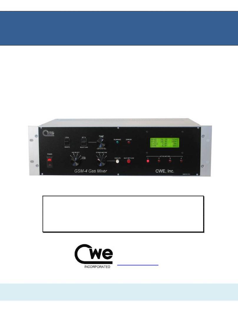
CWE GSM-3 User manual

GSM-3
3-Channel Programmable Gas Mixer
©CWE 2023
Read instructions carefully before operating this device.
This device is not to be used for Human Life Support applications.
To avoid possible electrical shock, do not operate this device if is wet or has had
liquids spilled onto it.
Service or calibration procedures should only be performed by qualified
personnel familiar with the electrical hazards of line-powered devices.
Instruction Manual
www.cwe-inc.com

GSM-3 Gas Mixer Instruction Manual 2
©2023 CWE, Inc.
STATEMENT OF WARRANTY
IF THIS INSTRUMENT FAILS WITHIN A PERIOD OF ONE YEAR FROM THE DATE OF
DELIVERY OR INSTALLATION, CWE, INC. WILL, AT ITS OPTION, REPAIR OR REPLACE IT
FREE OF CHARGE TO THE PURCHASER. THIS WARRANTY EXCLUDES DAMAGE
INCURRED THROUGH ABUSE OR ACCIDENT AND CONSUMABLE ITEMS OR
COMPONENTS SUCH AS BATTERIES. CWE, INC. DOES NOT ASSUME ANY LIABILITY FOR
ANY CONSEQUENTIAL DAMAGES RESULTING FROM THE USE OR MISUSE OF THIS
INSTRUMENT. THIS WARRANTY IS APPLICABLE ONLY TO THE ORIGINAL PURCHASER
OF THE INSTRUMENT, AND IS NON-TRANSFERRABLE.
IF YOU HAVE A PROBLEM
Please call or write describing your problem. We can often identify what is wrong, and suggest a
solution without recourse to returning the device. Defective units under warranty should be
returned to the factory along with a note describing the nature of the fault. Every effort will be
made to ensure prompt repair or replacement of the device.
FACTORY SERVICE
Out of warranty or damaged instruments may be returned to the factory postage prepaid for
service at prevailing rates. Upon request, a written or verbal quotation for such service will be
issued after examination of the unit but prior to commencing repairs or service. Address requests
for service or technical information to:
CWE, Incorporated
Technical Support Department
TEL (610)642-7719
LIFE SUPPORT POLICY
Instruments manufactured by CWE, Incorporated are not authorized for use as critical
components in humanlife support devices or systems. "Life support devices or systems", as used
herein, are devices or systems whose failure to perform, whether through misuse, failure, or
proper operation, can reasonably be expected to result in significant injury to the operator or
subject persons.
USER INFORMATION:
Base Unit Serial Number: _______________
Calibration gas: Channel A________, Channel B________, Channel C________
Flow ranges: Channel A________, Channel B________, Channel C________
GSM-CommVS Software version: __________________
Gas correction factors (see Note): enabled_____ not used_____
NOTE: If gas correction factors (K-Factors) are not used, this indicates the flow controllers for each channel are
pre-calibrated with a specific gas for the highest accuracy.
This document last updated May 26, 2023

GSM-3 Gas Mixer Instruction Manual 3
©2023 CWE, Inc.
TABLE OF CONTENTS
1.0 QUICK START GUIDE..............................................................................................4
2.0 INTRODUCTION.......................................................................................................6
3.0 SETUP......................................................................................................................7
4.0 OPERATION.............................................................................................................7
4.1 CREATING A GAS MIXTURE...................................................................................8
4.2 NOTES ON GAS MIXTURES ...................................................................................8
4.3 INDICATOR LIGHTS.................................................................................................9
4.4 IMMEDIATE ACTION CONTROLS.........................................................................10
4.5 LOCAL / REMOTE SWITCH...................................................................................10
5.0 REAR PANEL CONNECTIONS..............................................................................10
6.0 GAS SUPPLY ERROR DETECTION......................................................................11
7.0 CALIBRATION USING CORRECTION FACTORS.................................................11
8.0 SPECIFICATIONS ..................................................................................................13
9.0 GAS CHARACTERISTICS......................................................................................14
10.0 GSM-CommVS SOFTWARE ................................................................................15
11.0 Appendix A: GSM-3 Communication protocols.....................................................19
12.0 Appendix B: Disabling the Gas Source Alarm Function ........................................21
Figure 1: GSM-3 Gas Mixer front panel...............................................................................6
Figure 2: GSM-3 LCD panel...............................................................................................7
Figure 3: LCD panel showing alarm condition ...................................................................11
Figure 4: GSM-CommVS screen........................................................................................15
Figure 5: Gas selection drop-down menu...........................................................................16
Figure 6: Timed experiment setup .....................................................................................18
Figure 7: GSM-3 Alarm PCB showing Jumper locations......................................................21

GSM-3 Gas Mixer Instruction Manual 4
©2023 CWE, Inc.
1.0 QUICK START GUIDE
This section provides a short guide to setting up and operating the GSM-3 Gas
Mixer. A more detailed description will be found in later sections of this instruction
manual.
Equipment set-up: Place the GSM-3 in a convenient location. If a computer is to
be used for remotely controlling the GSM-3, it should be
located nearby.
Connect the tubing: Connect the compressed gas sources to the gas inlets on the
rear panel. Note that these are “one-touch” press-in tubing
connectors. The gas outlet supplies the mixed gas.
Connect the cables: Connect the serial port cable between your computer and the
and the GSM-3 rear panel connector. If your computer does
not have a serial port, use the supplied USB-Serial adapter.
Install the software: Insert the GSM-CommVS CD in your computer. If the install
program does not auto-start, select run, then browse to
setup.exe on the CD. Follow the instructions to install the
program.
Start GSM-COMMVS: From the start menu, choose programs, and locate GSM-
CommVS. Select it to run the program.
Select config file: A dialog box will open asking you to select a configuration file.
Select default.txt to select a generic configuration file, or
cancel to go directly to the main screen.
Configure COM port: At the bottom of the GSM-CommVS window, set your Comm
port. Many computers will use the default COM1, but yours
may be different. The program will not work if the correct
COM port is not selected!
Set flow ranges: If not already displaying the channel flow ranges (bottom right
of screen), enter them now.
Power up the GSM-3: Turn on the GSM-3 power. After a few introductory
messages, the LCD will display the main screen. Select
LOCAL if you want to begin making settings from the front
panel, or REMOTE if you want to set up the GSM-3 from your
computer.
Ready to go! Using either the front panel controls (local mode) or the
GSM-CommVS software, select the gasses you have
connected to the inlets. Adjust the percentages for each
and set the total flow desired.
Configurations: The GSM-3 allows you to store up to four mixtures, which can
be immediately accessed using the stored mixture knob. The
GSM-CommVS software similarly allows setting up four
mixtures. These sets of mixtures can be saved as
configuration files. Use the configuration menu at the top of
the screen to save or load these files.

GSM-3 Gas Mixer Instruction Manual 5
©2023 CWE, Inc.
Save on exit: Use the exit pushbutton on the screen to close the program.
A dialog box will open, asking you to save a configuration file.
Select an existing file, or create a new one, or select cancel to
exit without saving a configuration file.
Operating tips: Give your configuration files meaningful names to allow easy
retrieval and use in the future. A few sample files are included
as examples.

GSM-3 Gas Mixer Instruction Manual 6
©2023 CWE, Inc.
2.0 INTRODUCTION
The GSM-3 Gas Mixer allows you to easily create accurate, custom gas blends
using up to three different gasses. All parameters (gas type, percent of each gas in
the output mixture, and total flow) can be set using the front panel controls, or can
be set using the provided GSM-CommVS software. The instrument automatically
corrects for different gas densities and other properties when setting the mass flow
controllers.
A typical application of the GSM-3 is to generate gas mixes for hypoxia,
hypercapnia, or other respiratory gas challenge studies. Because these studies
often involve a low concentration of one gas relative to the other gas components,
one GSM-3 flow channel normally uses a different range flow controller. A typical
configuration might be as follows (your instrument may be different):
Note: Each GSM-3 is customized to the user’s requirements
with the appropriate mass flow controllers installed (see page 2
for your configuration). Examples shown in this manual will
probably differ from yours.
Channel:
Nominal Range
Usable Range
GAS 1
0 –10,000 ml/min
250 –10,000 ml/min
GAS 2
0 –10,000 ml/min
250 –10,000 ml/min
GAS 3
0 –1000 ml/min
20 –1000 ml/min
For the best mixture accuracy, any of the channels should be set within the usable
range shown above.
The GSM-CommVS software provided allows the user to save any number of pre-
set configurations for later use. These mixtures can then be downloaded and run on
the GSM-3 itself.
Figure 1: GSM-3 Gas Mixer front panel

GSM-3 Gas Mixer Instruction Manual 7
©2023 CWE, Inc.
3.0 SETUP
Setting up the GSM-3 Gas Mixer is straightforward. The following instructions
assume that a computer with a standard serial port is available.
1. Install the GSM-3 Gas Mixer in a location convenient to the gas sources, and
near the computer that will be used with it. The unit can be rack mounted if
desired.
2. Connect your pressurized gasses to the GAS 1, GAS 2, and GAS 3ports on the rear
panel. These ports require 0.25” (6.35mm) O.D. semi-flexible tubing, which
makes a press-fit connection. To disconnect any of the tubing connections, press
in on the outer ring of the connector and pull out the tubing. Gas pressures
should be in the range of 20 - 75 psi (1.4 –5 bar).
Note: Most GSM-3’s will be configured for specific gasses,
which must be connected to the appropriate inlet.
3. Connect the GAS OUTLET port using the same type tubing, or use one of the hose-
barb adapters included with the system.
4. Connect the supplied serial port cable from your computer to the 9-pin female
RS232 port on the rear of the GSM-3. If your computer does not have a serial
port, install and use the supplied USB-Serial adapter. This adapter will create a
virtual COM port, whose COM number can be located at: Control Panel /
System / Device Manager /Ports (COM & LPT) / USB-Serial COM4
(typical, but your COM port number may be different).
5. Install the GSM-CommVS software on your PC. Insert the CD in your computer,
and run Setup.exe. We recommend accepting the default directories. The
program will then be installed in: C:\Program files\GSMComm.
6. When the GSM-3 is turned on, select LOCAL to set up the instrument from the
front panel, or REMOTE to use the GSM-CommVS software. Be sure to set the
COM port to the actual port used on your computer.
4.0 OPERATION
The instructions below describe the procedure for setting up gas mixtures and
running them from the instrument itself. The operation of the GSM-CommVS
software is described later.
Figure 2: GSM-3 LCD panel

GSM-3 Gas Mixer Instruction Manual 8
©2023 CWE, Inc.
4.1 CREATING A GAS MIXTURE
Be sure the LOCAL /REMOTE switch is set to LOCAL.
Up to four custom gas mixtures can be created and stored in the GSM-3. To create,
edit, or run any of these, use the STORED MIXTURE knob. When any of the stored
mixtures is selected, its current settings will be displayed on the LCD panel.
Selecting gasses –Using the GAS SELECT knob, select either A, B, or C. While
holding the SELECT GAS /SET %switch in the SELECT GAS position, rotate the ADJUST
knob until the desired gas is shown on the display. Perform this procedure to set
gasses A, B, and C.
Note: Most GSM-3’s will be configured for specific gasses for
each of the three channels.
Setting gas percentages –Each gas can be set to anywhere in the 0 –100%
range, with 0.1% resolution. The total should add up to 100%, or the flows will be
inaccurate. The ERROR light will turn on and stay on until the gas fractions add up to
100 percent. To set a percentage, first point to A, B, or C using the GAS SELECT
knob. While holding the SELECT GAS /SET %switch in the SET %position, rotate the
ADJUST knob until the desired percentage is shown on the display. Repeat for the
other gasses. Remember that the total should add up to 100%!
Setting flow –The GSM-3 allows you to set the total flow of the mixture only.
Individual gas flows are computed and shown on the display, but the user cannot
change these directly.
To set the total flow, rotate the SELECT GAS knob to the TOTAL FLOW position. Use
the ADJUST knob to set the flow, which will be displayed on the LCD panel.
Storing the mixture -- After a mixture is configured, press the EXECUTE pushbutton,
which will store the mixture and start it running. Press the SHUT OFF FLOW
pushbutton to stop the flow. The mixture is now stored in non-volatile memory, and
will be available even if the instrument has been turned off, and then on again.
The four stored mixtures can be created and stored as described above, and can be
selected and executed any time the instrument is used.
4.2 NOTES ON GAS MIXTURES
No flowmeter or flow controller is “ideal”; i.e., it does not operate linearly over a
zero –full scale range. The range of operation is known as the turndown ratio. This
is simply the ratio of full-scale to minimum usable range. In the case of the GSM-3
controllers, this turndown ratio is approximately 50:1. For example, a 1000sccm
(standard cc/minute) controller can accurately operate over a 20 –1000sccm range.
The practical result of this information is that all possible combinations of mixtures
and flows may not be accurate if any of the gas channels fall outside of the usable
range for that channel. If any of the computed flows falls below the minimum usable
flow, the TOTAL FLOW should be increased to raise the channel flow above the
usable lower limit. The following example illustrates this condition:

GSM-3 Gas Mixer Instruction Manual 9
©2023 CWE, Inc.
Desired flow mixture, total flow = 1000 ml/min, initial settings:
Channel
Percent of mix
Computed channel flow
GAS 1 (O2)
21.0%
210 ml/min (bad!)
GAS 2 (N2)
78.0%
780 ml/min (good)
GAS 3 (CO2)
1.0%
10 ml/min (bad!)
The flows for GAS 1and GAS 3fall below the minimum (250 and 20 ml/min,
respectively). To obtain an accurate mixture, increase the total flow to move these
individual flows into the usable ranges:
Total flow increased to 2000 ml/min:
Channel
Percent of mix
Computed channel flow
GAS 1 (O2)
21.0%
420 ml/min (good)
GAS 2 (N2)
78.0%
1560 ml/min (good)
GAS 3 (CO2)
1.0%
20 ml/min (good)
If very low flows are routinely required, the GSM-3 can be retro-fitted with flow
controllers for different ranges. Please contact the factory for details.
4.3 INDICATOR LIGHTS
The various indicator lights give important information about the operation of the
GSM-3 Gas Mixer.
Active Mixture lights –These four red LED’s indicate which mixture is currently
selected by remaining steadily on. A blinking ACTIVE MIXTURE led indicates that a
particular mixture is currently running (flow is being delivered). Even while one
mixture is running, the STORED MIXTURE knob can be used to select another mixture
for configuration. In this case, one of the LED’s will be blinking (that mixture is
running), and another is steadily on (indicating that that mixture is being displayed
for editing, etc.).
Running light –This green led will turn on when gas is actually flowing; i.e., a
mixture is currently running.
Error light –This red led will indicate setup errors, such as when the gas
percentages do not add up to 100%.
This will also light when a gas source error is detected (see section 6.0).

GSM-3 Gas Mixer Instruction Manual 10
©2023 CWE, Inc.
4.4 IMMEDIATE ACTION CONTROLS
As described above, the EXECUTE pushbutton will immediately cause the currently
selected mixture to run. Conversely, pressing the SHUT OFF FLOW pushbutton will
immediately shut off the flow controllers.
4.5 LOCAL / REMOTE SWITCH
Set this switch to LOCAL to perform gas mixture setup and execution from the
GSM-3 front panel. Set this switch to REMOTE to use the GSM-CommVS software to
remotely control the instrument. Note that in remote mode, the ACTIVE MIXTURE
LED’s are not automatically on, indicating that the STORED MIXTURE switch setting is
ignored, since this function is performed by the software.
5.0 REAR PANEL CONNECTIONS
Gas Inlets –These ports are used to connect any of the three inlet gasses. The
connectors are compatible with ¼” OD semi-flexible tubing (urethane or similar).
Press in the outer ring of the connector to withdraw the tubing.
Gas Outlet –This port provides the gas mixture created by the GSM-3.
Fuse –In case this fuse blows, replace it with one of the same current and voltage
rating as the original. If the fuse blows repeatedly, the instrument should be
returned for service.
Serial Port –The RS232 serial port uses a standard 9-pin D-sub connection. This
port should be connected to your computer using a straight-wired cable (not a
crossover or modem cable). Use the supplied USB-Serial adapter if a true serial
port is not available.
Analog Outputs –These BNC jacks provide an analog voltage corresponding to
the flow rate of each of the three gasses in the current gas mixture.

GSM-3 Gas Mixer Instruction Manual 11
©2023 CWE, Inc.
6.0 GAS SUPPLY ERROR DETECTION
The GSM-3 monitors the COMMAND signals going to the mass flow controllers, and
the actual flow OUTPUT signals. Theoretically, these should be the same after
allowing for the response time of the flow controllers. If a gas supply to any of the
three channels is disrupted (e.g., a gas tank runs out), the GSM-3 will detect this as
an alarm condition.
Note: In cases where one or more channels are deliberately not
connected or used, no error will be detected.
Figure 3: LCD panel showing alarm condition
When a gas source error is detected, here is what happens:
1. The ERROR led will light, and the LCD display will appear as above.
2. The “CHECK GAS SOURCE” prompt is followed by the gas channel that is
causing the error.
3. A series of beeps will sound, alerting the operator to an error condition.
4. The beeps will stop after three errors have been detected, but the alarm display
and ERROR led will persist.
5. If no error condition is detected for 45 seconds, the message and ERROR led will
clear.
6. You can immediately clear the error display by briefly pressing the ADJUST knob.
7.0 CALIBRATION USING CORRECTION FACTORS
When using the GSM-3 with gasses other than nitrogen, correction factors (also
called K-factors) are used to correct for the density, viscosity, and other
characteristics of the gas. These factors are automatically applied when you select
a gas, either from the front panel or using the GSM-CommVS software.
Note: Most GSM-3’s will be configured for specific gasses,
which must be connected to the appropriate channel. These
mass flow controllers are factory calibrated using the actual
gasses, and DO NOT use correction factors.
Although flows generated using these correction factors are generally accurate to
within +3%, you can adjust them to provide the best accuracy under the specific

GSM-3 Gas Mixer Instruction Manual 12
©2023 CWE, Inc.
laboratory conditions of the user. The procedure described below explains how to
do this.
1. Set up and run a gas mixture using the gas you want to calibrate. For example,
5.0% CO2, 95% nitrogen.
2. Switch to LOCAL CONTROL.
3. Monitor the actual output concentration of the target gas (CO2).
4. Press the ADJUST KNOB to display the “Adjust K-factor” menu:
5. Rotate the ADJUST KNOB until the desired gas is displayed:
6. When the target gas is shown, press the ADJUST KNOB. The following screen will
appear, showing the current K-factor for that gas:
7. Rotate the adjust knob to increase or decrease the displayed K-factor. Increasing
it will cause a higher flow of that gas at the outlet, and decreasing it will result in a
lower flow. In the example above, if a 5.0% CO2mixture is set up, but the actual
measured concentration reads 4.6%, try increasing the K-factor by 13 (about 8%)
to 180. After making this change, press the ADJUST KNOB to accept and store this
change. The GSM-3 will re-start, and apply the new K-factor.
8. After re-starting, the previously run test gas mixture should be displayed. Run it,
and note the output gas concentration. If the concentration still needs
adjustment, repeat the above procedure activated by pressing the ADJUST KNOB.
After this procedure is completed, the K-factor is stored and will be applied
automatically whenever the GSM-3 is used.
Set gas K-factor
Select gas: AIR
SHUT OFF to exit
KNOB to accept
Set gas K-factor
Select gas: CO2
SHUT OFF to exit
KNOB to accept
Set gas K-factor
CO2 K = 167
SHUT OFF to exit
KNOB to accept

GSM-3 Gas Mixer Instruction Manual 13
©2023 CWE, Inc.
8.0 SPECIFICATIONS
Flow controller type...................................................... thermal mass flow controllers
Linearity (0 - 100%) ........................................................................................... +1%
Repeatability and hysteresis ........................................................................ +0.15%
Long-term stability ................... +0.2% full scale / 7500 hours continuous operation
Response time .............................................................................. <1 second, typical
Operating temperature.................................................................................. 0 - 50oC
Operating pressure range (25psi calibration pressure) ..............................0 –100psi
Usable flow range (Note1) ................................................ 0.02 –1.0 x controller range
Analog outputs (for Gas 1, Gas 2, or Gas 3).............. 5.0V for channel full scale flow
Analog output connectors (rear panel)........................................................BNC jacks
Serial communication format .............. 19,200 baud, 8 data bits, no parity, 1 stop bit
Serial output connector (rear panel) ....................................................... DB9 female
Gas inlet and outlet connections ....................... ¼” One-Touch press-in connectors
Dimensions ........................................................................... 19W x 5.25H x 12D in.
Power requirements......................................................115/230V (switchable), 50VA
Note1: Actual flow depends on flow controllers installed in your system.

GSM-3 Gas Mixer Instruction Manual 14
©2023 CWE, Inc.
9.0 GAS CHARACTERISTICS
If not otherwise noted, the mass flow controllers used in the GSM-3 Gas Mixer are
calibrated using nitrogen. Different gasses can be used by employing “K Factors”,
which are constants that correct for the densities of gasses relative to nitrogen.
These correction factors are automatically applied when different gasses are used
with the GSM-3 Gas Mixer. In case your gas is not one of those programmed into
the instrument, you can choose among the pre-programmed gasses one that has
similar characteristics to your gas. This way, the mixture will remain accurate.
Gas No.
Programmed gas
Symbol
Stored K-factor
K-Factor
1
Air
AIR
100
1.00
2
Nitrogen
N2
100
1.00
3
Oxygen
O2
101
0.99
4
Carbon dioxide
CO2
167
0.74
5
Helium
He
70
1.42
6
Argon
Ar
70
1.42
7
Carbon monoxide
CO
100
1.00
8
Neon
Ne
70
1.42
9
Nitric oxide
NO
100
1.00
10
Nitrous oxide
N2O
141
0.71
11
Sulfur hexaflouride
SF6
255
0.26
12
Xenon
Xe
70
1.42
13
Methane
CH4
139
0.72
Note: The Stored K-factor is the correction multiplier used by the internal GSM-3 software.
Other gasses
Symbol
K-Factor
Ammonia
NH3
0.74
Butane
C4H10
0.26
Freon-14
CF4
0.42
Chlorine
Cl2
0.86
Chloroform
CHCl3
0.39
Ethane
C2H6
0.50
Ethylene
C2H4
0.60
Ethylene oxide
C2H4O
0.52
Krypton
Kr
1.41

GSM-3 Gas Mixer Instruction Manual 15
©2023 CWE, Inc.
10.0 GSM-CommVS SOFTWARE
Figure 4: GSM-CommVS screen
The GSM-CommVS software provided with the GSM-3 system is used to remotely
control the instrument. All the functions available on the front panel of the GSM-3
can be performed using this software. In addition, multiple configuration files can be
easily created and saved to disk on the computer for later use, and automated
timed switching of gas mixtures can be performed..
The following instructions assume that the GSM-CommVS software has been
successfully installed. Many of the instructions should be familiar, since they
duplicate the functions of the instrument described in earlier sections of this manual.
Setting the COM port -- Use the COM PORT control on the screen to select the
COM number of the serial port on your computer. This is often COM1, but may be
different on your computer. The control will automatically be populated with the
available serial ports on your computer. If you are using a USB-Serial Port adapter,
you can find the assigned COM port number by looking at: Start / Control
Panel / System / Hardware / Device Manager / Ports.

GSM-3 Gas Mixer Instruction Manual 16
©2023 CWE, Inc.
Set flow ranges –Enter the flow ranges of the installed flow controllers in your
instrument in the three labeled text boxes near the bottom right of the main screen.
These values are saved with any mixture configuration setting files (see below), and
are automatically re-entered whenever a configuration file is loaded.
Load and Save Configuration -- These operate as you might expect: Load
configuration will retrieve from disk a set of previously stored settings; Save
configuration will save the current settings to a file of your choice. You might try
loading one of the pre-configured files to see how this works (e.g., the hypoxia
file). The name and path of the file in use will be displayed in the status bar at the
bottom of the screen.
Selecting gasses –On the left side of the screen, you can select any of the
programmed gasses using the drop-down menus. These should correspond to the
actual gasses connected to the GAS 1, GAS 2, and GAS 3inlets.
Figure 5: Gas selection drop-down menu

GSM-3 Gas Mixer Instruction Manual 17
©2023 CWE, Inc.
Fill Gas –For the individual channel concentration settings to make sense, they
must add up to 100 percent. In most cases, two of the three gasses are of primary
interest, and the third gas (often Nitrogen) makes up the balance of the mixture.
Use the FILL GAS buttons to select the gas that will make up this balance. Then, this
gas concentration will automatically be adjusted when the other two gas
percentages are changed.
Mixture settings –Enter the desired gas percentages in the appropriate boxes by
using the spin controls next to each box. If any computed flow is outside the range
of the channel flow controller, it will be shown in red, and a warning message will
appear in the status box at the bottom of the screen. If any flow is shown to be too
low, it is often possible to bring it back into a usable range by increasing the TOTAL
FLOW (see below).
Total Flow –Enter the total flow rates in the FLOW boxes (labeled with “ml”). The
total flow will be limited to that available from the installed flow controllers; i.e., if you
have two 1000sccm and one 100sccm controllers, the total flow will be limited to
2100sccm.
Store / Run button –Clicking any of these light-green buttons causes the selected
mixture to be downloaded to the GSM-3 and immediately executed. It will be stored
in the GSM-3 for later use. Each mixture must be separately downloaded.
Run button –These dark-green buttons cause the GSM-3 to immediately execute
the corresponding stored program. A small red indicator next to the button will show
which mixture is running. Note that these RUN buttons execute the program currently
stored on the GSM-3 in the corresponding location (Mix 1 –4). Therefore, if the
GSM-3 has been previously configured with stored programs, these will be run
(which may be different from those shown on the software screen).
Stop All button –Click this button to turn off all the flows immediately.

GSM-3 Gas Mixer Instruction Manual 18
©2023 CWE, Inc.
Timed experiments –An important and useful feature of the GSM-CommVS
software is the ability to run pre-programmed, timed experiments.
Figure 6: Timed experiment setup
The SEQUENCER panel allows a timed sequence of gas mixtures to be delivered, and
either repeated indefinitely, or terminated after one sequence has completed. The
setup is very straightforward: In the right-hand box, use the drop-down menu to
select a FUNCTION for that step in the sequence. This can be either Mix 1, Mix 2,
Mix 3, Mix 4, REPEAT, REPEAT Time, PAUSE, XPAUSE, GOTO, STOP, or
NONE. In the left-hand box, enter the desired duration of that step in HH:MM:SS
(Hours, Minutes, Seconds) format.
These functions are somewhat self-explanatory; Mix 1 - 4 runs the specified mixture
for the programmed time. REPEAT starts the sequence again from the top.
REPEAT Time repeats commands above it for a specified time. When that time has
elapsed, execution goes to the following command. PAUSE waits for the
programmed time, without changing or stopping any running mixtures (if any).
GOTO causes execution to jump to the command line number programmed into the
seconds (SS) section of the time panel. STOP turns off all flows and halts the
sequencer.
Note that you must set up each of the four mixtures in advance, although you can
change any mix parameter (and sequencer times) while the sequencer is running.
Exit button –Click this to exit the program. A dialog box will open asking you to
save the configuration file. Select an existing file, create a new file, or simply select
cancel to skip this and exit immediately.

GSM-3 Gas Mixer Instruction Manual 19
©2023 CWE, Inc.
11.0 Appendix A: GSM-3 Communication protocols
The GSM-CommVS software communicates with the GSM-3 Gas Mixer hardware
via the serial protocol described below. This description is provided in case the user
wants to develop his own custom control software using, for example, Labview or
Visual Basic.
In addition, the file format of the configuration files used by the GSM-CommVS
program is described. These text files can be easily created using Notepad or any
text editor.
Direct communication with GSM-3 Gas Mixer:
Serial protocol 19,200,N,8,1
One-byte commands (immediate execution) are sent as simple ASCII text:
“1” = execute stored program 1
“2” = execute stored program 2
“3” = execute stored program 3
“4” = execute stored program 4
“9” = halt any running program
Normal program string (12 bytes):
These are actual values (not ASCII text), and usually sent as chr(x) or chr$(x) by
the control software. For example, if you want to send the value 12, you would send
chr$(12), and NOT “12” as text. No termination characters should be sent; just send
the 12 bytes as shown below.

GSM-3 Gas Mixer Instruction Manual 20
©2023 CWE, Inc.
The example program in the table below would set up the GSM-3 to do:
Mix position #1, gas1 = oxygen, %gas1 = 20.9, gas2 = carbon dioxide, %gas2 = 0.1, gas3 =
nitrogen, %gas3 = 79.0, total mix flow = 1000 ml/min
Byte
Description and range
Example
Meaning
1
Mix number (1 –4)
chr$(1)
Mix = 1
2
gas1 (1 - 13)
chr$(3)
oxygen
3
pct1.highbyte (0 –255)
chr$(0)
20.9%
4
pct1.lowbyte (0 –255)
chr$(209)
5
gas2 (1 - 13)
chr$(4)
carbon dioxide
6
pct2.highbyte (0 –255)
chr$(0)
0.1%
7
pct2.lowbyte (0 –255)
chr$(1)
8
gas3 (1 - 13)
chr$(2)
nitrogen
9
pct3.highbyte (0 –255)
chr$(3)
79.0%
10
pct3.lowbyte (0 –255)
chr$(22)
11
totalflow.highbyte (0 –255)
chr$(3)
1000 ml/min
12
totalflow.lowbyte (0 –255)
chr$(232)
Notes: Gas identification number is the same as in the table in Section 7.0. For example, oxygen = 3.
Configuration file format:
This is the file format used by the GSM-CommVS program to save and load
configuration data. Note that this is a simple test string of numbers, with comma
delimiting.
Example:
2,3,1,209,1,790,1000,150,1,849,1000,120,1,879,1000,100,1,899,1000<cr>
This is interpreted as follows:
gas1, gas2, gas3, %gas1, %gas2, %gas3, total flow, %gas1, %gas2, %gas3, total
flow, %gas1, %gas2, %gas3, total flow, %gas1, %gas2, %gas3, total flow,<ret>
(red = mix1 values, green = mix2 values, blue = mix3 values, orange = mix4 values)
Table of contents
Other CWE Controllers manuals
Popular Controllers manuals by other brands

Crestron
Crestron ZUMMESH-JBOX-20A-SW installation guide

Honeywell
Honeywell HCU 23 Installation and operation manual

YASKAWA
YASKAWA SGD7S-***A20****F62 Series product manual

Siemens
Siemens SIRIUS 3RW30 operating instructions

Linear Technology
Linear Technology LTC3210 quick start guide

BENSHAW
BENSHAW EMX4e user guide

DMX4ALL
DMX4ALL ArtNet Multi PixxControl user manual

Siemens
Siemens SIMATIC S7-1200 CP 1243-8 IRC operating instructions

iLive
iLive Mixer Plus user guide

Mold-Masters
Mold-Masters M2 user manual

Crestron
Crestron MC2W supplementary guide

JLCooper Electronics
JLCooper Electronics Eclipse TX Midnight user manual