manuals.online logo
Brands
  1. Home
  2. •
  3. Brands
  4. •
  5. CyberPower
  6. •
  7. UPS
  8. •
  9. CyberPower Smart App Sinewave Series User manual

CyberPower Smart App Sinewave Series User manual

Smart App Sinewave Series
PR500LCDRT1U/PR750LCDRT1U/PR1000LCDRT1U
User’s Manual
K01-0000323-02
Thank you for purchasing a CyberPower product. Please take a few minutes to register your product at
www.cyberpowersystems.com/registration. Registration certifies your product's warranty, confirms your
ownership in the event of a product loss or theft and entitles you to free technical support. Register your
product now to receive the benefits of CyberPower ownership.
This manual contains important instructions that should be followed during installation and maintenance of
the UPS and batteries. Please read and follow all instructions carefully during installation and operation of the
unit. Read this manual thoroughly before attempting to unpack, install, or operate.
CAUTION! To prevent the risk of fire or electric shock, install in a temperature and humidity controlled
indoor area, free of conductive contaminants. Please see specifications for acceptable temperature and
humidity range.
CAUTION! For pluggable equipment, the socket-outlet shall be installed near the equipment and shall be
easily accessible.
CAUTION! To reduce the risk of fire, connect only to a circuit provided with 20 amperes maximum branch
circuit overcurrent protection in accordance with the National Electric Code, ANSI/NFPA 70.
CAUTION! The UPS must be connected to a grounded AC power outlet with fuse or circuit breaker
protection. DO NOT plug the UPS into an outlet that is not grounded. If you need to de-energize this
equipment, turn off and unplug the UPS.
CAUTION! DO NOT USE FOR MEDICAL OR LIFE SUPPORT EQUIPMENT! CyberPower Systems does not
sell products for life support or medical applications. DO NOT use in any circumstance that would affect
operation or safety of any life support equipment, with any medical applications, or patient care.
CAUTION! The battery can energize hazardous live parts inside even when the AC input power is
disconnected.
CAUTION! To reduce the risk of electric shock, do not remove the cover, except to service the battery. There
are no serviceable parts inside, except for the battery.
CAUTION! To avoid electrical shock, turn off the unit and unplug it from the AC power source before
servicing the battery or installing a computer component.
CAUTION! DO NOT USE WITH OR NEAR AQUARIUMS! To reduce the risk of fire, do not use with or near
aquariums. Condensation from the aquarium can come in contact with metal electrical contacts and cause
the machine to short out.
CAUTION! DO NOT USE WITH LASER PRINTERS! The power demands of laser printers are too large for a
UPS.
WARNING: This product can expose you to chemicals including Styrene, which is known to the State
of California to cause cancer, and Bisphenol-A, which is known to the State of California to cause birth
defects or other reproductive harm. For more information, go to www.P65Warnings.ca.gov.
UNPACKING
Inspect the UPS upon receipt. The box should contain the following:
(1) UPS Unit; (1) User's Manual for UPS; (2) Rack Mount Brackets; (2) Wall Mount Brackets; (2) Tower Stands; (1)
Emergency Power Off Cable (gray); (1) Serial Interface Cable (RJ45/DB-9); (1) USB A+B type cable.
OVERVIEW
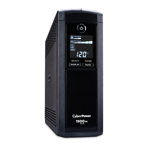
The PR500LCDRT1U/ PR750LCDRT1U/ PR1000LCDRT1U provides automatic voltage regulation for
inconsistent utility power. The PR500LCDRT1U/PR750LCDRT1U/PR1000LCDRT1U features 1030 Joules of
surge protection, and provides battery backup during power outages. The PR500LCDRT1U/ PR750LCDRT1U/
PR1000LCDRT1U ensures consistent power to your computer system and its included software will
automatically save your open files and shutdown your computer system during a utility power loss.
AUTOMATIC VOLTAGE REGULATOR(AVR)
The PR500LCDRT1U/ PR750LCDRT1U/ PR1000LCDRT1U stabilizes inconsistent utility power. The incoming
utility power may be damaging to important data and hardware, but with Automatic Voltage Regulation, the
computer will not experience damaging voltage levels. An Automatic Voltage Regulator automatically
increases low or decreases high voltage to a safe and consistent output voltage. The unit powerful sealed
lead-acid batteries will provide power only if the incoming voltage drops below 80v or increases above 150V.
SYSTEM BLOCK DIAGRAM
HARDWARE INSTALLATION GUIDE
1. Your new UPS may be used immediately upon receipt. However, recharging the battery for at least 8
hours with the unit turned on or at least 24 hours with the unit turned off is recommended to ensure that
the battery's maximum charge capacity is achieved. Charge loss may occur during shipping and storage.
To recharge the battery, simply leave the unit plugged into an AC outlet. The unit will charge in both the
on and off position.
2. If you will use the software, connect either the USB cable or Serial cable to the corresponding port on
the UPS and on the computer with PowerPanel® Business software installed. PowerPanel Business
software is available on our website. Please go to
www.cyberpowersystems.com/products/software/power-panel-business for the free download. Note:
USB and Serial port cannot be used simultaneously. Serial port will be disabled if the USB port is used.
3. With the UPS unit off and unplugged, connect your computer, monitor, and any externally powered data
storage device (Hard drive, Tape drive, etc.) into the battery power supplied outlets. DO NOT plug a
laser printer, copier, space heater, vacuum, paper shredder or other large electrical device into the UPS.
The power demands of these devices will overload and possibly damage the unit.
4. Plug the UPS into a 2 pole, 3 wire grounded receptacle (wall outlet). Make sure the wall branch outlet is
protected by a fuse or circuit breaker and does not service equipment with large electrical demands (e.g.
air conditioner, refrigerator, copier, etc.). Avoid using extension cords.
5. Depress the power switch to turn the unit on. The power on indicator light will illuminate. If an overload
is detected, an audible alarm will sound and the unit will emit one long beep. To correct this, turn the
UPS off and unplug at least one piece of equipment from the battery power supplied outlets. Wait 10
seconds. Make sure the circuit breaker is depressed and then turn the UPS on.
6. To maintain optimal battery charge, leave the UPS plugged into an AC outlet at all times.
7. To store your UPS for an extended period, cover it and store with the battery fully charged. Recharge the
battery every three months to ensure battery life.
8. EPO (Emergency Power Off) Port: The feature is for the application to enable emergency power
shutdown. Use the gray cable provided to connect the UPS to a normally closed or normally open
contact switch according to the circuit diagram. EPO function is provided in the UPS. EPO remote
switch which is a Push-Back button installed computer room outside by a phone line and not connected
any other equipment.
FRONT / REAR PANEL DESCRIPTION
1. Power Switch: Master on/off
switch for equipment connected
to the UPS.
2. Power On Indicator: Indicates the
power is on.
3. LCD Module Display: LCD shows
all the UPS information with icons
and messages.
4. LCD Display Toggle Button: The
button can be used to toggle
between different data displays
on the LCD.
5. Battery Backup and Surge Protected Outlets: Provides six battery powered, surge protected and AVR
outlets for connected equipment and ensures temporary uninterrupted operation of connected
equipment during a power failure.
Surge Only: Surge only outlet provide surge protection without backup and AVR function.
Critical /Non-critical: When the UPS is overloaded, the circuit breakers will be tripped to interrupt the
power supply to the uncritical outlets while continuing to supply the critical outlets. As well, as the
battery capacity depletes under the threshold value, the non-critical outlets will be shut down and the
UPS will provide power for critical outlets. The threshold can be determined and set by users via
software.
6. Input Power Cord: Heavy-duty, extra long power cord.
7. Input Circuit Breaker: Resettable circuit breakers provide Input optimal overload Protection.
8. USB port: USB communication port for management software.
9. Serial Port: Serial port allows connection and communication between the UPS and the computer.
10. SNMP/HTTP Network slot: Remove the cover panel to install optional RMCARD that allows remote
monitoring and control UPS on networks.
11. Site Wire Fault Indicator: This LED will illuminate to warn the user that a wiring problem exists within the
AC receptacle, such as a bad ground, missing ground or reversed wiring. If illuminated, disconnect all
equipment and contact an electrician to ensure outlet is properly wired.
12. EPO (Emergency Power Off) port: The interface can be used to connect to switches for emergency
power off.
13. TVSS Screw: To prevent the risk of electric shock, follow the steps to ground the UPS. Connect a ground
wire to the TVSS screw on the rear panel of UPS and then connect another side of the ground wire to the
ground.
Read and follow the important safety instructions before servicing the batteries. Visit CyberPower official
website www.cyberpowersystems.com or contact your dealer for more information on replacement batteries.
CAUTION! RISK OF BATTERY EXPLOSION, IF BATTERY IS REPLACED BY AN INCORRECT TYPE. DISPOSE
OF USED BATTERY ACCORDING TO THE INSTRUCTIONS.
CAUTION! RISK OF ELECTRICAL SHOCK, REFER TO INSTRUCTION MANUAL BEFORE REPLACE
BATTERY.
CAUTION! When replacing batteries, replace with the same number of the following battery: CyberPower
RB0690X2A for PR500LCDRT1U, CyberPower RB0670X4A for PR750LCDRT1U, CyberPower RB0690X4B
for PR1000LCDRT1U.
CAUTION! Risk of Energy Hazard, 6V, maximum 8 Ampere-hour battery. Before replacing batteries, remove
conductive jewelry such as chains, wrist watches, and rings. High energy through conductive materials could
cause severe burns.
CAUTION! The used batteries are considered hazardous waste and must be disposed through recycling.
Most retailers that sell lead-acid batteries collect used batteries for recycling, as required by local regulations.
Do not dispose of batteries in a fire. The batteries may explode. Follow all local ordinances regarding proper
disposal of batteries.
CAUTION! Do not open or mutilate batteries. Released material is harmful to the skin and eyes. It may be
toxic.
CAUTION! A battery can present a risk of electrical shock and high short-circuit current and. Contact with
part of a grounded battery can result in electrical shock. The following precautions should be observed when
working on batteries:
1. Remove all watches, rings or other metal objects.
2. Use tools with insulated handles.
3. Wear rubber gloves and boots.
4. Do not lay tools or metal parts on top of batteries or any terminals.
5. Remove battery grounds during installation and maintenance to reduce likelihood of shock. Remove the
connection from ground if any part of the battery is determined to be grounded.
BATTERY REPLACMENT PROCEDURE
1. Remove two screws and right
side front panel.
2. Disconnect the black and red
cable.
3. Remove two retaining screws,
pull out the old battery pack and
replace new one. Reassemble the
retaining screws, covers, black
and red cable, and front panel in
the reverse sequence of the
above steps. Recharge the unit
for at least 8 hours with the unit
turned on or at least 24 hours
with the unit turned off to ensure
maximum UPS battery runtime.
Input EMI
Filter
Surge
Suppressor AVR
Charger
AC/DC Inverter
Output
Battery
Normal Mode
Battery Mode
1
2
3
43-4 JUMPER
N.C.EPO SWITCH
OPTION 2: USER SUPPLIED NORMAL
L
Y C
L
OSE
D
S
WI
T
CH
RJ11
PLUG
1
2
3
4
NO CONNECTION
N.O.EPO SWITCH
OPTION 1: USER SUPPLIED NORMAL
L
Y OPEN
S
WI
T
CH
(RECOMMENDED)
NO CONNECTION
PRODUCT REGISTRATION
IMPORTANT SAFETY WARNINGS (SAVE THESE INSTRUCTIONS)
INSTALLING YOUR UPS SYSTEM
BASIC OPERATION
BATTERY REPLACEMENT
10
5
21
7 6
3
11
4
12 1398
1. Input Voltage Meter: This meter measures the AC voltage from
the wall outlet. The INPUT voltage readout is used to identify
the input voltage information. This can be used as a diagnostic
tool to identify the quality of input power.
2. Output Voltage Meter: This meter measures, in real time, the AC
voltage that the UPS is providing to your connected equipment
via the UPS outlets.
3. Estimated Runtime: This displays how many minutes of runtime can be expected of the UPS if it were to
experience a power outage. Note: The number displayed may be less than actual runtimes for low loads.
4. Normal Icon: This icon illuminates when the UPS is working under normal conditions.
5. Battery Icon: When there is a utility power loss, this icon will appear followed by an alarm, (two short
beeps), indicating that the UPS is now working using its internal batteries. Once the batteries are
running out of power (over a period of time), the alarm will beep rapidly every 1/2 second. If this
happens and main power has not been restored, it is recommended that you save your files and turn off
your equipment manually as soon as possible.
6. Silent Mode Icon: This icon indicates that the buzzer will not make an audible noise while in battery
operating mode. During Silent Mode, the unit’s alarm does not sound until the battery reaches
low-capacity threshold.
7. Overload Icon: This icon will appear followed by an alarm, indicating that an overload condition has been
reached. To recover from the overload condition, unplug equipment from the UPS outlets until the icon
disappears and the alarm stops.
8. LOAD CAPACITY: It is shown as a bar chart; each segment indicates approximately 25% of load capacity.
9. BATT. CAPACITY: It is shown as a bar chart; each segment indicates approximately 25% of battery
capacity.
1. GENERAL MODE
a. Press the Display Toggle button to check the UPS status:
# Items Unit
1 Input Voltage V
2 Output Voltage V
3 Load Capacity %
4 Battery Capacity %
b. Press and hold the Display toggle for 4 seconds.
-If the machine is in the Battery Mode, it enters the silent mode. Press again for 4 seconds and it
will return to normal (buzzer) mode.
-If the machine is in the Line Mode, it proceeds to Self Test.
c. If the Display toggle remains untouched for over 30 seconds, the LCD backlight will turn off
automatically.
2. SET-UP MODE
Step 1: The machine enters Set-Up Mode after holding the Display toggle for 10 seconds.
Step 2: By pressing the Display toggle, users can switch between setup functions. User configurable functions
are as follows:
a. Sensitivity: Set the level of tolerance for UPS. Increase the UPS compatibility for local utility power
condition.
-High: The UPS will turn to battery power more often to provide the steady power supply to the
connected equipment.
-Low: The UPS will tolerate more fluctuations and turn to battery power less often.
b. Battery Lifetime: Show the batteries already used time. Reset the logger when battery module
replacement or first time installation.
c. Firmware Version: Show the UPS version number.
The settable items are sorted by unit as in the following table:
# Items Unit
1 Sensitivity -
2 Battery Lifetime Year
3 Firmware Version -
Step 3: Press and hold the toggle for 4 seconds. When the icons blink, the value of each item can be changed
by slightly pressing the toggle.
Step 4: To save the value and return to general mode, press and hold the toggle for 4 seconds.
Note: If the machine is left idle for over 30 seconds during setup, it will turn off the backlight and return to
general mode automatically.
Note: If user wants to return to general mode without saving changes, there are two methods:
(1) Wait for the backlight to turn off
(2) Press and hold the Display toggle for 10 seconds
Model PR500LCDRT1U PR750LCDRT1U PR1000LCDRT1U
Capacity 500VA / 400W 750VA / 600W 1000VA / 800W
Nominal Input Voltage 125Vac
Input Frequency 60Hz +/- 3Hz (Auto-sensing)
Input Plug Type NEMA 5-15P
On Battery Output Voltage Pure Sine Wave at 120Vac +/- 5%
On Battery Output Frequency 60Hz +/- 1%
Outlets (7) NEMA 5-15R
Transfer Time (Typical) 4ms
Overload Protection On Utility: Circuit Breaker, On Battery: Internal Current Limiting
Lightning/Surge Protection Yes
Replacement Battery RB0690X2A RB0670X4A RB0690X4B
Dimensions (WxHxD) 1U Rack, 17.1” x 1.7” x
9.6” 1U Rack, 17.1” x 1.7” x 15.8”
Weight 19.8 lbs 30.7 lbs 35.9 lbs
Operating Temperature 32°F – 104°F / 0°C – 40°C
Operating Relative Humidity 0% – 95% Non-condensing
Operating Elevation 0 – 9,843 feet / 0 – 3,000 meters
Storage Temperature 5°F – 113°F / -15°C – 45°C
Storage Relative Humidity 0% – 95% Non-condensing
Storage Elevation 0 – 49,213 feet / 0 – 15,000 meters
Problem Possible Cause Solution
Outlets do not provide
power to equipment.
Circuit breaker has tripped
due to an overload.
Turn the UPS off and unplug at least one
piece of equipment. Wait 10 seconds, reset
the circuit breaker by depressing the
button, and then turn the UPS on.
Batteries are discharged. Recharge the unit for at least 4 hours.
Unit has been damaged by a
surge or spike. Contact CyberPower for repair.
Uncritical outlets have
turned off automatically
due to an overload.
Turn the UPS off and unplug at least one
piece of equipment. Wait 10 seconds, turn
the UPS on.
The UPS does not
perform expected
runtime.
Battery not fully charged. Recharge the battery by leaving the UPS
plugged in.
Battery is degraded. Contact CyberPower about replacement
batteries.
The UPS will not turn
on.
The on/off switch is designed
to prevent damage by rapidly
turning it off and on.
Turn the UPS off. Wait 10 seconds and then
turn the UPS on.
The unit is not connected to
an AC outlet.
The unit must be connected to a 120/125V
outlet.
The battery is worn out. Contact CyberPower about replacement
batteries.
Mechanical problem. Contact CyberPower for repair.
PowerPanel Business is
inactive.
The serial cable or USB cable is
not connected.
Connect the cable to the UPS unit. You
must use the cable that came with the unit.
The cable is connected to the
wrong port. Try another port of your computer.
The unit is not providing
battery power.
Shutdown your computer and turn the UPS
off. Wait 10 seconds and turn the UPS
back on. This should reset the unit.
The serial cable is not the cable
that was provided
with the unit.
You must use the cable included with the
unit for the
software
CyberPower’s patented GreenPower UPS with Bypass Technology are ENERGY STAR®
complainant ensuring lower power consumption and energy costs compared to
conventional UPS models. Even when utility power is normal, conventional UPS models
constantly pass power through a transformer. By contrast, under normal conditions the
advanced circuitry of a GreenPower UPS bypasses the transformer. As a result, the
power efficiency is significantly increased while decreasing waste heat, using less
energy, and reducing energy costs.
When an abnormal power condition occurs, the GreenPower UPS automatically runs
power through its transformer to regulate voltage and provide “safe” power. Since
utility power is normal over 88% of the time, the GreenPower UPS operates primarily in
its efficient bypass mode.
The GreenPower UPS is also manufactured in accordance with the Restriction on Hazardous Substances
(RoHS) directive making it one of the most environmentally-friendly on the market today.
The Waste Electrical and Electronic Equipment (WEEE) Directive aims to contribute to
sustainable production and consumption by contributing to the efficient use of resources and
the retrieval of secondary raw materials through re-use, recycling, and other forms of recovery.
The symbol on this product and/or its packaging indicates that the product must be disposed
of separately from ordinary household wastes at its end of life. Contact your related WEEE
management authority, local office, or your household waste disposal service about
information on the recycling drop off site.
This product contains non-spillable lead acid batteries. The used batteries are considered
hazardous waste and must be disposed through recycling. Do not dispose of used batteries
with your ordinary household wastes. Dispose of the batteries according to local
regulations.
Note: Most retailers that sell lead-acid batteries collect used batteries for recycling, as
required by local regulations.
FCC Compliance Statement This device complies with part 15 of the FCC rules. Operation is subject to the
following two conditions: (1) this device may not cause harmful interference, and (2) this device must accept
any interference received, including interference that may cause undesired operation.
Note: This equipment has been tested and found to comply with the limits for a Class A digital device,
pursuant to part 15 of the FCC Rules. These limits are designed to provide reasonable protection against
harmful interference when the equipment is operated in a commercial environment. This equipment
generates, uses, and can radiate radio frequency energy and, if not installed and used in accordance with the
instruction manual, may cause harmful interference to radio communications. Operation of this equipment in
a residential area is likely to cause harmful interference in which case the user will be required to correct the
interference at his own expense.
Important: Changes or modifications not expressly approved by the party responsible for compliance could
void the user's authority to operate the equipment.
Canadian Compliance Statement CAN ICES-3 (A)/NMB-3(A)
Please visit www.CyberPowerSystems.com for a copy of the Limited Warranty and Connected Equipment
Guarantee.
Where Can I Get More Information?
The application of the United Nations Convention of Contracts for the International Sale of Goods is expressly
excluded. CyberPower is the warrantor under Limited Warranty. For further information please feel free to
contact CyberPower at:
Cyber Power Systems (USA), Inc.
4241 12th Ave E., STE 400
Shakopee, MN 55379
Call us at (877) 297-6937; or submit a web ticket online at cyberpowersystems.com/support.
© 2023 Cyber Power Systems (USA), Inc. CyberPower®, the CyberPower logo and PowerPanel® are registered
trademarks of Cyber Power Systems (USA), Inc. All rights reserved. All other trademarks used are property of
their respective owners.
Pb Pb
DEFINITION FOR ILLUMINATED LCD INDICATORS
LCD SETUP FUNCTIONS
TECHNICAL SPECIFICATIONS
TROUBLESHOOTING
CYBERPOWER GREENPOWER UPS™ TECHNOLOGY
DISPOSAL
BATTERY DISPOSAL
REGULATORY COMPLIANCE
LIMITED WARRANTY AND CONNECTED EQUIPMENT GUARANTEE
RUN_TIMEOUTPUTINPUT
Min
V
%
LOAD BATT. CAP.
100
1
4 5
6 7
2 38 9

This manual suits for next models

3

Other CyberPower UPS manuals

CyberPower LE825DG User manual

CyberPower

CyberPower LE825DG User manual

CyberPower 649532012855 User manual

CyberPower

CyberPower 649532012855 User manual

CyberPower CyberShield CS24C12V-E User manual

CyberPower

CyberPower CyberShield CS24C12V-E User manual

CyberPower BPSE240V75ART3UOA User manual

CyberPower

CyberPower BPSE240V75ART3UOA User manual

CyberPower CP1350PFCLCD User manual

CyberPower

CyberPower CP1350PFCLCD User manual

CyberPower CPS900AVR User manual

CyberPower

CyberPower CPS900AVR User manual

CyberPower 649532004850 User manual

CyberPower

CyberPower 649532004850 User manual

CyberPower OP350TE User manual

CyberPower

CyberPower OP350TE User manual

CyberPower UT400EG User manual

CyberPower

CyberPower UT400EG User manual

CyberPower Value 600EI User manual

CyberPower

CyberPower Value 600EI User manual

CyberPower OR1000LCDRM1U User manual

CyberPower

CyberPower OR1000LCDRM1U User manual

CyberPower BU1000Ea User manual

CyberPower

CyberPower BU1000Ea User manual

CyberPower PR2000LCD User manual

CyberPower

CyberPower PR2000LCD User manual

CyberPower CP350SLG User manual

CyberPower

CyberPower CP350SLG User manual

CyberPower BR700ELCD User manual

CyberPower

CyberPower BR700ELCD User manual

CyberPower OL10000RT3UTF User manual

CyberPower

CyberPower OL10000RT3UTF User manual

CyberPower UT650E-FR/UPS User manual

CyberPower

CyberPower UT650E-FR/UPS User manual

CyberPower INTELLIGENT UPS Series User manual

CyberPower

CyberPower INTELLIGENT UPS Series User manual

CyberPower CP900AVR User manual

CyberPower

CyberPower CP900AVR User manual

CyberPower OP650 User manual

CyberPower

CyberPower OP650 User manual

CyberPower Smart App Sinewave PR2200LCD User manual

CyberPower

CyberPower Smart App Sinewave PR2200LCD User manual

CyberPower CSN75A12V3-G User manual

CyberPower

CyberPower CSN75A12V3-G User manual

CyberPower OR1500LCDRTXL2U User manual

CyberPower

CyberPower OR1500LCDRTXL2U User manual

CyberPower SMP1400EILCD User manual

CyberPower

CyberPower SMP1400EILCD User manual

Popular UPS manuals by other brands

INFOSEC E6 LCD-RT user manual

INFOSEC

INFOSEC E6 LCD-RT user manual

Liebert GHT MT+ user manual

Liebert

Liebert GHT MT+ user manual

Toshiba UC1A1A020C6TB Operation manuals

Toshiba

Toshiba UC1A1A020C6TB Operation manuals

Compaq 204451-002 - UPS T2200 XR reference guide

Compaq

Compaq 204451-002 - UPS T2200 XR reference guide

ION 30ACi Operation manual

ION

ION 30ACi Operation manual

Liebert GXT240VBATT user manual

Liebert

Liebert GXT240VBATT user manual

GE 700 VA installation guide

GE

GE 700 VA installation guide

Delta Electronics INX-1K user manual

Delta Electronics

Delta Electronics INX-1K user manual

EAST Group 9010 user manual

EAST Group

EAST Group 9010 user manual

Liebert GXT2 - 3X1 user manual

Liebert

Liebert GXT2 - 3X1 user manual

Eaton Powerware 9130 user guide

Eaton

Eaton Powerware 9130 user guide

Vertiv Liebert GXT5-6000IRT5UXLN Quick installation guide

Vertiv

Vertiv Liebert GXT5-6000IRT5UXLN Quick installation guide

Powerware Uninterruptible Power Supply Installation and operation manual

Powerware

Powerware Uninterruptible Power Supply Installation and operation manual

INFOSEC Zenergy Station 2000 user guide

INFOSEC

INFOSEC Zenergy Station 2000 user guide

Fuji Electric PEN102J1C user manual

Fuji Electric

Fuji Electric PEN102J1C user manual

GE VH Series 700 user manual

GE

GE VH Series 700 user manual

Conceptronic CUPS1200 quick guide

Conceptronic

Conceptronic CUPS1200 quick guide

Huawei UPSJZ-T Series user manual

Huawei

Huawei UPSJZ-T Series user manual

manuals.online logo
manuals.online logoBrands
  • About & Mission
  • Contact us
  • Privacy Policy
  • Terms and Conditions

Copyright 2025 Manuals.Online. All Rights Reserved.