Cyclops Lighting LEDE 300S User manual

USER MANUAL
LEDE 300-S LED
300WLED SPOT moving head performance
USER MANUAL
LEDE 300S
300 watts LED Spot moving head

Table of contents
Caution!�������������������������������������������������������������������������������������������������������������������3
Introduction ������������������������������������������������������������������������������������������������������������3
Safety instructions��������������������������������������������������������������������������������������������������3
Fxiture overview �����������������������������������������������������������������������������������������������������3
Installation ��������������������������������������������������������������������������������������������������������������4
Read ‘Safety information’ before installing the fixture��������������������������������������������������������������������������� 4
Fastening the fixture to a flat surface ���������������������������������������������������������������������������������������������������� 4
Mounting the fixture on a truss�������������������������������������������������������������������������������������������������������������� 4
Securing with a safety cable������������������������������������������������������������������������������������������������������������������ 5
DMX-512 connection/connection between fixtures ������������������������������������������������������������������������������ 5
Operation ����������������������������������������������������������������������������������������������������������������6
Addressing��������������������������������������������������������������������������������������������������������������������������������������������� 6
Universal DMX Control �������������������������������������������������������������������������������������������������������������������������� 6
RDM control������������������������������������������������������������������������������������������������������������������������������������������� 6
Stand-alone Mode ��������������������������������������������������������������������������������������������������������������������������������� 6
Master-Slave Operation������������������������������������������������������������������������������������������������������������������������� 7
Control Menu Map��������������������������������������������������������������������������������������������������7
DMX Protocol ���������������������������������������������������������������������������������������������������������8
Fixture Cleaning����������������������������������������������������������������������������������������������������11
Fuse Replacement �����������������������������������������������������������������������������������������������12
Troubleshooting����������������������������������������������������������������������������������������������������12
The fixture does not work, no light ������������������������������������������������������������������������������������������������������ 12
Specifications �������������������������������������������������������������������������������������������������������13

3Version 2.0
Caution!
• Be careful with your operations. With a dangerous voltage you can suffer a dangerous electric shock
when touching the wires!
• Avoid looking directly into the light source!
• Indoor use only, keep this device away from rain and moisture!
• Make sure it is grounded when using it!
• Unplug mains lead before opening the housing!
• For your own safety, please read this user manual carefully before you initial start-up.
• Every person involved with the installation, operation and maintenance of this device has to
- be qualified
- follow the instructions of this manual
- consider this manual to be part of the total product
- keep this manual for the entire service life of the product
- pass this manual on to every further owner or user of the product
- download the latest version of the user manual from the Internet
Introduction
Thank you for having chosen LEDE 300S. You will see you acquired a powerful and versatile device.
Unpack your item. Before you initial start-up, please make sure that there is no damage caused by
transportation. Should there be any, consult your dealer and do not use the device.
Safety instructions
This fixture is an extremely sophisticated piece of electronic equipment. To guarantee a smooth
operation, it is important to follow the guidelines in this manual. The manufacturer of this device will not
accept responsibility for damages resulting from the misuse of this fixture due to the disregard of the
information printed in this manual.
This device has left our premises in absolutely perfect condition. Always disconnect from the mains,
when the device is not in use or before cleaning it. Keep away children and amateurs from the device!
There are no serviceable parts inside the device. Maintenance and service operations are only to be
carried out by authorized dealers.
Fxiture overview
e
1
2
3
4
5
6
781091112
1Head
2Yoke
3Tilt lock
4Pan lock
5Carrying handl
6Base
7Up button
8Enter button
9Menu button
10
11 Touch screen
12 5V micro USB
(set DMX address)
Down button

4Version 2.0
13 14 15 16 17
13
14
15
16
17
3-pin DMX input socket
3-pin DMX output socket
Powercon in
Fuse
The head should be locked for transportation- the tilt lock latch (3) and the pan lock latch (4) have to be in the locked
positions. To unlock the head, move these latches to unlock positions before operating the fixture.
5V micro USB port enable user to adjust fixtures' DMX address without connecting to the main power. The screen
will be lit up when connected to the power bank(and not connected to main power).
Installation
Read ‘Safety information’ before installing the xture
The fixture is designed for indoor use only and must be used in a dry location with adequate ventilation. Ensure that
none of the fixture’s ventilation slots are blocked.
Fasten the fixture to a secure structure or surface. Do not stand it on a surface or leave it where it can be moved
or fall over. If you install the fixture in a location where it may cause injury or damage if it falls, secure it as directed
in this user manual using a securely anchored safety cable that will hold the fixture if the primary fastening method
fails.
Fastening the xture to a at surface
The fixture can be fastened to a hard, fixed, flat surface that is oriented at any angle. Ensure that the
surface and all fasteners used can support at least 10 times the weight of all fixtures and equipment to
be installed on it.
Fasten the fixture securely. Do not stand it on a surface or leave it where it can be moved or fall over.
If you install the fixture in a location where it may cause injury or damage if it falls, secure it as directed
below with a securely anchored safety cable that will hold the fixture if the primary fastening method fails.
Mounting the xture on a truss
The fixture can be clamped to a truss or similar rigging structure in any orientation. When installing the
fixture hanging vertically down, you can use an open-type clamp such as a G-clamp. When installing in
any other orientation, you must use a half-coupler clamp that completely encircles the truss chord.
To clamp the fixture to a truss:
1. Check that the rigging structure can support at least 10 times the weight of all fixtures and equipment
to be installed on it.
2. Block access under the work area.
3. Fold the legs of the mounting bracket together and bolt a rigging clamp securely to the mounting
bracket. The bolt used must be M12. It must pass through both mounting bracket legs and be

5Version 2.0
fastened with a self-locking nut.
4. Working from a stable platform, hang the fixture with its clamp on the truss and fasten the clamp
securely.
5. Secure the fixture with a safety cable as directed below.
Securing with a safety cable
Secure the fixture with a safety cable (or other secondary attachment) that is approved for the weight of
the fixture so that the safety cable will hold the fixture if a primary attachment fails.
Loop the safety cable through the eyebolt in the back of the fixture and around a secure anchoring point.
Do not loop the safety cable around the fixture’s mounting bracket only, as this will leave the fixture
unsecured if it separates from the bracket.
DMX-512 connection/connection between xtures
Occupation of the XLR-connection:
1. Group
2. Signal (-)
3. Signal (+)
DMX OUT
1. Group
2. Signal (-)
3. Signal (+)
DMX IN
If you are using controllers with this occupation, you can connect the DMX-output of the controller directly
with the DMX-input of the first fixture in the DMX-chain. If you wish to connect DMX-controllers with other
XLR-outputs, you need to use adapter-cables.
Building a serial DMX-chain:
Connect the DMX-output of the first fixture in the DMX-chain with the DMX-input of the next fixture.
Always connect one output with the input of the next fixture until all fixtures are connected.
DMX-512 connection with DMX terminator:
For installations where the DMX cable has to run a long distance or is in an electrically noisy
environment, such as in a discotheque, it is recommended to use a DMX terminator. This helps in
preventing corruption of the digital control signal by electrical noise. The DMX terminator is simply an
XLR plug with a 120 resistor connected between pins 2 and 3, which is then plugged into the output XLR
socket of the last fixture in the chain.
Caution: At the last fixture, the DMX-cable has to be terminated with a terminator. Solder a 120
resistor between Signal (–) and Signal (+) into a 3-pin XLR-plug and plug it in the DMX-output of the
last fixture.
Connection with the mains:
The LEDE 300S is equipped with auto-switching power supply that automatically adjusts to any 50-60Hz
AC power source from 100-240 Volts.
This fixture must be earthed. To use the fixture, a plug must be fixed.
The correct assembly of a sufficient plug may be done by professional persons only.
The conductors in the cable are marked by the following table.
Connect the device to the mains with the enclosed power supply cable.

6Version 2.0
Operation
The LEDE 300S can operate in three different modes. In each mode you can run the fixture as a
stand alone fixture or in a master/slave confiugration. This next section will detail the dif-ferences in the
operating modes.
Addressing
All fixtures should be given a DMX starting address when using a DMX signal, so that the correct fixture
responds to the correct control signals. This digital starting address is the channel number from which
the fixture starts to listen to the digital control information sent out from the DMX controller. The allocation
of this starting address is achieved by setting the correct number on the display located on the base of
the device.
You can set the same starting address for all fixtures or a group of fixtures, or make different address for
each fixture individually.
If you set the same address, all the units will start to listen to the same control signal from the same
channel number. In other words, changing the settings of one channel will affect all the fixtures
simultaneously.
If you set a different address, each unit will start to listen to the channel number you have set, based on
the quantity of control channels of the unit. That means changing the settings of one channel will affect
only the selected fixture.
In the case of the LEDE 300S, which is 20/25 channels fixture. If you set, for example, the address in
the 20 channel mode to channel 21, the device will use the channel 21 to 41 for control.
Universal DMX Control
This function allows you to use a universal DMX-512 controller to control the chases and patterns,
dimmer and strobe. A DMX controller allows you to create unique programs tailored to your individual
needs.
RDM control
The LEDE 300S RDM can communicate using RDM (Remote Device Management) in accordance with
ESTA’s American National Standard E1.20-2006: Entertainment Technology RDM Remote Device Man-
agement Over DMX512 Networks.
RDM is a bi-directional communications protocol for use in DMX512 control systems, it is the open stan-
dard for DMX512 device conguration and status monitoring.
The RDM protocol allows data packets to be inserted into a DMX512 data stream without affecting ex-
isting non-RDM equipment. It allows a console or dedicated RDM controller to send commands to and
receive messages from specic xtures.
With RDM function, you can set the DMX address of your fixtures remotely. This is especially useful
when the device is installed in a remote area.
Each LEDE 300S has a factory set RDM UID (unique identication number).
Stand-alone Mode
In this mode, you can run internal program without a controller.
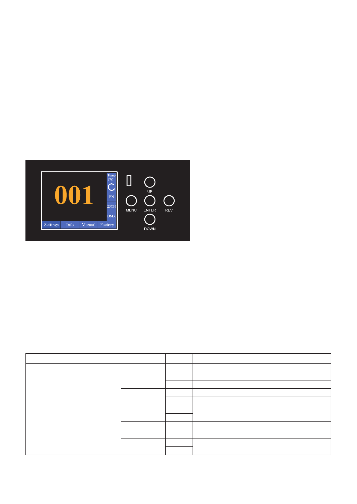
1. Press the Setting icon in in the touch screen.

7Version 2.0
2. Select the Fixture Set tab.
3. Press Up or Down button and select Run Mode and select Host.
4. The fixture will run internal programs.
Master-Slave Operation
This function will allow you to link up to 16 units together and operate without a controller. In a Master-
Slave set up one unit will act as the controlling unit and the others will react to the controlling units
programs. Any unit can act as a Master or as a Slave.
1. Using approved DMX data cables, daisy chain your units together via the XLR connector on the rear
of the units.
2. For the Master unit press the Setting - Fixture set - Run Mode - Host icon in in the touch screen.
3. For the slave units press the DMX address icon in the touch screen. Set the DMX address to 001.
4. The slave units will now follow the Master unit.
Control Menu Map
The control panel on the front of the fixture,
provides access to the system menu and is
where all necessary system adjustments are
made to the fixture. LCD touch screen makes
it very easy to navigate the system menus.
During normal operation, pressing MENU
button once will access the fixture’s main
menu.
Once in the main menu you can navigate through the different functions and access the sub-menus with
the UP, DOWN, and ENTER buttons.
Once you reach a field that requires adjusting, press the ENTER button to activate that field and use
the UP and DOWN buttons to adjust the field. Pressing the ENTER button once more will confirm your
setting.
You may exit the main menu at any time without making any adjustments by pressing the MENU button.
The REV button makes it quick reverse of the LCD display.
Default settings=bold print
Main Menu Level 1 Level 2 Level 3 Function
Setting
DMX address 001-512 DMX address setting
Fixture set
DMX Mode STD Channel mode, standard - 25CH
BAC Channel mode, simplified - 20CH
Run Mode DMX Control mode, DMX
Host Control mode, Auto program
Pan Inverse Close Pan reverse movement
Open
Tilt Inverse Close Tilt reverse movement
Open
Quiet Mode Close Theater mode (Fan mode)
Open

8Version 2.0
Display
Language EN Language, English
Display Flip Close Display Reverse 180°
Open
Display Mode Show Display blacklight, always on
60S Display blacklight, 60 seconds
Reset
XY Reset Cancel Pan Tilt reset
Run
Moto Reset Cancel Motos reset
Run
All reset Cancel Reset all
Run
Factory Cancel Factory default
Run
Info
Time
Current Time
System time
Show Time
Power Time
Sensor Sensor
Software Version
Panel
Software versionMoto-XY
Moto
Manual
Pan 000 - 255
Manual control on board
Pan Fine 000 - 255
Tilt 000 - 255
...
Zoom 000 - 255
Zoom Fine 000 - 255
Factory
Password xxx
Advanced settings/calibration(Only
qualified technicians should perform
this function. Inqure your local
dealer for password.)
Pan
Input correct password for calibration
Tilt
Iris
Color
Rot Gobo
Gobo Rot
Fix Gobo
Frost
Color 7
Effect
Prism
Prism Rot
Zoom
Focus
DMX Protocol
MODE/CHANNEL DMX value Function
STD 25 BAC 20
1 1 Pan
000-255 Pan movement by 540°
2 2 Pan ne
000-255 Fine control of pan movement

9Version 2.0
3 3 Tilt
000-255 Tilt movement by 270°
4 4 Tilt fine
000-255 Fine control of tilt movement
5 5 Pan/Tilt speed
000-255 Pan/Tilt speed, decreasing
6 6
Marco Function
000-129 No function
130-150 Pan/Tilt reset
151-159 No function
160-180 Effect reset
181-189 No function
190-210 All reset
211-255 No function
7 7
Strobe
000-009 Closed
010-120 Strobe slow to fast
121-129 Open
130-180 Pulse strobe fast to slow
181-189 Open
190-240 Pulse strobe slow to fast
241-249 Random strobe slow to fast
250-255 Open
8 8 Dimmer
0-255 0-100 linear dimmer
9 9
Color wheel
0-9 Open/hole
10-19 Color 1 (Color1+white)
20-29 Color 2 (Color1)
30-39 Color 3 (Color1+color2)
40-49 Color 4 (Color2)
50-59 Color 5 (Color3+color3)
60-69 Color 6 (Color3)
70-79 Color 7 (Color3+color4)
80-89 Color 8 (Color4)
90-99 Color 9 (Color4+color5)
100-109 Color 10 (Color5)
110-119 Color 11 (Color5+color6)
120-129 Color 12 (Color6)
130-139 Color 13 (Color6+color7)
140-149 Color 14 (Color7)
150-159 Color 15 (Color7+white)
160-169 Open/hole
170-255 Forward rainbow effect from slow to fast
10 * Color wheel ne
0-255 Color wheel fine
11 10
Gobo Wheel 1(Fixed gobo)
000-009 Open/hole
010-019 Gobo 1
020-029 Gobo 2
030-039 Gobo 3
040-049 Gobo 4
050-059 Gobo 5
060-069 Gobo 6

10 Version 2.0
070-079 Gobo 7
080-089 Gobo 8
090-112 Backwards rotation from fast to slow
113-120 Stop
121-143 Forwards rotation from slow to fast
Shaking gobos from slow to fast
144-157 Gobo 1
158-171 Gobo 2
172-185 Gobo 3
186-199 Gobo 4
200-213 Gobo 5
214-227 Gobo 6
228-241 Gobo 7
242-255 Gobo 8
12 11
Animation effect wheel
000-004 Open/hole
005-027 Gobo 1
028-034 Gobo 1~2
035-056 Gobo 2
057-063 Gobo 2~3
064-084 Gobo 3
085-089 Open
090-119 Gobo 1 rotation
120-149 Gobo 2 rotation
150-179 Gobo 3 rotation
180-214 Backwards rotation fast to slow
215-220 Open
221-255 Forwards rotation slow to fast
13 12
Gobo Wheel 2(Rotating gobo wheel)
000-009 Open/hole
010-019 Gobo 1
020-029 Gobo 2
030-039 Gobo 3
040-049 Gobo 4
050-059 Gobo 5
060-069 Gobo 6
700-079 Gobo 7
080-0129 Backwards rotation from fast to slow
130-135 Stop
136-185 Forwards rotation from slow to fast
Shaking gobos from slow to fast
186-195 Gobo 1
196-205 Gobo 2
206-215 Gobo 3
216-225 Gobo 4
226-235 Gobo 5
236-245 Gobo 6
246-255 Gobo 7

11 Version 2.0
14 13
Rot. gobo indexing and rotation
Gobo indexing
0-63 Gobo indexing
64-126 Forwards rotation from fast to slow
127-128 Stop
129-191 Backwards rotation from slow to fast
192-193 Stop
194-255 Forwards and backwards rotation from slow to fast
15 * Rot. gobo - ne
0-255 Fine indexing (rotation)
16 14
Prism
0-127 Open position (hole)
128-255 3 facet prism
17 15
Prism rotation and indexing
000-127 Prism indexing
128-190 Backwards rotation from fast to slow
191-192 Stop
193-255 Forwards rotation from slow to fast
18 * Prism Rotation Fine
0-255 Prism Rotation Fine
19 16
Iris
0-134 Linear
135-164 Fast open, Slow close
165-194 Slow open, Fast close
195-224 Normal Rain Effect
225-255 Random Rain Effect
20 17
Frost
0-127 Open/hole
128-255 Frost
21 18 0-255 6 colors color wheel
22 19 Focus
0-255 Continuous adjustment from far to near
23 * Focus ne
0-255 Fine focusing
24 20 0-255 Zoom
25 * Zoom ne
0-255 Fine zooming
Fixture Cleaning
Due to fog residue, smoke, and dust cleaning the internal and external optical lenses and mirror should
be carried out periodically to optimize light output. Cleaning frequency depends on the environment
in which the fixture operates (I.e. smoke, fog residue, dust, dew). In heavy club use we recommend
cleaning on a monthly basis. Periodic cleaning will ensure longevity, and crisp output.
To clean the fixture:
1. Disconnect the fixture from power and allow it to cool for at least 10 minutes.
2. Vacuum or gently blow away dust and loose particles from the outside of the fixture with low-pressure
compressed air.
3. Clean the surfaces by wiping gently with a soft, clean lint-free cloth moistened with a weak detergent
solution. Do not rub glass surfaces hard: lift particles off with a soft repeated press. Dry with a soft,
clean, lint-free cloth or low-pressure compressed air. Remove stuck particles with an unscented
tissue or cotton swab moistened with glass cleaner or distilled water.
4. Check that the fixture is dry before reapplying power.

12 Version 2.0
Fuse Replacement
This fuse is located in a fuseholder next to the MAINS OUT socket on the connections panel.
To replace a fuse:
1. Disconnect the fixture from power and allow it to cool for at least 10 minutes.
2. Unscrew the cap of the fuseholder and remove the fuse. Replace with a fuse of the same size and
rating only.
3. Reinstall the fuseholder cap before reapplying power.
Troubleshooting
Listed below are a few common problems that you may encounter, with solutions.
The xture does not work, no light
• Check the connection of power and main fuse. Be sure the external fuse has not blown.
• Measure the mains voltage on the main connector.
•

13 Version 2.0
www.cyclopslighting.com
DMX connections: 3 pin XLR In/Out male and female
Power connections: PowerCon In
Dimensions: 369 x 292 x 599mm
Net weight: 18�6 Kg
Housing: Plastic
Color: Black
IP rating: 20
Specications
Model LEDE 300S
Light source: 300 watts white LED
LED life expectancy: 50,000 Hrs�
Color temperature: 6600K
CRI 70
Beam angle: 13° to 44°
Light output: 60,000 Lux @ 2m @ 13°
Electronic focus
Dimmer: Linear adjustment
Color wheel: 7 colors + open
Effect color wheel: 6 colors
Electronic variable strobe
Static gobo: 8 gobos +open
Rotating gobo: 7 gobos + open
Gobo shake function
Animation wheel: continuous bi-directional rotation animation wheel
Prism: 3-facet circular prism
Iris
Frost filter
Control protocols: DMX, Auto Run, Master-Slave
Control channels: 20, 25 CHs
Pan: 540°
Tilt: 270°
Resolution: 16 bit
Input voltage: 100-240V/50-60Hz
Power consumption: 300 watts
Table of contents
Other Cyclops Lighting Light Fixture manuals
Popular Light Fixture manuals by other brands

NOMA
NOMA Canvas CTI1510721 instruction manual

Cooper Lighting
Cooper Lighting EIVM Series Specifications

Philips
Philips Guardsman Vandal Resistant specification

RSA Lighting
RSA Lighting Combolight Galleria Series PAR38 120V specification

Lightolier
Lightolier Lytecaster 1100DAICM specification

Stoane Lighting
Stoane Lighting Module M Installation and maintenance instructions