Cygnus 850 Instruction Manual

Page 1 of 6
CYGNUS 850 2 Mbps MODEM
Quick Start Installation Guide
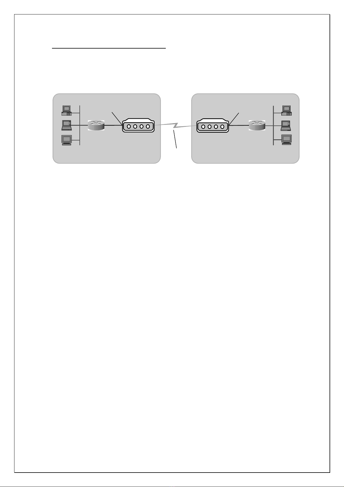
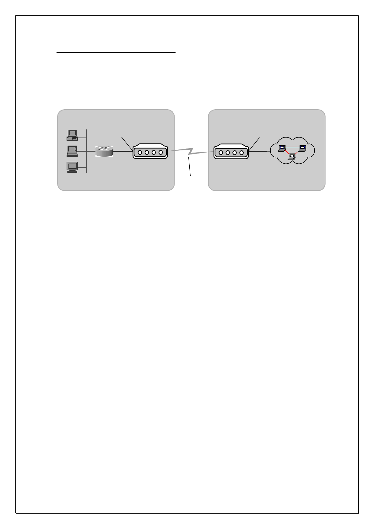
Before installing the modem, verify the leased line is of 2 Mbps ( Unframed ) or Nx64 kbps ( Framed ). If it is
unframed 2 Mbps then you can directly connect the E1 and V.35 modem in the line as CYGNUS 850 modem
factory default configuration is unframed 2 Mbps. Both end ( Premises & Local Exchange ) modems should
have same configuration either framed or unframed but not different configuration.
For configuring CYGNUS 850 modems, connect the PC Comm. port to the console port ( 9 pin Female )
of the modem which is provided on the front panel.
The PC Comm. port parameters should be as follows :
Speed -9600 bps
Databits –8
Parity -None
Stopbit -1
Flowcontrol –None
When you access the supervisory functions through the console port, it is password protected and menu
driven. The default password for logging in is the character “0”. When you log into the supervisory you
reach its “Root ” menu.
1. Unframed configuration ( 2 Mbps )
To configure the modems for unframed -2 Mbps speed ( factory default ), navigate through the menus to
configure factory default parameters ( 2.1.9 of flowchart diagram ) and type “Y” to load the factory
default parameters.
When system prompts to ignore password, press enter and navigate through the menus to store the
parameters in NVRAM ( 2.1.7 of flowchart diagram ) and type “Y” to save the parameters. Restart the
system manually by switching it OFF & ON or go to reset the unit ( 2.1.8 of flowchart diagram ) and type
“Y” to reset the system through software.
Verify the same by entering into the menus and select to view the unit status ( 1.0 of flowchart
diagram ). Verify the Framing parameter, it should be Unframed.
Both the units ( V.35 & E1 ) should have same configuration i.e. Unframed.
2. Framed ( for 64 kbps, 128 kbps, 256 kbps, 512 kbps & 1 Mbps )
If we need to configure the modems for other than 2 Mbps speeds ( eg.: 128 kbps ), follow the below
procedure.
To configure the modem for n x64 kbps speed, you need to configure the framing type to framed and the
number of timeslots ( eg.: for 128 kbps, slot 1 & 2 ) as DTE for V.35 and E1 for E1 modem.
To configure framing type, navigate through the menus to configure Framing Type ( 2.1.2 of flowchart
diagram )and select as Framed.
To configure timeslots, navigate through the menus to configure TDM timeslots ( 2.2 of flowchart
diagram ). Each slot is of 64 kbps.
If your speed is 1984 kbps ( i.e. 31 x 64 kbps ),select to configure all timeslots as DTE in V.35 modem
and to configure all timeslots as E1 ( 2.2.2 of flowchart diagram ) in E1 modem.

Page 2 of 6
If your speed is multiples of 64 kbps ( eg.: 128 kbps i.e. 2 slots ), then select to configure individual
timeslots ( 2.2.3 of flowchart diagram ) and you will get a prompt to enter the timeslot. Start with “1”,
select it as DTE for V.35 modem & as E1 for E1 modem and continue upto the number of timeslots you
required as per the speed ( for 128 kbps only 1 & 2 slots should be DTE/E1 and remaining slots should be
IDLE ). For 256 kbps speed 4 slots and for 512 kbps 8 slots should be DTE/E1 keeping all other slots as
IDLE.
All the changes done in the configuration will take effect only after the same has been saved and the unit
is restarted.
To save the parameters, navigate through the menus to store parameters in NVRAM (2.1.7 of
flowchart diagram ) and type “ Y” to save.
Then you can restart the unit manually or by selecting to reset the unit ( 2.1.8 of flowchart diagram ) from
the system parameters menu and typing “ Y”.
To see the configuration, select to view unit status and check Framing, it should be Framed for V.35
modem and Framed:PCM31 for E1 modem.
Both the units ( V.35 & E1 ) should have same configuration i.e. framed.
After following the above steps for configuring, the modem is ready to be connected on line.

Page 3 of 6
Menus flow chart of CYGNUS 850 E1 Modem
Root
1.To view unit status 3.For control function2.To configure the unit
To view unit running
parameters
2.To configure TDM
timeslots
For diagnostics tests &
to view line Statistics
1.To configure system
parameters
3.To configure DSL
port parameters
4.To configure E1 port
parameters
1.To configure System
Cloc ing mode
5.To specify unit ID
1.To set this to NO
2.To set this to YES
4.To configure Rate vs Range
trade off
1.To set to 2E11-1
2.To set to 2E15-1
3.To configure Test Pattern
Type
1.To set to unframed 2Mbps
2.To set to framed nX64 bps
2.To configure Framing
Type
1. Line Slave 2. E1 Sla e
3. Internal
To configure unit ID
6.To specify console port
password
To configure Console
password
7.To store parameters in
NVRAM
To save the parameters
8.To reset the unit
To reset the unit
9.To configure factory
default parameters
To load the factory default
parameters
1.To configure DSL Type
2.To configure DSL Frame
Type
1.DSL Type as LT
2.DSL Type as NT
1.Frame Type as Sync
2.Frame Type as Plesio
1.To configure all timeslots
as IDLE
2.To configure all timeslots
as E1
3.To configure individual
timeslots
1.To configure E1 Port line
interface
2.To configure E1 Port
Framing Type
1.To set this to 75 Ohm
2.To set this to 120 Ohm
1.PCM30 2.PCM30C
3.PCM31 4.PCM31C
3.To configure PCM30
CAS ABCD signaling
4.To configure PCM30
CAS ABCD idle signaling
5.To configure Console
Port parameters
1.To configure Console
Port speed
2.To configure Console
Port parity
1.4800 bps 2.9600 bps
3.19200 bps 4.38400 bps
5.57600 bps
1.Even 2.Odd 3.None
3.To configure Console
Port Databits
4.To configure Console
Port Stopbits
1.To set this to 7 bit
2.To set this to 8 bit
1.To set this to 1 bit
2.To set this to 2 bit
Factory default parameters
System Cloc : E1 Slave
DSL Type : LT
Framing : Unframed

Page 4 of 6
Menus flow chart of CYGNUS 850 V.35 Modem
Factory default parameters
System Cloc : Line Slave
DSL Type : NT
Framing : Unframed
Root
1.To view unit status 3.For control function2.To configure the unit
To view unit running
parameters
2.To configure TDM
timeslots
For diagnostics tests &
to view line Statistics
1.To configure system
parameters
3.To configure DSL
port parameters
4.To configure DTE
port parameters
1.To configure System
Cloc ing mode
5.To specify unit ID
1.To set this to NO
2.To set this to YES
4.To configure Rate vs Range
trade off
1.To set to 2E11-1
2.To set to 2E15-1
3.To configure Test Pattern
Type
1.To set to unframed 2Mbps
2.To set to framed nX64 bps
2.To configure Framing
Type
1. Line Sla e 2. DTE Slave
3. DTE XTX 4. Internal
To configure unit ID
6.To specify console port
password
To configure Console
password
7.To store parameters in
NVRAM
To save the parameters
8.To reset the unit
To reset the unit
9.To configure factory
default parameters
To load the factory default
parameters
1.To configure DSL Type
2.To configure DSL Frame
Type
1.DSL Type as LT
2.DSL Type as NT
1.Frame Type as Sync
2.Frame Type as Plesio
1.To configure RX Cloc
inversion
2.To configure TX Cloc
inversion
1.No inversion of RX Cloc
2.Invert Rx Cloc
1.No inversion of TX Cloc
2.Invert TX Cloc
3.To configure Data
inversion
1.No data inversion
2.Data invert
1.To configure all timeslots
as IDLE
2.To configure all timeslots
as DTE
3.To configure individual
timeslots
5.To configure Console
Port parameters
1.To configure Console
Port speed
2.To configure Console
Port parity
1.4800 bps 2.9600 bps
3.19200 bps 4.38400 bps
5.57600 bps
1.Even 2.Odd 3.None
3.To configure Console
Port Databits
4.To configure Console
Port Stopbits
1.To set this to 7 bit
2.To set this to 8 bit
1.To set this to 1 bit
2.To set this to 2 bit

Page 5 of 6
Configuration for 2 V.35 modems connectivity
1. When two V.35 modems are used in the circuit to connect two premises, then one V.35 modem should be
configured as LT with Internal clock mode and the other modem should be in factory default mode.
2. The diagram shows the connectivity of two V.35 modems.
Connectivity using two V.35 Modems
`
CYGNUS 850/V.35
modem
CYGNUS 850/V.35
modem
2-wire Line
Router
LAN LAN
V.35 interface
Router
Location A Location B
V.35 interface
3. To change the clocking mode, navigate through the menus to configure System Clocking mode ( 2.1.1 of
flowchart diagram ) and select change option. Then select internal clock mode.
4. To change the DSL type,navigatethrough the menus to configure DSL Type ( 2.3.1 of flowchart diagram )
and then select DSL Type as LT.
5. After performing the above steps, save the parameters by navigating through the menus to store
parameters in NVRAM ( 2.1.7 of flowchart diagram ).
6. Then restart the modem manually and verify the parameters by navigating through the menu to view unit
status.In that Clocking should be Internal and DSL Type should be LT.
7. Now the modems are ready to be connected in the line.

Page 6 of 6
Configuration for 2 E1 modems connectivity
1. When two E1 modems are used in the circuit to connect local exchange and the customer premises, then
one E1 modem should be configured as NT with Line Slave clock mode to connect at the customer
premises and the other modem should be in factory default mode to be connected at local exchange.
2. The diagram shows the connectivity of two E1 modems.
Connectivity using two E1 Modems
`
CYGNUS 850/E1
modem
CYGNUS 850/E1
modem
2-wire Line
LAN
E1 interface
Router
Premises Exchange
E1 interface
PCM
3. To change the clocking mode, navigate through the menus to configure System Clocking mode ( 2.1.1 of
flowchart diagram ) and select change option. Then select Line Salve clock mode.
4. To change the DSL type, navigate through the menus to configure DSL Type ( 2.3.1 of flowchart diagram )
and then select DSL Type as NT.
5. Before installing the modems, verify the leased line is of 2 Mbps ( Unframed ) or Nx64 kbps ( Framed ). If it
is unframed 2 Mbps then you can directly connect the E1 modems in the line as default speed is 2 Mbps. If
we need to configure the modems for other than 2 Mbps speeds ( eg.: 128 kbps ), refer page 1 for the
configuration.
6. After performing the above steps, save the parameters by navigating through the menus to store
parameters in NVRAM ( 2.1.7 of flowchart diagram ).
7. Then restart the modem manually and verify the parameters by navigating through the menu to view unit
status. In that Clocking should be Internal and DSL Type should be LT.
8. Now the modems are ready to be connected in the line.
This manual suits for next models
2