Cyron PRO HD HTW1012 User manual

1

2
CHATSWORTH,CAUSA www.cyron.com
PRO HD IR Controller
HTW1012
Thank you for purchasing CYRON HTW1012 Media Highlighter IR controller.
Please follow all the steps to assure proper installation and optimum usage of
this device. Read through the instructions before you start your project.
Contents _____
Locate all system components. If
any of the components are
missing or damaged contact
CYRON before proceeding with
installation.
1 X Controller
1 X Remote control
1 X IR receiver
1 X Audio headphone cord
4 X Mounting screws
Possibilities _____
HTW1012 is compatible with all CYRON multicolor/RGB lights. Controller is
provided with 12 ports for easy connections to Media Highlighter Lightbars.
For the ultimate expandability, the system is also equipped with internal
terminal blocks that allow hardwiring the system without the use of ports. By
hardwiring, the system will be able to handle much larger lighting systems. See
Table for details.
Hardwiring needs ample knowledge of wiring practices and should be done by
experienced professionals such as electricians or certified custom electronic
installers. Please contact CYRON Technical Support for further details.
Installations _____
CONTROLLER should preferably be installed out of sight, while planning for
the IR receiver to be installed in line of sight. REMOTE needs to be pointed at
the IR receiver for operation. Cautions and Common practices:

3
Keep the controller and wires away from extreme heat, liquids, and moving
objects.
Low voltage wires can be routed through walls and cabinets as long as proper
care is taken to avoid damages.
DO NOT modify internal components. Tampering with components and wiring
may cause severe damage to your system and will void factory warranty.
The CONTROLLER operates on 100% regulated 12 or 24VDCpower. The
size (wattage) of the power supply depends on the number of lights. Table
below will help in determining the maximum number of lights and the power
supply ratings to be used.
CYRON
Series/Size
Watts per
one lightbar
Model no.
available (Qty)
Max Qty
with
HTW1012
HTP (Pro) / 9”
1.20
HTPB9 (2x9”)
160
HTP (Pro) / 15”
2.20
HTPB15 (2x15”)
90
HTP (Pro) / 24”
4.00
HTPB24 (2x24”)
50
Ribbon LED /HTPR
2.20 / ft
HTPR-RL
90 feet
Ribbon LED / HTPRX
2.20 / ft
HTPRX-RL
90feet
HTPRZ-2H24
4.40 / ft
HTPRZ-2H24RL
90 feet
There are two methods of connecting lights to the controller:
1. PLUG-n-PLAY lightbar connection
CYRON Media Highlighter multicolor lights are supplied with pre-installed
connectors which can be directly plugged into controller ports. Pay attention to
the polarity of the plugs. Donot use excessive force. The order in which they
get connected does not matter. You can plug as few as one or as many as
twelve. Use wire zip ties or other means of wire management to secure the
wires.
CYRON hub extender (part# HTH61) provides 5 more outlets. If your system
is using too many hub extenders, then you should be thinking about hardwiring
the lights instead.
2. HARDWIRING Connecting more than 12 CYRON lightbars
You may choose this option if :
a) You are connecting far more than 12 lightbars
b) Lightbar wires are too short for your project
c) Using CYRON Ribbon lights
d) You are a contractor and are familiar with wiring practices
e) Intending to utilize more than 100 watts of power

4
Hardwiring needs ample knowledge of wiring practices. This option should be
done by experienced professionals such as electricians or certified custom
electronic installers. Please contact CYRON Technical Support for further
details. There may be other options available for your project. CYRON
experienced Tech Support staff will be happy to help you implement your
project.
See Appendix A for detailed hardwiring instructions.
Operations _____
The HTW1012 remote is designed to be quite intuitive. However, it has
many featureswhich may take sometime to get familiar with. Please
take sometime to learn all the features.
Power, Turn on
Power, Turn off
Pre-programmed Light show: Sequentially displays seven
preset colors (colors cannot bechanged).
Pre-programmed Light show: Color Transition. Smooth color
transition of lights thru a
preset color pallet.
Pre-programmed Light
show: aka Breath mode.
Sequentially fadesin and
fadesout seven preset
colors (colors cannot be
changed).
Slow speed (60 seconds)
Medium speed (5 sec)
Fast speed (1 sec)
Dimming buttons do not operate in
Light shows
Stops the light show on
the color displayed at that
instance.

5
Turn-off timer. There are5 timers of 1, 2, 3, 4 and 5 hours.
Each time the button is pressed the lights will flash according
to thenumberof hours.
>First press; lights flashonce; system turns off in 1 hour.
>Second press; lights flash twice; system turns off in 2 hours.
>Third press; lights flash three times; system turns off in 3
hours.
Sameapplies for up to 5 hours. Press again to go back to 1
hour.
Red, Green and Blue COLOR DIALS allow adjustment of
each color from zero brightness to full brightness in very finite
steps. The number of steps (modulation resolutions) is
explained on Page 7 in Hi Def Modulation section. The UP
arrows increase and down arrows decreasethe brightness level
of each particular color. By combining different levels of each
color morethan 500,000 color and brightness combinations
will be possible. Use COLOR DIALS to match décorcolors,
create varies tones of white light, or reduce thebrightness of
colors. See Memory function below to save a custom color.
COLOR DIALS only operate on memorized colors and
PAUSED colors.
You cannot press-and-hold to rapidly change thru the
steps. Buttons must be pressed once for each step.
MUSIC MODE. The lights will changecolors and interact
with sound. There are two ways to take advantageof this
feature.
a. Built in Microphone: A microphoneis placed
inside the controller which can pick up ambient
sound. If theambient sound is loud enough thelights
will start to interact. Placement of the controller box
and theamplitudeof sound playsa big role in how
well the Music Light will work.
b. Audio Input: Alternatively, you may plug the
headphone output of a stereo system or personal
music player to the MIC input. A cord hasbeen
provided. Depending on youraudio system you may
need a different type of connection.The built-in
microphoneis disable once the cord hasbeen
plugged into the controller.

6
aDO NOT connect audio input to speakeroutputs.
Controller will be damaged.
Sound sensitivity can be adjusted by pressing the MUSIC
button morethanonce,up to 5 times. Every time thebutton is
pressed there will be a sequence of light flashes, from one
flash to 5 flashes. 5 flashesindicates the sound sensitivity is at
its minimum.Depending on the type of sound/music and the
audio output level, the sensitivity adjustment may not play a
big role in light interaction. Experiment with different typesof
music and output levels to get the optimum Music Light
appearance.
For more audio control look for CYRON inline adjustable
attenuatorand Y-splitter at www.CYRON.com.
Instant white light. Preset cool white. Custom white tones can
be programmed.See Page 7 Custom White Settings.
Other tonesof white can be achieved using COLOR DIALS.
In general, lowering the green and blue will generate
“warmer” tones of white.
Memory buttons1 thru 7 can beused to memorize colors. To
memorize a color press the and then press the desired
memory button 1 thru 7. Lights will flash confirming the
process.
Dimming buttons allow you to dim any “memorized” or
“pa used” light in 4 steps of 100%, 75%, 50% and 25%.
Dimming does not work for light shows.
Dimming works best for memory buttons1-7 or the
instant white light.
Dimming levels lower than 25% can be achieved by
first memorizing a color at 25% level. Then recalling
the color and dimming it again will result in lower
levels. Repeatingthis process can result in dimming
levels near 1%.

7
Auto Turn ON/Off _____
HTW1012 can be set to automatically turn on every time the power has
been disconnected and then restored. This is referred to asAuto On
mode.Inversely, it can be set to never turn on automatically when the
power is restored, alsoreferred to asAuto Off.
Use Auto On setting and connect the controller to a timer.
Every time the timer comes on the lights will turn on
automatically.Same is true if controller is plugged into an
outlet that is controlled by a wall switch. Lights can be turned
on by the wall switch
To set the controller to Auto On:
Turn off the lights using the power off button.On the remote press
buttons"7, 7, 1". Lights will flash to confirm. Disconnect power and
reconnect to test. Lights should turn on automatically.
To set the controller to Auto Off:
Turn off the lights using the power off button.On the remote press
buttons"7, 7, 2". Lights will flash to confirm. Disconnect power and
reconnect to test. Lights should remain off.
Hi Definition Modulation
HTW1012 can operate at 3 different modulation rates. Lower
modulations ratesmake it easier to navigate through the color dial
buttonsbut may show flickering effect when viewed with 3D glasses or
shooting digital video. Table below shows options:
PW Modulation
Rate
Color Dial
Steps
Setting: Button
sequence
Standard
51
OFF, 5, 5, 1
High Def
127
OFF, 5, 5, 2
Super High Def
255
OFF, 5, 5, 3
Custom White Settings
White button is preprogrammed at 100% white which is combination of
red, green and blue all at max levels. Results is a high color
temperature tone of white light almost resembling a light blue. The
exact color dependson the lighting element used. Other tonesof white
can be produced by reducing blue and green channels. As it would with
any othercolor, this "custom white" color can also be programmed in
any of the seven memory buttons. Alternatively it can be saved in the

8
WHITE button instead.Once the desired toneof white hasbeen
reached press MEM 6 times and then press WHITE.
General Guidance _____
How to make a specific color:
It is best to start from a solid color that is close to the color you are trying to
get. Forexample if you are trying to produce a specific shade of sea green it is
best to start with solid green and using COLOR DIALS add blue until the
desired color is reached. To recall it in the future save in memory.
How to produce a color when watching a color show:
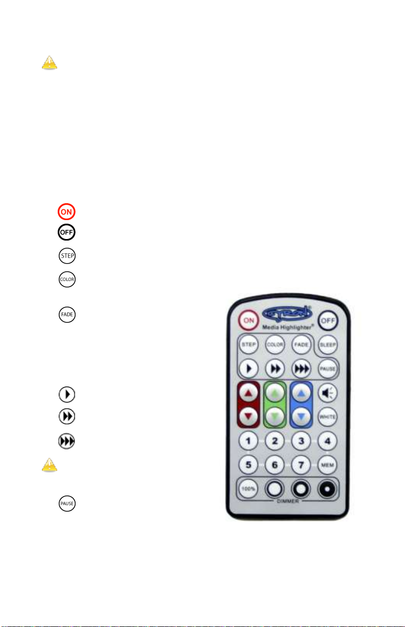
While watching any of the color shows you can press PAUSEbutton to freeze
the show on the color being displayed. A quick way to get to some of the solid
colors maybe to PAUSEthe lights in the STEP mode.
Different tones of white light:
White light is presence of all primary colors. Otherwise, red green and blue
mixed together will make white light. However, what most traditional lights
produce is far from a “white” light. Depending on the type of light it could have
a yellowish tone, bluish tone, or green tone. Most people think of white light as
yellowish white aka “warm white”. A color similar to “warm white” can be
nearly replicated using the HTW1012 controller. The WHITE button produces
a 100% red/green/blue combination. Depending on the type of CYRON lights
you use, this may produce a shade of white that needs further adjustment.
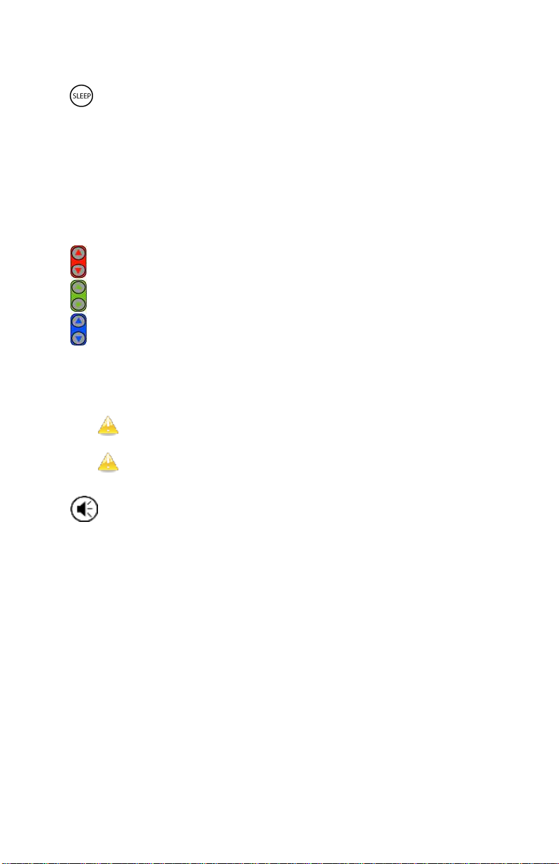
Generally, reducing green and blue using COLOR DIALSwill produce a
warmer shade of white, while reducing red will create a cooler white. Play
around with COLORDIALS and keep an open mind in what you may have
known as “white”.
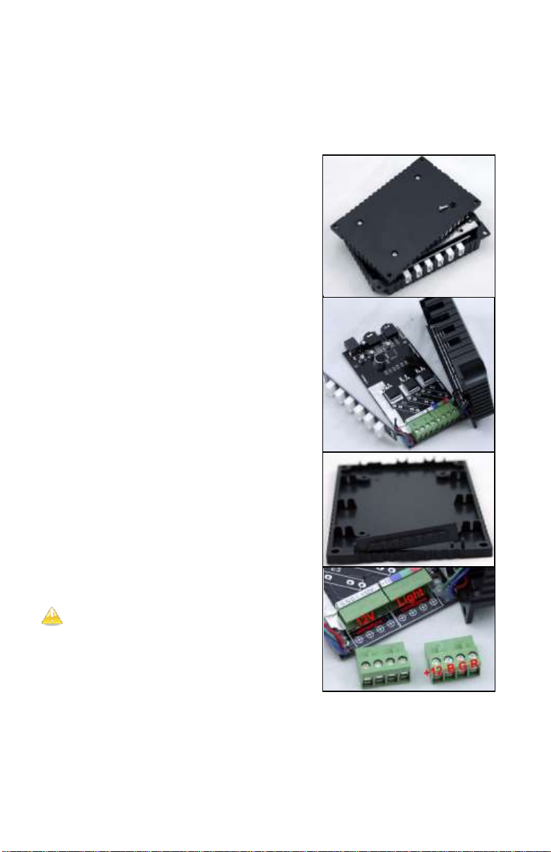
Can I use the portsand the internal terminal block at the sametime?
Yes, lights can be connected to terminal block and the external ports. However,
the power supply connection is best to be at either terminal blocks or external
DC jack, not both simultaneously. CAUTION:Do not exceed the max rating of
DC jack.
Specifications _____
Supply voltage range 9-24VDC
Supply current 6A max via DC jack
18A max via terminal block, 14AWG x 4
Continuous output power 200W @ 12VDC, 400W @ 24VDC
Peak output power 400W
Working Temperature -20 to 60ºC
Common terminal Anode
Standby power 0.5W
Audio line input 0.5V, 100Ω
Dimensions 5" x 3 3/8"x 1" (128mm x 85mm x 25mm)
Remote, battery CR2025, 3V

9
_______________________
___ Appendix A ___
_______________________
Hardwire Instructions _____
STEP ONE: Open the HTW1000 controller box
by removing four screws on the bottom.
STEP TWO: Gently take out one of the side
circuit boards holding the 6 ports. Lift the main
PCB to gain access to the terminal blocks. Be
careful not to break any wires connecting the
boards.
STEP THREE: Take out the housing wire cap.
STEP FOUR: Connect wires to the hub
following the color code shownin Table One.
Use minimum 18AWGx4 (4 conductor 18
gauge) wire for extending lightbar wires up to
100ft. For runs over 100ft you must increase
the wire gauge accordingly.
Do not connect too many wires directly to the
terminal block. To minimize wire clutter
connect one or two main leads to the terminal
block. Then by means of standard electrical
connections the main lead can be connected to
however many lights may be needed.
Note that 12VDC and lightbars wires can all be connected to the hub.
Connecting the 12VDCdirectly to the hub is required for power supplies over
60watts. Four terminal inlets have been provided for 12V positive and negative.
For power sources over 100W it is a good idea to use four wires, two for the

10
positive, two for the negative. This will eliminate extra current being carried
over one wire.
Wire Color Code
HTW1012
Terminal Block
HTHUB6Wires
CYRON Ribbonlights
Marking/ Wire
+12V
White
+12, 24 / Com / Black
B
Black
B / Blue
G
Green
G / Green
R
Red
R / Red
STEP FIVE: Place the PCBs back in their positions and close the back cover.
Pay close attention to the wires connecting the side PCBs to the main PCB.
STEP SIX: Manage the wires. Use zip ties or other
means to secure the wires together. As stated in the
User Manual, the IR receiver will need to be connected
to the IR plug. The IR receiver needs to be in the line of
sight in order for the remote to work.
Keep the controller and wires away from
extreme heat, liquids, and moving objects.
Low voltage wires can be routed through
walls and cabinets as long as proper care is
taken to avoid damages.
DO NOT modify internal components.
Tampering with components and wiring will
void factory warranty.

11
Technical Support _____
CYRON’s goal is 100% customer satisfaction. You may call our technical
support line or contact us via email 24/7.
techsupport@cyron.com
818-772-1900 x106
To continually improve our products we welcome all comments about the
product you purchased.
Thank You!
Warranty _____
Cyron warrants this product against any defects in materials or workmanship for a period of ONE (1) year from the
date of purchase. The warranty covers normal usage as intended by the factory and does not cover misuse, abuse,
accidents, or damages caused due to the acts of God. Proof of purchase is required.
ANY IMPLIED WARRANTIES, INCLUDING WITHOUT LIMITATION THE IMPLIED WARRANTIES OF
MERCHANTABILITY AND FITNESS FOR A PARTICULAR PURPOSE, SHALL BE LIMITED TO THE
DURATION OF THIS LIMITED WARRANTY, OTHERWISE THE REPAIR, REPLACEMENT, OR REFUND AS
PROVIDED UNDER THIS EXPRESS LIMITED WARRANTY IS THE EXCLUSIVE REMEDY OF THE
CONSUMER, AND IS PROVIDED IN LIEU OF ALL OTHER WARRANTIES, EXPRESS OF IMPLIED. IN NO
EVENT SHALL CYRON, INC. BE LIABLE, WHETHER IN CONTRACT OR TORT (INCLUDING
NEGLIGENCE) FOR DAMAGES IN EXCESS OF THE PURCHASE PRICE OF THE PRODUCT, ACCESSORY
OR FOR ANY INDIRECT, INCIDENTAL, SPECIAL OR CONSEQUENTIAL DAMAGES OF ANY KIND, OR
LOSS OF REVENUE OR PROFITS, LOSS OF BUSINESS, OR OTHER FINANCIAL LOSS ARISING OUT OF OR
IN CONNECTION WITH THE ABILITY OR INABILITY TO USE THE PRODUCTSOR ACCESSORIES TO THE
FULL EXTENT THESE DAMAGES MAY BE DISCLAIMED BY LAW.
Some states and jurisdictions do not allow the limitation or exclusion of incidental or consequential damages, or
limitation on the length of an implied warranty, so the above limitations or exclusions may not apply to you. This
warranty gives you specific legal rights, and you may also have other rights that vary from state to stateor from one
jurisdiction to another.
Further warrantyinquiries: warranty@cyron.com

12
Warranty Registration
To take advantage of all warranty benefits and futureproduct
enhancements pleaseregister your product at link below
https://www.cyron.com/productregistration.aspx
2017 CYRON, Inc., All rights reserved
Table of contents
Popular Controllers manuals by other brands

Mitsubishi Electric
Mitsubishi Electric AnyWire ASLINK user manual

Doli
Doli EDC 60 Assembly instructions

DOGA
DOGA BM Series instruction manual

Daikin
Daikin homecontrols EKRUFHT61V3 Installation and operation manual

Skipala
Skipala DIGR-1502/E user manual

Distech Controls
Distech Controls EC-NPB-2X-485 Hardware installation guide