Cytron Technologies Shield-PS2 User manual

ROBOT.HEADtoTOE
ProductUser’sManual–ShieldPS2
Index
1. IntroductionandOverview 3
2. PackingList 4
3. ProductSpecificationandLimitations 5
4. BoardandProductLayout 6
5. HardwareInterface 8
5.1ChooseSONYPS2DualShockController 10
6. Protocol 15
6.1PS2Buttonandjoystickstatus 15
6.2OnBoardvibratormotorcontrol 16
6.3AllPS2buttonandjoystickstatus 17
7. Warranty 19
CreatedbyCytronTechnologiesSdn.Bhd.–AllRightsReserved 2

ROBOT.HEADtoTOE
ProductUser’sManual–ShieldPS2
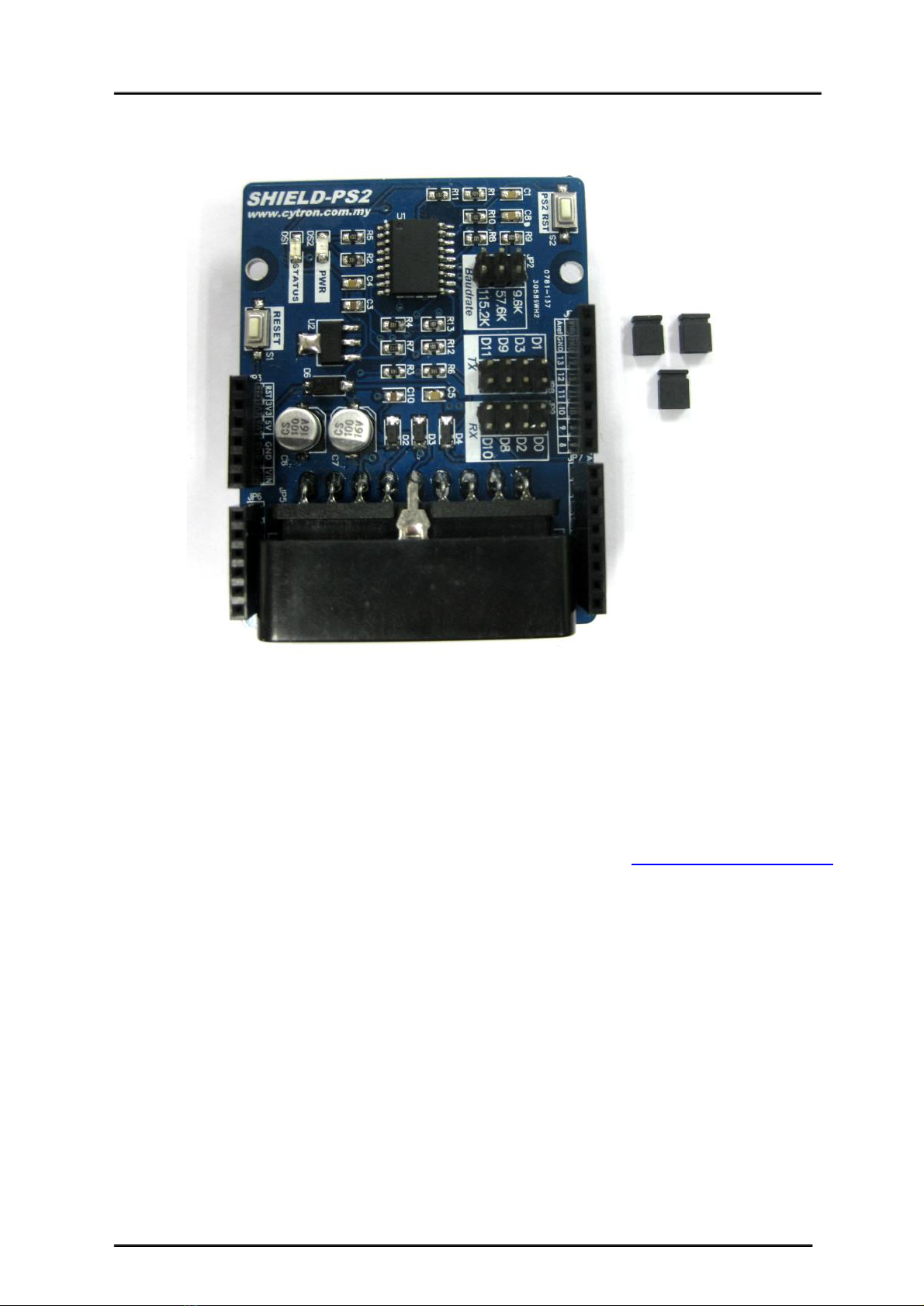
1.0INTRODUCTIONANDOVERVIEW
Cytron PS2 Shield (SHIELDPS2) is an Arduino compatible shield which is compatible with
Arduino UNO, Arduino Duemilanove, Arduino Mega, Arduino Leonardo and possibly other pin
compatible main boards. Cytron PS2 Shield offers a compact yet reliable PS2 Controller
Converter for user. Cytron PS2 Shield is powered from Arduino main board. with Cytron PS2
Shield Reading Joystick and button’s state of PS2 controller will be as easy as reading UART data.
ItoffersastandardconnectorforSONYPS2controllertoplugin,eitherwiredorwireless.
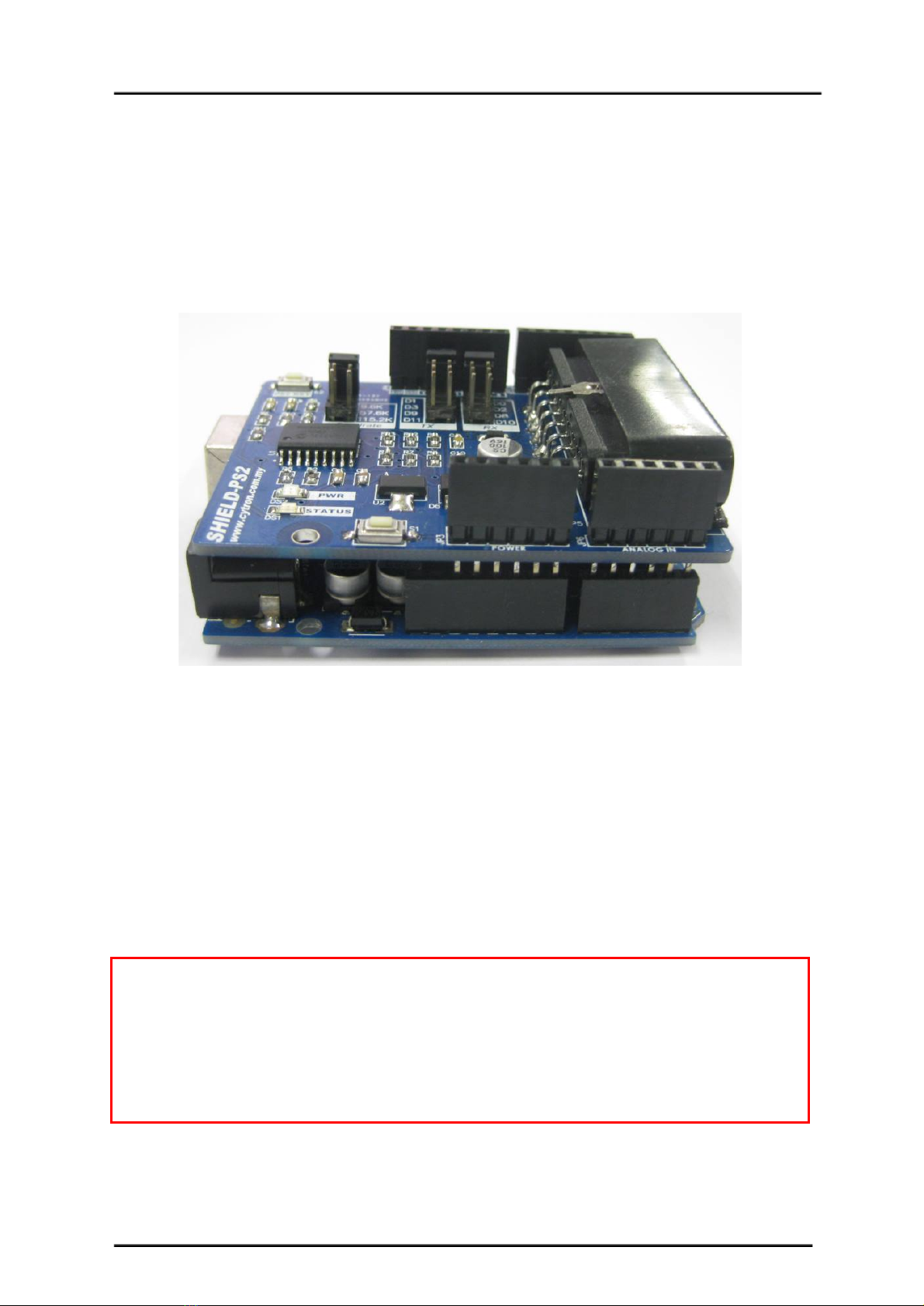
ShieldPS2 has stackable side headers which allows for more Arduino shields to be stacked on top
of it. Besides, user has option to use either hardware or software UART with Arduino’s main
board to communication to get the PS2 controller status. ShieldPS2 reset is connect to arduino’s
analogpin1(A1).Usercanpulldownthisanalogpintoresettheshield.
Features:
● 5Vpowered,lowcurrentconsumption.
● SimpletouseUARTprotocol
● VibratormotoronPS2iscontrollable.
● WiredandWirelessPS2controllerissupported.
● PS2Controllerwillautomaticallyoperateinanalogmode.
● AstatusLED
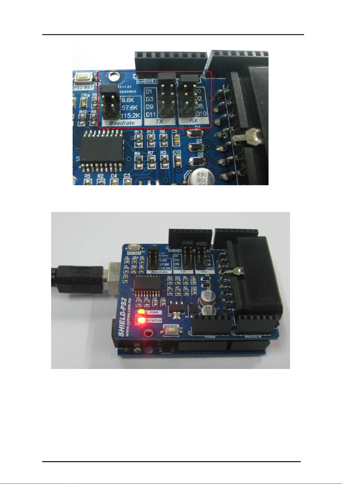
● JumperselectortoselectdifferentUARTBaudRate(4800,9600,57600,115200).
● JumperselectorstoselectdifferentdigitalpinasUARTTXandRXpin.
CreatedbyCytronTechnologiesSdn.Bhd.–AllRightsReserved 3

ROBOT.HEADtoTOE
ProductUser’sManual–ShieldPS2
2.0PACKINGLIST
1. 1xShieldPS2
2. 3xminijumper
3. User’smanual,andsamplesourcecodecanbedownloadedfromhttp://www.cytron.com.my.
CreatedbyCytronTechnologiesSdn.Bhd.–AllRightsReserved 4

ROBOT.HEADtoTOE
ProductUser’sManual–ShieldPS2
3.0PRODUCTSPECIFICATIONANDLIMITATIONS
Dimensions
No
Parameters
Min
Typical
Max
Unit
1
InputVoltage(LogicOperationVoltage)
4.5
5.5
V
2
CurrentConsumption
100
150
500
mA
3
VIOH(LogicInput–HighLevel)
3.5
5.0
5.5
V
4
VIOL(LogicInput–LowLevel)
0
0
1.0
V
CreatedbyCytronTechnologiesSdn.Bhd.–AllRightsReserved 5

ROBOT.HEADtoTOE
ProductUser’sManual–ShieldPS2
4.0PRODUCTLAYOUT
ComponentsonShieldPS2andtheirfunctions:
1. StackableAnalogInputHeader
This is the analog port of the Arduino. The stackable header allows other stacked shield to
utilizethesepins.
2. StackablePowerPinsHeader
This is the power port of the Arduino. The stackable header allows other stacked shield to
utilizethesepins.
3. MainBoardresetbutton
CreatedbyCytronTechnologiesSdn.Bhd.–AllRightsReserved 6

ROBOT.HEADtoTOE
ProductUser’sManual–ShieldPS2
Arduinomainboardwillrequirearound30mstoreadyafterreset.
4. StatusindicatorLED(Orange)
ThisLEDwillblinkandilluminatewithdifferentbrightnessdependingonthePS2status.
LEDCondition
Description
Blinkwithdifferent
brightness
Once power up, if there is no SONY PS2 controller connected or
detected..
Stayilluminatedwith
lowbrightness
SONYPS2controllerdetectedandcommunicationisworkingfine.
Stayilluminatedwith
highbrightness
DigitalbuttononSONYPS2controllerispressed.
5. PowerindicatorLED(Green)
IndicatortoshowsthatpowerissuppliedtoCytronPS2Shield.
6. BaudRateselector
To select the preferable UART baud rate For Cytron PS2 Shield to obtain latest baudrate
fromselector,ShieldPS2needtoberesettoupdatetheboard’sbaudrate.
7. OnboardCytronPS2Shieldresetbutton
PS2RSTbuttonwillonlyresettheSHIELDPS2butnottheArduinoMainboard.
8. StackableDigitalI/OHeaders
JP4andJP7areDigitalI/OpinsstackedtotheArduinomainboard.
9. RXPinSelector
UsermayselectD0,D2,D8orD10asRXpinforSHIELDPS2withtheminijumper.
10. TXPinSelector
UsermayselectD1,D3,D9orD11asTXpinforSHIELDPS2withtheminijumper.
11. SONYPS2ConnectorSocket
PleaseconnectPS2Controllerplughere,wirelessorwired.
CreatedbyCytronTechnologiesSdn.Bhd.–AllRightsReserved 7

ROBOT.HEADtoTOE
ProductUser’sManual–ShieldPS2
5.0HARDWAREINTERFACE
This section shows the example of using SHIELDPS2 with Arduino UNO as the main controller.
However, other Arduino main board such as Arduino Duemilanove and Arduino Mega can also be
used.
Figure below shows that the SHIELDPS2 is stacked on the Arduino UNO. Please ensure that the
pinsalignmentiscorrect.
Select the pins for UART’s TX and RX. Pin D0 and D1 are hardware serial of most arduino main
board. Other selectable pin for TX and RX on ShieldPS2 are software serial pin. The default TX
pin is set to D3 while the RX pin is set to D2. However, other pins may be selected if these pins are
already used by other application. If hardware serial pin (D0, D1) is selected, user needs to unplug
the PS2 Connector from the ShieldPS2 before start to program the main board. Programming of
main board may fail if the ShieldPS2 is stacked on mainboard and PS2 controller connector is
connected.SelectdesiredbaudrateforShieldPS2usingtheminijumper.
Guidelinetochoosepinforsoftwareserial:
Not all pins on the Mega and Mega 2560 support change interrupts,
so only the following can be used for RX:
10, 11, 12, 13, 50, 51, 52, 53, 62, 63, 64, 65, 66, 67, 68, 69
Not all pins on the Leonardo support change interrupts,
so only the following can be used for RX:
8, 9, 10, 11, 14 (MISO), 15 (SCK), 16 (MOSI).
CreatedbyCytronTechnologiesSdn.Bhd.–AllRightsReserved 8

ROBOT.HEADtoTOE
ProductUser’sManual–ShieldPS2
USB cable to Arduino main board and load example code. Sample source code and Arduino’s
LibrarycanbedownloadedfromtheSHIELDPS2productpageatCytron’swebsite.
Connect the PS2 joystick to the PS2 connector socket on SHIELDPS2 as shown. Don’t forget
about the power source for the Arduino main board too. Power source for the Arduino main board
isfromDCadaptorplug.
CreatedbyCytronTechnologiesSdn.Bhd.–AllRightsReserved 9

ROBOT.HEADtoTOE
ProductUser’sManual–ShieldPS2
5.1ChooseSONYPS2DualShockController
User are free to choose any type of SONY PS2 controller in the market, either wired or wireless.
Figure below shows example of wired and wireless type of SONY PS2 controller. There are many
types of PS controller in the market and the sensitivity for each type also different. User is advised to
use original PS2 controller. Cytron Technologies does not guarantee compatibility for all PS2
controllers.NomodificationisneededtoconnecttoSKPS.
WiredSONYPS2Controller
WirelessSONYPS2Controller
CreatedbyCytronTechnologiesSdn.Bhd.–AllRightsReserved 11

ROBOT.HEADtoTOE
ProductUser’sManual–ShieldPS2
FigurebelowshowsthedigitalbuttonsandanalogjoystickonatypicalPS2controller.
The analog value of Left Joystick and Right Joystick can be read from SKPS too. Each joystick
have 2 axes, and there are two formats of output. These formats will be explained later. User may
chooseformat1orformat2.
NOTE:
SONY PS2 controller does not come with PS2 Shield, please purchase separately from Cytron
Technologies website. It is advised to use PS2 controller from Cytron Technologies because
PS2controlleristestedbeforeitisbeingshippedtocustomer.
CreatedbyCytronTechnologiesSdn.Bhd.–AllRightsReserved 12

ROBOT.HEADtoTOE
ProductUser’sManual–ShieldPS2
Analogoutputformat1:
There are 2 variables for each joystick, axis X and axis Y, this is what we commonly use in graph
drawing. On PS2 joystick, as example, when user push the joystick up or down, the Y axis will
change.Meanwhileifuserpushthejoystickleftorright,thevalueofXaxiswillchange.
YAxis:
● Middle(neutral),valueis128
● Pushup,valuechangefrom128to0
● Pushdown,valuechangefrom128to255.
XAxis:
● Middle(neutral,valueis128
● Pushtowardsleft,valuechangefrom128to0
● Pushtowardsright,valuechangefrom128to255
LeftjoystickhaveXaxisandYaxis,RightjoystickalsohaveitsownXandYaxis.
AnalogvalueofFormat1
Takinganexample,let’ssaytheleftjoystickisbeingpushtothepositionshowninthefigure.Itis
beingpushtolefttopcorner.Thevalueofleftjoystickwillchangewillshouldgetapproximately:
● j_lx=70
● j_ly=92
Thisisjustanexample,wenoticealotofPS2joystickdonotprovidelinearanalogvalueacrossthe
range.Thereisabigdeadzonenearthemiddlepositionwhereanalogvaluedoesnotchange.User
isrequireto“play”aroundwiththejoystick.
CreatedbyCytronTechnologiesSdn.Bhd.–AllRightsReserved 13

ROBOT.HEADtoTOE
ProductUser’sManual–ShieldPS2
Analogoutputformat2:
In format 2, there are four variables for each joystick. The four variables are up, down, left and
right. When user move the joystick in any direction, the value of these four variables change from 0
to100.LeftandRightjoystickwillhave4independentvariables.
AnalogvalueofFormat2
Takinganexample,let’ssaytheleftjoystickisbeingpushtothepositionshowninthefigure.Itis
beingpushtoleftdowncorner.Thevalueofleftjoystickwillchangewillshouldgetapproximately:
● j_ll=10
● j_ld=50
YoucanchoosewhicheverformattousebysendingparticularcommandtoPS2Shield.
Pleasedotakenotethatthetheformat1variablesare:
● j_lxLeftjoystick,Xaxis
● j_lyLeftjoystick,Yaxis
● j_rxRightjoystick,Xaxis
● j_ryRightjoystick,Yaxis
Format2variablesare:
● j_luLeftjoystick,upaxis
● j_ldLeftjoystick,downaxis
● j_llLeftjoystick,leftaxis
● j_lrLeftjoystick,rightaxis
● j_ruRightjoystick,upaxis
● j_rdRightjoystick,downaxis
● j_rlRightjoystick,leftaxis
● j_rrRightjoystick,rightaxis
CreatedbyCytronTechnologiesSdn.Bhd.–AllRightsReserved 14

ROBOT.HEADtoTOE
ProductUser’sManual–ShieldPS2
lmeanLeftjoystick
rmeanRightjoystick
xmeanXaxis,format1,range0to255
ymeanYaxis,format1,range0to255
umeanUpaxis,format2,range0to100
dmeanDownaxis,format2,range0to100
lmeanLeftaxis,format2,range0to100
rmeanRightaxis,format2,range0to100
CreatedbyCytronTechnologiesSdn.Bhd.–AllRightsReserved 15

ROBOT.HEADtoTOE
ProductUser’sManual–ShieldPS2
6.PROTOCOL
By default, ShieldPS2 is in passive condition, where it waits for command from UART. If Arduino
main board sends a command, it will response based on the command and the status of PS2 button
and joystick. The command is simple, it is in value. Each value will request ShieldPS2 to check the
particularbuttonorjoystickstatusonPS2andresponse.
6.1PS2ButtonandJoystickStatus
Send
(decimal)
ButtononPS2
Description
0
1
2
3
4
5
6
7
8
9
10
11
12
13
14
15
Selectbutton
leftjoystickcentrebutton
rightjoystickcentrebutton
STARTbutton
upbutton
rightbutton
downbutton
leftbutton
L2button
R2button
L1button
R1button
trianglebutton
circlebutton
crossbutton
squarebutton
Appliedtovalue0to15(decimal):
ShieldPS2willreturnthestatusofcorresponding
buttonwhentheparticulardecimalvalueis
received
0ifthebuttonispressed
1ifbuttonisnotpressed
Example:
Ifmainboardsent10(decimal),ShieldPS2will
checkL1buttonstatusonPS2Controller.
ShieldPS2willreturn:
0ifL1buttonispressedor
1ifL1isnotpressed.
16
17
18
19
20
leftjoystickxaxis
leftjoystickyaxis
rightjoystickxaxis
rightjoystickyaxis
leftjoystickupvalue
CreatedbyCytronTechnologiesSdn.Bhd.–AllRightsReserved 16

ROBOT.HEADtoTOE
ProductUser’sManual–ShieldPS2
21
22
23
24
25
26
27
leftjoystickdownvalue
leftjoystickleftvalue
leftjoystickrightvalue
rightjoystickupvalue
rightjoystickdownvalue
rightjoystickleftvalue
rightjoystickrightvalue
Appliedtovaluefrom16to27(decimal):
ShieldPS2willreturntheparticularvalueof
correspondingjoystickintheselectedaxis
Example:
Ifmainboardsent20(decimal),ShieldPS2will
readandreturnthevalueofleftjoystickup.
28
Returntheconnectionstatus
ofPS2controlleron
ShieldPS2
ShieldPS2willreadPS2controllerstatus
1isreturnifcontrollerisdetectedorconnectedto
thePS2connectoronShieldPS2
6.2OnboardVibratorMotorControl
Following commands require two bytes of data send from main board. 1st byte to indicates which
vibratormotor,followingbyte(2ndbyte)toindicatormotorstatusorthespeed.
send1stbyte
(decimal)
send2ndbyte
(decimal)
Controller
Description
29
motor1value
smallervibratoronright
motor1=1(motoron)
motor1=0(motoroff)
30
motor2value
biggervibratoronleft
motor2=0to255
(adjustablespeed)
CreatedbyCytronTechnologiesSdn.Bhd.–AllRightsReserved 17

ROBOT.HEADtoTOE
ProductUser’sManual–ShieldPS2
6.3AllPS2ButtonandJoystickStatus
Send(decimal)
ResponsefromPS2
Description
31
6bytesofdata:
1stbyte:digitalbuttongroup1
2ndbyte:digitalbuttongroup2
3rdbyte:RightJoystickXaxis
4thbyte:RightJoystickYaxis
5thbyte:LeftJoystickXaxis
6thbyte:LeftJoystickYaxis
ShieldPS2willreturnthestatusofall
digitalandanalogjoystickofPS2
Digitalgroup1:
bit7(MSB):Leftbutton
bit6:Downbutton
bit5:Rightbutton
bit4:Upbutton
bit3:Startbutton
bit2:RightJoystickCenterbutton
bit1:LeftJoystickCenterbutton
bit0(LSB):Selectbutton
Digitalgroup2:
bit7(MSB):Squarebutton
bit6:Crossbutton
bit5:Circlebutton
bit4:Trianglebutton
bit3:R1button
bit2:L1button
bit1:R2button
bit0(LSB):L2button
0ifthebuttonispressed
1ifbuttonisnotpressed
Example:
Ifmicrocontrollersent31(decimal),
ShieldPS2willcheckallthebuttonand
joystickstatusandreturn6bytesto
microcontroller.
CreatedbyCytronTechnologiesSdn.Bhd.–AllRightsReserved 18

ROBOT.HEADtoTOE
ProductUser’sManual–ShieldPS2
Examples:
ExampleofUARTcommunicationshowsmainboardobtaintheCirclebuttonofPS2
ExampleofUARTcommunicationshowsmainboardobtaintheLeftjostick,XaxisvalueofPS2
CreatedbyCytronTechnologiesSdn.Bhd.–AllRightsReserved 19

ROBOT.HEADtoTOE
ProductUser’sManual–ShieldPS2
7.0WARRANTY
● Productwarrantyisvalidfor12months.
● Warrantyonlyappliestomanufacturingdefect.
● Damagedcausedbymisuseisnotcoveredunderwarranty
● Warrantydoesnotcoverfreightcostforbothways.
Preparedby
CytronTechnologiesSdn.Bhd.
19,JalanKebudayaan1A,
TamanUniversiti,
81300Skudai,
Johor,Malaysia.
Tel: +6075213178
Fax: +6075211861
URL: www.cytron.com.my
Email: [email protected]
CreatedbyCytronTechnologiesSdn.Bhd.–AllRightsReserved 20
Other manuals for Shield-PS2
1
Table of contents
Other Cytron Technologies Carrier Board manuals