Cytron Technologies Shield-PS2 User manual

ROBOT . HEAD to TOE
Product User’s Manual – Shield-PS2
Index
1. Introduction and Overview 3
2. Packing List 4
3. Product Specification and Limitations 5
4. Board and Product Layout 6
5. Hardware Interface 8
5.1 Choose PS2 Dual Shock Controller 10
6. Protocol 15
6.1 PS2 Button and joystick status 15
6.2 On Board vibrator motor control 16
6.3 All PS2 button and joystick status 17
7. Warranty 19
Created by Cytron Technologies Sdn. Bhd. – All Rights Reserved 2

ROBOT . HEAD to TOE
Product User’s Manual – Shield-PS2
1.0 INTRODUCTION AND OVERVIEW
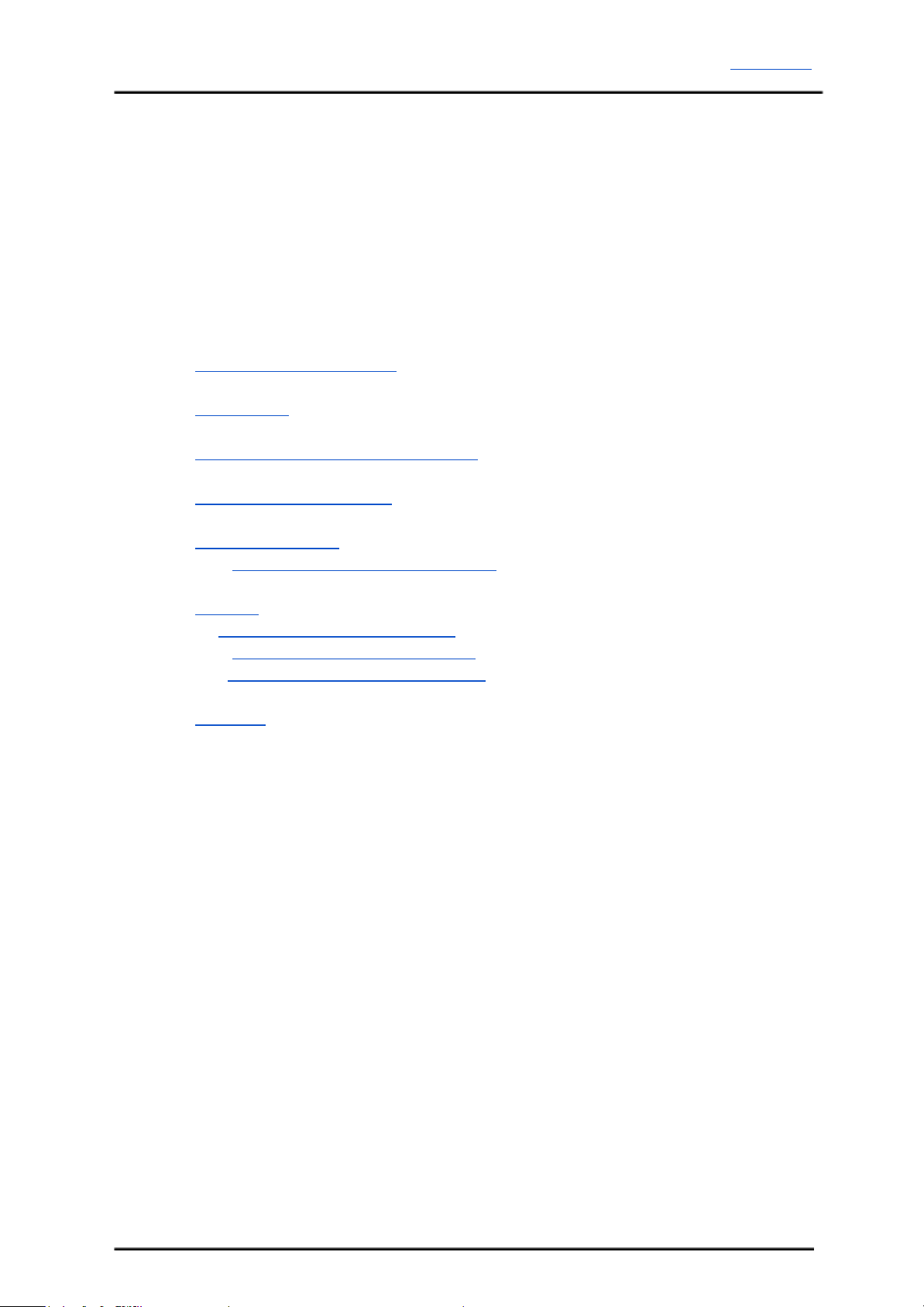
Cytron PS2 Shield (SHIELD-PS2) is an Arduino compatible shield which is compatible with
Arduino UNO,Arduino Duemilanove,Arduino Mega, Arduino Leonardo and possibly other
pin compatible main boards. Cytron PS2 Shield offers a compact yet reliable PS2 Controller
Converter for user. Cytron PS2 Shield is powered from Arduino main board. with Cytron PS2
Shield Reading Joy-stick and button’s state of PS2 controller will be as easy as reading
UART data. It offers a standard connector for SONY PS2 controller to plug-in, either wired
or wireless.
Shield-PS2 has stackable side headers which allows for more Arduino shields to be stacked
on top of it. Besides, user has option to use either hardware or software UART with
Arduino’s main board to communication to get the PS2 controller status. Shield-PS2 reset is
connected to arduino’s analog pin 1 (A1). User can pull down this analog pin to reset the
shield.
Features:
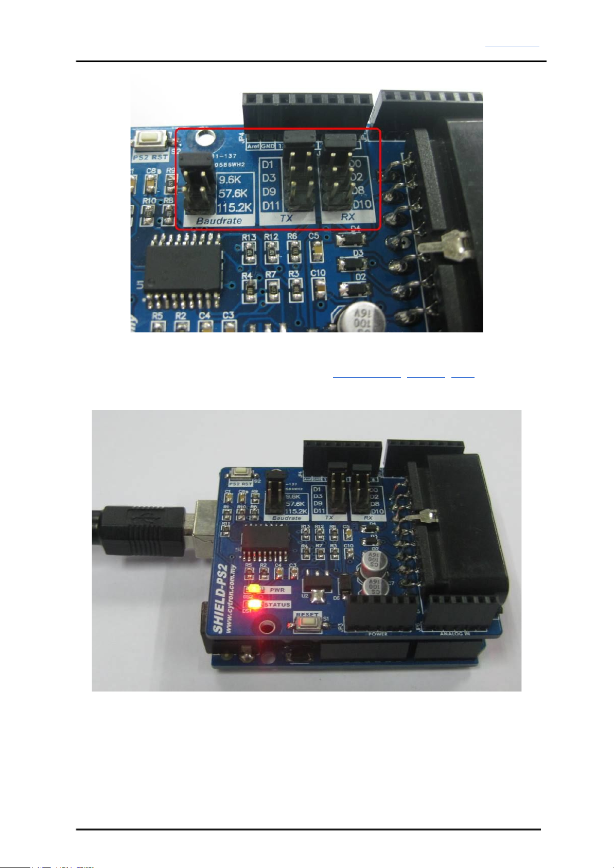
●5V powered, low current consumption.
●Simple to use UART protocol
●Vibrator motor on PS2 is controllable.
●Wired and Wireless PS2 controller is supported.
●PS2 Controller will automatically operate in analog mode.
●A status LED
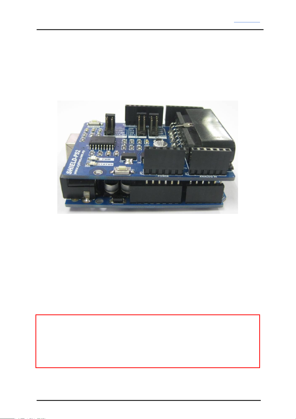
●Jumper selector to select different UART Baud Rate (4800, 9600, 57600, 115200).
●Jumper selectors to select different digital pin as UART TX and RX pin.
Created by Cytron Technologies Sdn. Bhd. – All Rights Reserved 3

ROBOT . HEAD to TOE
Product User’s Manual – Shield-PS2
3.0 PRODUCT SPECIFICATION AND LIMITATIONS
Dimensions
No
Parameters
Min
Typical
Max
Unit
1
Input Voltage (Logic Operation Voltage)
4.5
-
5.5
V
2
Current Consumption
100
150
500
mA
3
VIOH (Logic Input – High Level)
3.5
5.0
5.5
V
4
VIOL (Logic Input – Low Level)
0
0
1.0
V
Created by Cytron Technologies Sdn. Bhd. – All Rights Reserved 5

ROBOT . HEAD to TOE
Product User’s Manual – Shield-PS2
4.0 PRODUCT LAYOUT
Components on Shield-PS2 and their functions:
1. Stackable Analog Input Header
This is the analog port of the Arduino. The stackable header allows other stacked
shield to utilize these pins.
2. Stackable Power Pins Header
This is the power port of the Arduino. The stackable header allows other stacked
shield to utilize these pins.
3. Main Board reset button
Arduino main board will require around 30ms to ready after reset.
Created by Cytron Technologies Sdn. Bhd. – All Rights Reserved 6

ROBOT . HEAD to TOE
Product User’s Manual – Shield-PS2
4. Status indicator LED (Orange)
This LED will blink and illuminate with different brightness depending on the PS2
status.
LED Condition
Description
Blink with
different brightness
Once power up, if there is no SONY PS2 controller connected or
detected..
Stay illuminated
with low brightness
SONY PS2 controller detected and communication is working fine.
Stay illuminated
with high
brightness
Digital button on SONY PS2 controller is pressed.
5. Power indicator LED (Green)
Indicator to shows that power is supplied to Cytron PS2 Shield.
6. Baud Rate selector
To select the preferable UART baud rate For Cytron PS2 Shield to obtain latest
baudrate from selector, Shield-PS2 need to be reset to update the board’s baud rate.
7. On board Cytron PS2 Shield reset button
PS2 RST button will only reset the SHIELD-PS2 but not the Arduino Main board.
8. Stackable Digital I/O Headers
JP4 and JP7 are Digital I/O pins stacked to the Arduino main board.
9. RX Pin Selector
User may select D0, D2, D8 or D10 as the RX pin from Arduino main board with the
mini jumper. If Arduino UNO or Mega is used, recommended to move the RX pin
selector to D2, D8 or D10 as D0 is used for bootloader (loading program).
10. TX Pin Selector
User may select D1, D3, D9 or D11 as the TX pin from Arduino main board with the
mini jumper. If Arduino UNO or Mega is used, recommended to move the TX pin
selector to D3, D9 or D11 as D1 is used for bootloader (loading program).
11. SONY PS2 Connector Socket
Please connect PS2 Controller plug here, wireless or wired.
Created by Cytron Technologies Sdn. Bhd. – All Rights Reserved 7

ROBOT . HEAD to TOE
Product User’s Manual – Shield-PS2
5.0 HARDWARE INTERFACE
This section shows the example of using SHIELD-PS2 with Arduino UNO as the main
controller. However, other Arduino main board such as Arduino Duemilanove and Arduino
Mega can also be used.
Figure below shows that the SHIELD-PS2 is stacked on the Arduino UNO. Please ensure that
the pins alignment is correct.
Select the pins for UART’s TX and RX. Pin D0 and D1 are hardware serial of most arduino
main board. Other selectable pin for TX and RX on Shield-PS2 are software serial pin. The
default TX pin is set to D3 while the RX pin is set to D2. However, other pins may be
selected if these pins are already used by other application. If hardware serial pin (D0, D1) is
selected, user needs to unplug the PS2 Connector from the Shield-PS2 before start to
program the main board. Programming of main board may fail if the Shield-PS2 is stacked on
mainboard and PS2 controller connector is connected. Select desired baudrate for Shield-PS2
using the mini jumper.
Guideline to choose pin for software serial:
Not all pins on the Mega and Mega 2560 support change interrupts,
so only the following can be used for RX:
10, 11, 12, 13, 50, 51, 52, 53, 62, 63, 64, 65, 66, 67, 68, 69
Not all pins on the Leonardo support change interrupts,
so only the following can be used for RX:
8, 9, 10, 11, 14 (MISO), 15 (SCK), 16 (MOSI).
Created by Cytron Technologies Sdn. Bhd. – All Rights Reserved 8

ROBOT . HEAD to TOE
Product User’s Manual – Shield-PS2
USB cable to Arduino main board and load example code. Sample source code and
Arduino’s Library can be downloaded from the SHIELD-PS2 product page at Cytron’s
website.
Connect the PS2 joystick to the PS2 connector socket on SHIELD-PS2 as shown. Don’t
forget about the power source for the Arduino main board too. Power source for the Arduino
main board is from DC adaptor plug.
Created by Cytron Technologies Sdn. Bhd. – All Rights Reserved 9

ROBOT . HEAD to TOE
Product User’s Manual – Shield-PS2
5.1 Choose SONY PS2 DualShock Controller
There are many types of PS2 controller in the market with different sensitivity. User are free
to choose any type of them. However, it is advised to use the PS2 controller from Cytron
Technologies. We do not guarantee the compatibility for all PS2 controllers from other
sources. You can check the PS2 controller that are available in our store here.
No modification is needed to connect to PS2 shield.
Wired PS2 Controller
Wireless PS2 Controller
Created by Cytron Technologies Sdn. Bhd. – All Rights Reserved 11

ROBOT . HEAD to TOE
Product User’s Manual – Shield-PS2
Figure below shows the digital buttons and analog joystick on a typical PS2 controller.
The analog value of Left Joystick and Right Joystick can be read from shield-PS2 too. Each
joystick have 2 axes, and there are two formats of output. These formats will be explained
later. User may choose format 1 or format 2.
NOTE:
SONY PS2 controller does not come with PS2 Shield, please purchase separately from
Cytron Technologies website. It is advised to use PS2 controller from Cytron Technologies
because all PS2 controller is tested before it is being shipped to customer.
Created by Cytron Technologies Sdn. Bhd. – All Rights Reserved 12

ROBOT . HEAD to TOE
Product User’s Manual – Shield-PS2
Analog output format 1:
There are 2 variables for each joystick, axis X and axis Y, this is what we commonly use in
graph drawing. On PS2 joystick, as example, when user push the joystick up or down, the Y
axis will change. Meanwhile if user push the joystick left or right, the value of X axis will
change.
Y Axis:
●Middle (neutral), value is 128
●Push up, value change from 128 to 0
●Push down, value change from 128 to 255.
X Axis:
●Middle(neutral, value is 128
●Push towards left, value change from 128 to 0
●Push towards right, value change from 128 to 255
Left joystick have X axis and Y axis, Right joystick also have its own X and Y axis.
Analog value of Format 1
Taking an example, let’s say the left joystick is being push to the position shown in the
figure. It is being push to left top corner. The value of left joystick will change will should get
approximately:
●j_lx = 70
●j_ly = 92
This is just an example, we notice a lot of PS2 joystick do not provide linear analog value
across the range. There is a big dead zone near the middle position where analog value does
not change. User is required to “play” around with the joystick.
Created by Cytron Technologies Sdn. Bhd. – All Rights Reserved 13

ROBOT . HEAD to TOE
Product User’s Manual – Shield-PS2
Analog output format 2:
In format 2, there are four variables for each joystick. The four variables are up, down, left
and right. When user move the joystick in any direction, the value of these four variables
change from 0 to 100. Left and Right joystick will have 4 independent variables.
Analog value of Format 2
Taking an example, let’s say the left joystick is being pushed to the position shown in the
figure. It is being push to left down corner. The value of left joystick will change will should
get approximately:
●j_ll = 10
●j_ld = 50
You can choose whichever format to use by sending particular command to PS2 Shield.
Please do take note that the the format 1 variables are:
●j_lx - Left joystick, X axis
●j_ly - Left joystick, Y axis
●j_rx - Right joystick, X axis
●j_ry - Right joystick, Y axis
Format 2 variables are:
●j_lu - Left joystick, up axis
●j_ld - Left joystick, down axis
●j_ll - Left joystick, left axis
●j_lr - Left joystick, right axis
●j_ru - Right joystick, up axis
●j_rd - Right joystick, down axis
●j_rl - Right joystick, left axis
●j_rr - Right joystick, right axis

ROBOT . HEAD to TOE
Product User’s Manual – Shield-PS2
l - mean Left joystick
r - mean Right joystick
x - mean X axis, format 1, range 0 to 255
y - mean Y axis, format 1, range 0 to 255
u - mean Up axis, format 2, range 0 to 100
d - mean Down axis, format 2, range 0 to 100
l - mean Left axis, format 2, range 0 to 100
r - mean Right axis, format 2, range 0 to 100

ROBOT . HEAD to TOE
Product User’s Manual – Shield-PS2
6. PROTOCOL
By default, Shield-PS2 is in passive condition, where it waits for command from UART. If
Arduino main board sends a command, it will response based on the command and the status
of PS2 button and joystick. The command is simple, it is in value. Each value will request
Shield-PS2 to check the particular button or joystick status on PS2 and response.
6.1 PS2 Button and Joystick Status
Send
(decimal)
Button on PS2
Description
0
1
2
3
4
5
6
7
8
9
10
11
12
13
14
15
Select button
left joystick centre button
right joystick centre
button
START button
up button
right button
down button
left button
L2 button
R2 button
L1 button
R1 button
triangle button
circle button
cross button
square button
Applied to value 0 to 15 (decimal):
Shield-PS2 will return the status of
corresponding button when the particular
decimal value is received
0 if the button is pressed
1 if button is not pressed
Example:
If main board sent 10 (decimal), Shield-PS2
will check L1 button status on PS2 Controller.
Shield-PS2 will return:
0 if L1 button is pressed or
1 if L1 is not pressed.
16
17
18
left joystick x-axis
left joystick y-axis
right joystick x-axis
Created by Cytron Technologies Sdn. Bhd. – All Rights Reserved 16

ROBOT . HEAD to TOE
Product User’s Manual – Shield-PS2
19
20
21
22
23
24
25
26
27
right joystick y-axis
left joystick up value
left joystick down value
left joystick left value
left joystick right value
right joystick up value
right joystick down value
right joystick left value
right joystick right value
Applied to value from 16 to 27 (decimal):
Shield-PS2 will return the particular value of
corresponding joystick in the selected axis
Example :
If main board sent 20 (decimal), Shield-PS2
will read and return the value of left joystick
up.
28
Return the connection
status of PS2 controller on
Shield-PS2
Shield-PS2 will read PS2 controller status
1 is returned if controller is detected or
connected to the PS2 connector on Shield-PS2
6.2 On board Vibrator Motor Control
Following commands require two bytes of data send from main board. 1st byte to indicates
which vibrator motor, following byte (2nd byte) to indicator motor status or the speed.
send 1st byte
(decimal)
send 2nd byte
(decimal)
Controller
Description
29
motor1 value
smaller vibrator on right
motor1 = 1 (motor on)
motor1 = 0 (motor off)
30
motor2 value
bigger vibrator on left
motor2 = 0 to 255
(adjustable speed)
Created by Cytron Technologies Sdn. Bhd. – All Rights Reserved 17

ROBOT . HEAD to TOE
Product User’s Manual – Shield-PS2
6.3 All PS2 Button and Joystick Status
Send
(decimal)
Response from PS2
Description
31
6 bytes of data:
1st byte: digital button group
1
2nd byte: digital button
group 2
3rd byte: Right Joystick X
axis
4th byte: Right Joystick Y
axis
5th byte: Left Joystick X axis
6th byte: Left Joystick Y axis
Shield-PS2 will return the status of all
digital and analog joystick of PS2
Digital group 1:
bit 7 (MSB): Left button
bit 6: Down button
bit 5: Right button
bit 4: Up button
bit 3: Start button
bit 2: Right Joystick Center button
bit 1: Left Joystick Center button
bit 0 (LSB): Select button
Digital group 2:
bit 7 (MSB): Square button
bit 6: Cross button
bit 5: Circle button
bit 4: Triangle button
bit 3: R1 button
bit 2: L1 button
bit 1: R2 button
bit 0 (LSB): L2 button
0 if the button is pressed
1 if button is not pressed
Example:
If microcontroller sent 31 (decimal),
Shield-PS2 will check all the button
and joystick status and return 6 bytes
to microcontroller.
Created by Cytron Technologies Sdn. Bhd. – All Rights Reserved 18

ROBOT . HEAD to TOE
Product User’s Manual – Shield-PS2
Examples:
Example of UART communication shows main board obtain the Circle button of PS2
Example of UART communication shows mainboard obtain the Left jostick, X axis value of
PS2
Created by Cytron Technologies Sdn. Bhd. – All Rights Reserved 19

ROBOT . HEAD to TOE
Product User’s Manual – Shield-PS2
7.0 WARRANTY
●Product warranty is valid for 12 months.
●Warranty only applies to manufacturing defect.
●Damaged caused by misuse is not covered under warranty
●Warranty does not cover freight cost for both ways.
Prepared by:
Cytron Technologies Sdn. Bhd.
No. 16, Jalan Industri Ringan Permatang Tinggi 2,
Kawasan Industri Ringan Permatang Tinggi,
14100 Simpang Ampat,
Penang, Malaysia.
Tel: +604 - 504 1878
Fax: +604 - 504 0138
URL: www.cytron.com.my
Email:
Created by Cytron Technologies Sdn. Bhd. – All Rights Reserved 20
Other manuals for Shield-PS2
1
Table of contents
Other Cytron Technologies Carrier Board manuals