Cytron ESPWiFi Shield User manual

ROBOT . HEAD to TOE
Product User’s Manual – ESPWiFi Shield Rev2.0
Index
1. Introduction 3
2. Packing List 4
3. Board or Product Layout 5
4. Dimension 7
5. UART/Serial Communication 8
6. Hardware Installation 9
7. Getting Started 10
8. Firmware Installation 14
9. Warranty 14
Created by Cytron Technologies Sdn. Bhd. – All Right Reserved 2

ROBOT . HEAD to TOE
Product User’s Manual – ESPWiFi Shield Rev2.0
1.0 INTRODUCTION
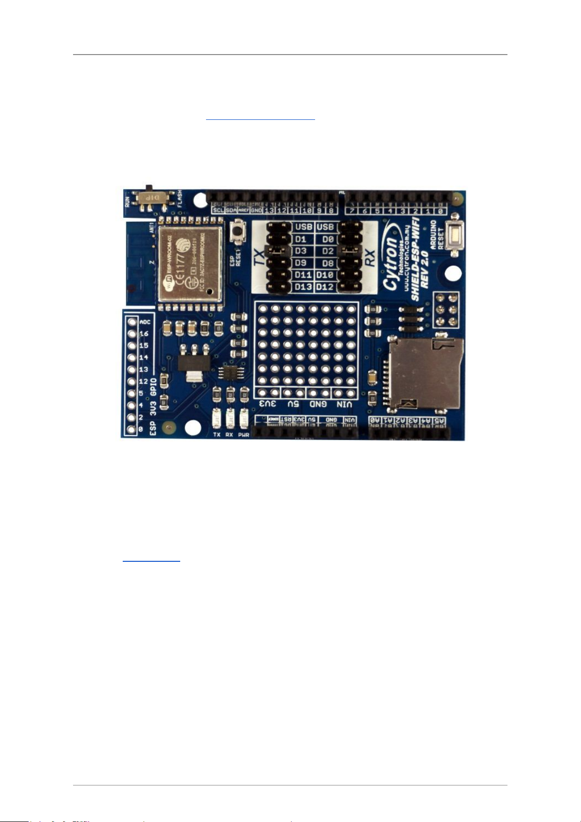
ESPWiFi Shield Rev2.0 is an Arduino shield which integrates famous ESP-WROOM-02
WiFi module and provides low cost WiFi solution with any Arduino projects. It is compatible
with Arduino Uno,Arduino Duemilanove,Arduino Mega2560,Arduino Leonardo and
possibly other pin compatible main boards.
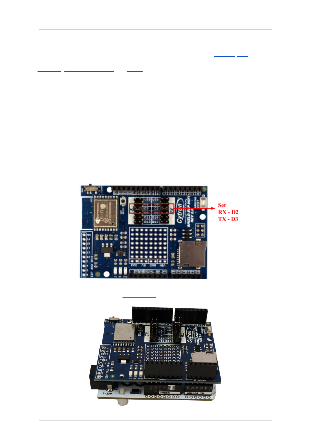
ESP8266 WiFi shield provides easy and stable UART interface for users to communicate
with onboard WiFi module using Arduino boards. The module is preloaded with AT
firmware and the user can use provided library to implement WiFi solution in their Arduino
projects. Advanced users can even customise and upload their own firmware on this ESP8266
module and use it as an additional microcontroller to create an even more powerful
application together with Arduino boards.
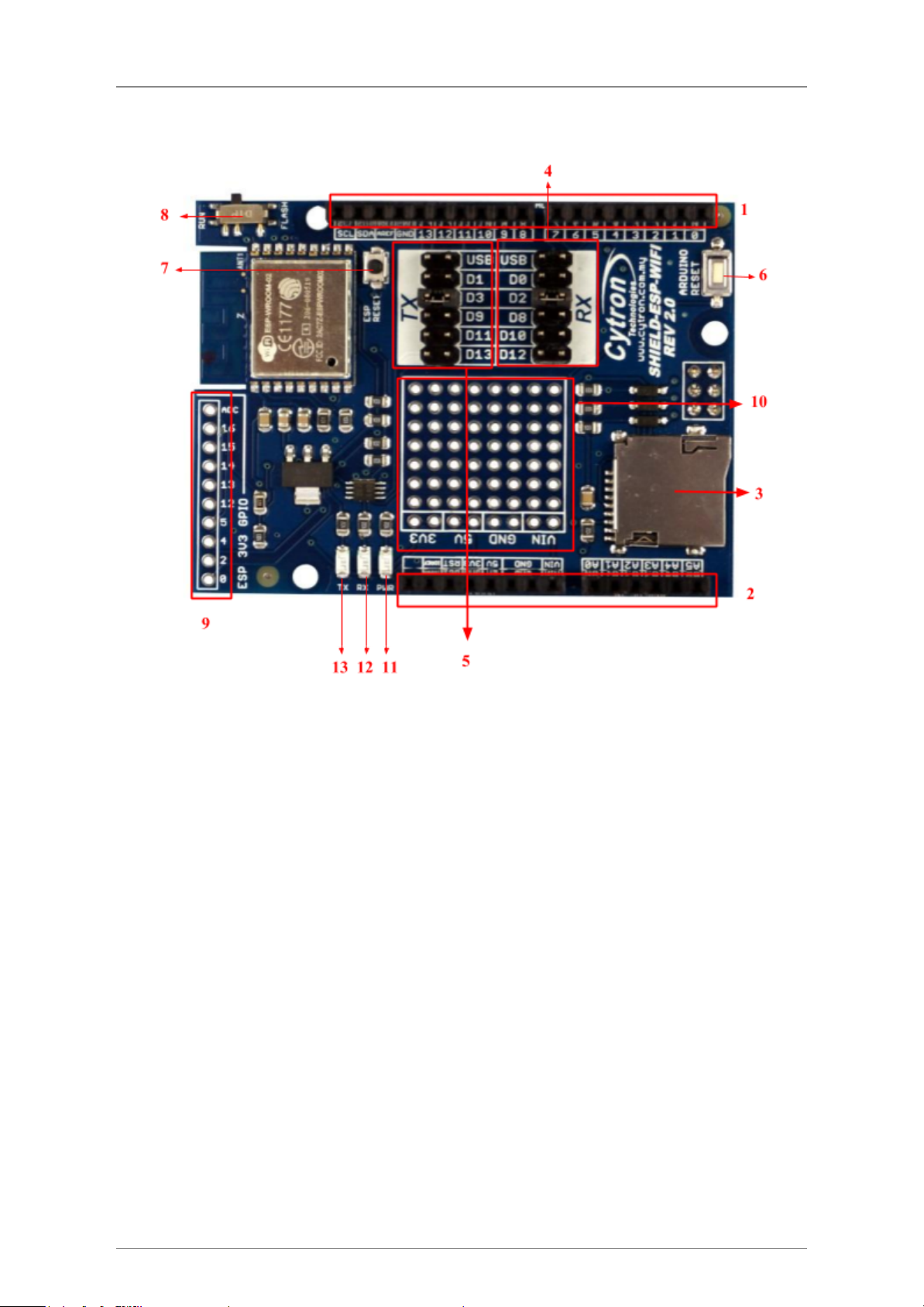
ESP8266 WiFi shield has stackable side headers which allows more Arduino-compatible
shields to be stacked on top of it. This shield provides digital pins options for software and
hardware UART or even PC-ESP communication. It also provides GPIO pin breakout and a
small prototyping area for the users to construct small circuits suitable to their application.
The shield also comes with microSD slot which serves as extra file storage for the users.
Features:
●Onboard ESP-WROOM-02 WiFi module with preloaded AT firmware
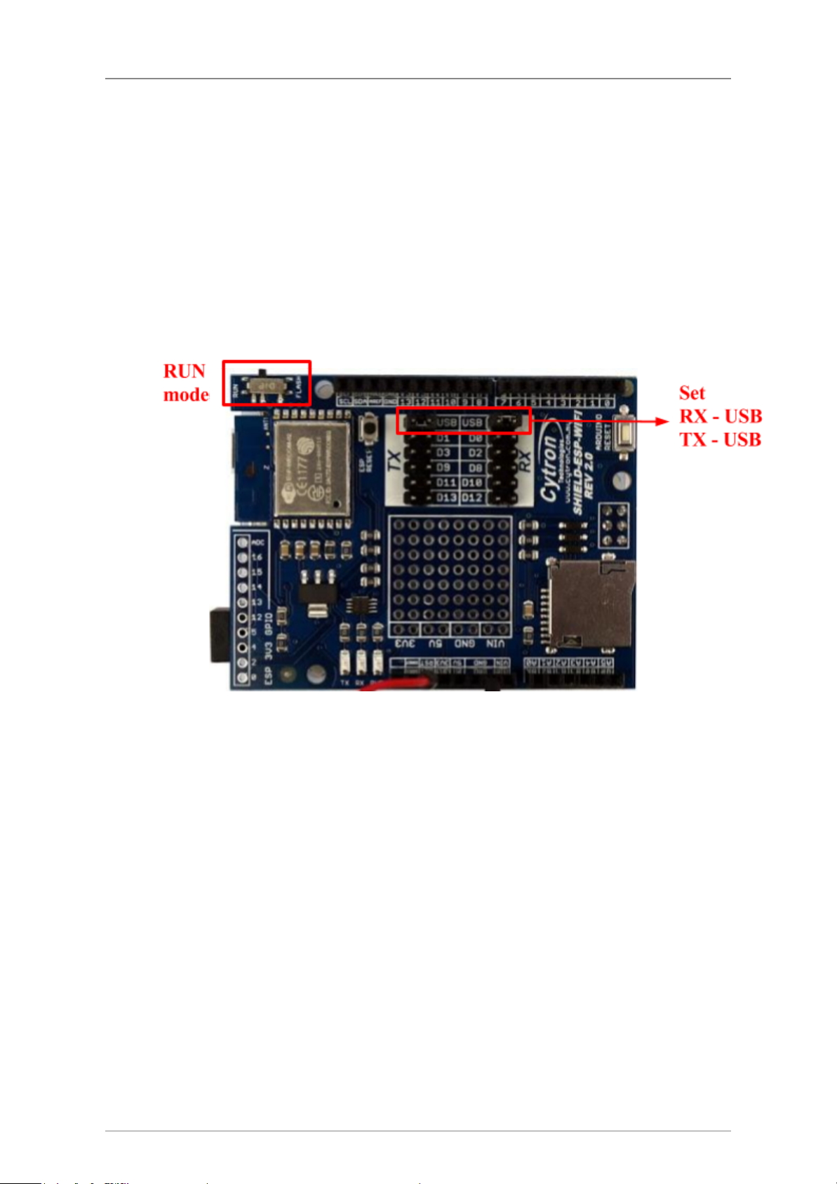
●Jumper selectors for software or hardware UART and PC-ESP communication.
●TX and RX LED indicators for ESP8266 WiFi module.
●ESP8266 3V3 GPIO pin breakout (including 9 digital I/O pins and 1 analog input pin)
●Prototyping area
●1 MicroSD card slot.
●Arduino Reset and ESP8266 Module Reset button.
Created by Cytron Technologies Sdn. Bhd. – All Right Reserved 3

ROBOT . HEAD to TOE
Product User’s Manual – ESPWiFi Shield Rev2.0
2.0 PACKING LIST
Please check the parts and components according to the packing lists. If there are any parts
1. 1 x ESPWiFi Shield
2. 2 x mini jumper
Created by Cytron Technologies Sdn. Bhd. – All Right Reserved 4

ROBOT . HEAD to TOE
Product User’s Manual – ESPWiFi Shield Rev2.0
3.0 BOARD OR PRODUCT LAYOUT
1. Stackable Digital I/O header
This header pin is Digital I/O pin stacked to the Arduino main board. Other Arduino shield
can be stacked on top of this stackable header.
2. Stackable Analog Input pin header
This header pin is Analog Input pin stacked to the Arduino main board. Other Arduino shield
can be stacked on top of this stackable header.
3. MicroSD card chip select (CS)
Digital Pin 4 is used as chip select for MicroSD card. Do not make any other connection to
this pin.
4. RX Pin Selector
User may select D0, D2, D8, D10 and D12 as the RX pin from Arduino main board with the
mini jumper.
5. TX Pin Selector
User may select D1, D3, D9, D11 and D13 as the TX pin from Arduino main board with the
mini jumper.
6. Arduino Reset button
Reset button is for convenience of user to reset the Arduino main board.
Created by Cytron Technologies Sdn. Bhd. – All Right Reserved 5

ROBOT . HEAD to TOE
Product User’s Manual – ESPWiFi Shield Rev2.0
7. ESP Reset button
Reset button is for convenience of user to reset the onboard ESP8266 module.
8. Flash/Run slide switch
Slide switch is for convenience of user to select which mode ESP8266 module will enter
once powered up.
Flash mode - the mode which ESP8266 module wait for firmware installation/update
Run mode - the mode which ESP8266 module run the installed firmware
9. ESP 3V3 GPIO breakout
Pin breakout from ESP8266 GPIO, consists of 9 Digital I/O pins and 1 Analog Input pin. All
pins are 3.3V tolerant only.
10. Prototyping Area
Prototyping area for users to construct small circuits suitable to their applications.
11. Power LED
Power indicator LED for onboard ESP8266 module. The LED will turn on when 5V power is
supplied to the module.
12. RX Indicator LED
RX LED as indicator for RX signal from ESP8266.
13. TX Indicator LED
TX LED as indicator for TX signal from ESP8266.
Created by Cytron Technologies Sdn. Bhd. – All Right Reserved 6

ROBOT . HEAD to TOE
Product User’s Manual – ESPWiFi Shield Rev2.0
5.0 UART/SERIAL COMMUNICATION
AT firmware of the ESP8266 WiFi module on ESPWiFi shield allows users to communicate
with the module using UART communication.
Default settings are 9600 kbps baudrate, 8 bit data, 1 stop bit and no parity.
5.1 Guideline for setting up TX and RX pin with Arduino Boards
The following table shows suitable RX and TX pins to be chosen for compatible Arduino
boards.
UART
Arduino Boards
RX
TX
USB*
USB*
Arduino Uno/Arduino Mega/Arduino Leonardo
D0
D1
Arduino Uno/Arduino Mega/Arduino Leonardo
D2
D3
Arduino Uno only
D8
D9
Arduino Uno/Arduino Leonardo
D10
D11
Arduino Uno**/Arduino Mega/Arduino Leonardo
D12
D13
Arduino Uno**/Arduino Mega
* This option enables communication between ESP8266 module and PC using suitable
UART software such as Arduino Serial Monitor, Hyperterminal, RealTerm etc.
** Only applicable if no SPI communication is used because SPI pinouts uses D10-D13
in Arduino Uno. MicroSD card cannot be used as well in this case.
Created by Cytron Technologies Sdn. Bhd. – All Right Reserved 8

ROBOT . HEAD to TOE
Product User’s Manual – ESPWiFi Shield Rev2.0
6.0 HARDWARE INSTALLATION
This section will show example installation of ESPWiFi Shield with Arduino Uno as a main
controller. Besides Arduino Uno, other Arduino main boards such as Arduino Duemilanove,
CT-UNO, Arduino Mega2560 and CIKU are also compatible with this shield.
6.1 Arduino Uno
Arduino is an open-source physical computing platform based on a simple I/O board and a
development environment that implements the Processing/Wiring language. ESPWiFi Shield
can be used together with Arduino Uno. Figure below shows example hardware connection
between Arduino Uno and ESPWiFi Shield; it is simply stacking up the shield onto the
Arduino main board.
1. Set TX and RX pin for ESPWiFi Shield. The selection is done by using mini jumper
on board. Please refer to Section 5.1 for suitable RX and TX pin selection.
2. Please be cautious to initialize the correct Arduino’s digital pin in coding/software
according to the selected TX and RX pins for the communication. We recommend
user to use software serial (D3-TX, D2-RX) instead of hardware serial.
3. Stack ESPWiFi Shield on Arduino Uno. Ensure that the pins alignment is correct.
Created by Cytron Technologies Sdn. Bhd. – All Right Reserved 9

ROBOT . HEAD to TOE
Product User’s Manual – ESPWiFi Shield Rev2.0
7.0 GETTING STARTED
This section will show examples of using ESPWiFi Shield together with Arduino Board to
1) perform AT test - basic module testing by sending AT commands
2) create a simple WiFi server
7.1 AT Test
1. Stack ESPWiFi Shield onto compatible Arduino Board. For this example, Arduino
Uno is used.
2. Select USB for both RX and TX pins. **Note: This setting is only for entering AT
command.
3. Make sure the slide switch is switched to RUN mode.
4. **Note: For AT Test, connect RST pin to GND using jumper wire. (Another
alternative, upload an empty sketch to Arduino main board before stacking
ESPWiFi Shield onto Arduino board.)
5. Connect Arduino board to PC using USB cable.
6. Open Arduino IDE. Determine which COM port Arduino Uno is connected to and
configure the port settings under menu Tools -> Port.
7. Open and set up Arduino Serial Monitor with settings below.
●9600 Baud
●Both NL & CR
8. Figure below shows sending “AT” using Arduino Serial Monitor. If the result returns
“OK”, it means you have successfully communicate with the ESP8266 module on
ESPWiFi Shield, AT test is successful. User can also try out other AT commands like
AT+GMR, etc.
Created by Cytron Technologies Sdn. Bhd. – All Right Reserved 10

ROBOT . HEAD to TOE
Product User’s Manual – ESPWiFi Shield Rev2.0
7.2 Create a simple WiFi server using Arduino Uno + ESPWiFi Shield
1. Stack ESPWiFi Shield onto compatible Arduino Board. For this example, Arduino
Uno is used.
2. Select D2 for RX and D3 for TX pin.
3. Make sure the slide switch is switched to RUN mode.
4. Download CytronWiFiShield library from link provided at product page and extract
the files to My Documents -> Arduino -> Libraries.
Created by Cytron Technologies Sdn. Bhd. – All Right Reserved 11

ROBOT . HEAD to TOE
Product User’s Manual – ESPWiFi Shield Rev2.0
5. Connect Arduino board to PC using USB cable.
6. Open Arduino IDE. Determine which COM port Arduino Uno is connected to and
configure the port settings under menu Tools -> Port.
7. Go to File -> Examples -> CytronWiFiShield and open example sketch
CytronWiFiDemo.
8. Change ssid from “...” to your network name and “pass” to corresponding password.
For example, your network router SSID is WiFly and password is abcd.
const
char
*ssid
=
"WiFly";
const
char
*pass
=
"abcd";
9. Check the line wifi.begin(2, 3). 1st argument for this function refers to RX of Arduino
and 2nd refers to TX. If D2 is selected for RX and D3 for TX on ESPWiFi Shield, the
configuration is correct.
10. Upload the program to Arduino board.
11. Open Arduino Serial Monitor to view the progress. Setup to 9600 baud.
12. Make sure PC is connected to the same internet network with the ESPWiFi Shield.
13. Observe the IP Address shown in Serial monitor. Enter the IP Address using any web
browsers (Google Chrome, Mozilla Firefox, etc.)
Created by Cytron Technologies Sdn. Bhd. – All Right Reserved 12

ROBOT . HEAD to TOE
Product User’s Manual – ESPWiFi Shield Rev2.0
14. If the webpage returns what have shown in the following figure, the program is
working. For the example here, IP address shown in Serial monitor is 192.168.1.242.
Created by Cytron Technologies Sdn. Bhd. – All Right Reserved 13

ROBOT . HEAD to TOE
Product User’s Manual – ESPWiFi Shield Rev2.0
8.0 FIRMWARE INSTALLATION
ESP8266 3V3 GPIO Input and Output function has deprecated with preloaded AT firmware
on ESP-WROOM-02 module on ESPWiFi Shield. However, Cytron Technologies offers
customised AT firmware which adds the stated capability to the module, allowing user to
utilise the 3V3 GPIO fully in the applications. User can follow the guide below to install new
AT firmware to the module.
Hardware configuration
1. Stack the shield onto Arduino compatible board. In this example, Arduino Uno is
used.
2. Place both mini jumpers on USB selection.
3. **IMPORTANT!! Connect RST to GND using jumper wire to make sure the board
reset at all times (Another alternative, upload an empty sketch to Arduino Uno before
stacking the shield onto it)
4. Slide the slide switch to FLASH mode.
5. Connect the whole board (Arduino Uno + ESPWiFi shield) to PC via USB cable.
6. Press ESP Reset button (with slide switch switched to FLASH mode) to enable
FLASH mode of ESP-WROOM-02 module.
Created by Cytron Technologies Sdn. Bhd. – All Right Reserved 14

ROBOT . HEAD to TOE
Product User’s Manual – ESPWiFi Shield Rev2.0
Install AT Firmware
●Windows (for Windows user only)
1. Download latest ESPWIFI_Shield_Firmware from link provided at product
page. Extract it. Enter the folder, go to install_firmware -> windows.
2. Open ESP_DOWNLOAD_TOOL_V2.4.exe.
3. Choose the COM port Arduino Uno + ESPWiFi shield connecting to. Set the
BAUDRATE to 115200.
4. Make sure ESP-WROOM-02 module is in FLASH mode (step 4 and 6 in
Hardware Configuration)
5. Click START to install the firmware.
Created by Cytron Technologies Sdn. Bhd. – All Right Reserved 15

ROBOT . HEAD to TOE
Product User’s Manual – ESPWiFi Shield Rev2.0
●Linux (for Linux user only)
1. Download latest ESPWIFI_Shield_Firmware from link provided at product
page. Extract it. Enter the folder, go to install_firmware -> linux.
2. Make sure ESP-WROOM-02 module is in FLASH mode (step 4 and 6 in
Hardware Configuration)
3. Open terminal here and run following line to start firmware installation.
$ ./flash.sh <the port Arduino Uno + ESPWiFi shield connecting to>
E.g $./flash.sh /dev/ttyACM0
AT Test and some minor configuration
1. Open Arduino Serial Monitor. Make sure the serial port is same as the port Arduino
Uno + ESPWiFi shield connecting to.
2. Open and set up Arduino Serial Monitor with settings below.
●115200 Baud
●Both NL & CR
3. Switch the slide switch to RUN mode.
4. Press ESP reset button. If there is a word “ready” shown in monitor, the firmware
installation is successful and the firmware is working properly.
5. Enter the command AT+UART=9600,8,1,0,0
6. After the monitor shows “OK” in return, change to 9600 Baud.
7. Test the module with several commands like AT and AT+GMR. If there are replies
from these commands, UART setup is successful.
8. The shield is now ready for WiFi library implementation. Remember to switch TX
and RX jumpers to D2 and D3 or other pairs according to your arduino sketch.
Created by Cytron Technologies Sdn. Bhd. – All Right Reserved 16

ROBOT . HEAD to TOE
Product User’s Manual – ESPWiFi Shield Rev2.0
9.0 WARRANTY
●Product warranty is valid for 6 months.
●Warranty only applies to manufacturing defect.
●Damaged caused by misuse is not covered under warranty
●Warranty does not cover freight cost for both ways.
Prepared
by
Cytron
Technologies
Sdn.
Bhd.
No. 16, Jalan Industri Ringan Permatang Tinggi 2,
Kawasan Industri Ringan Permatang Tinggi,
14100 Simpang Ampat,
Penang, Malaysia.
Tel: +604
-
504
1878
Fax: +604
-
504
0138
URL: www.cytron.com.my
Email:
Created by Cytron Technologies Sdn. Bhd. – All Right Reserved 17
This manual suits for next models
1
Table of contents