Luna POD 2000 User manual

DOC000000_POD 2000 Guide Rev 1.0
User Manual │POD 2000

POD 2000
DOC000000_POD 2000 User Manual Rev001
Page 1
Many regions prohibit the disposal of WEEE (Waste Electrical and
Electronic Equipment) in the normal waste stream, to comply with the
Restriction of Hazardous Substances (RoHS) released into the
environment. Please contact your local waste authority for instructions on
proper recycling of the electronic product(s) described in this User
Manual.
POD 2000 User Manual
© 2023
Luna Innovations Inc.
3155 State Street
Blacksburg, VA 24060
Phone: (866) 586-2682
Fax: (540) 961-5191
E-mail: [email protected]
Web: www.lunainc.com

POD 2000
DOC000000_POD 2000 User Manual Rev001
Page 2
Table of Contents
1. Safety .................................................................................................................................................... 6
2. Technical Support ................................................................................................................................. 7
2.1. Mail ............................................................................................................................................... 7
2.2. Phone ........................................................................................................................................... 7
2.3. E-mail ............................................................................................................................................ 7
3. Overview .............................................................................................................................................. 8
4. Hardware and Physical Setup ............................................................................................................... 9
4.1. Unpacking ..................................................................................................................................... 9
4.2. Communication Connection ......................................................................................................... 9
4.2.1. USB Communications ........................................................................................................... 9
4.2.2. Ethernet Communications .................................................................................................... 9
4.3. Starting the system ....................................................................................................................... 9
4.4. Shutting the system down ............................................................................................................ 9
5. POD 2000 PC software ....................................................................................................................... 10
5.1. Installation Package .................................................................................................................... 11
5.1.1. System Requirements ......................................................................................................... 11
5.1.2. Software Installation .......................................................................................................... 11
5.1.3. Software Removal .............................................................................................................. 11
5.2. User interface overview ............................................................................................................. 12
5.3. Opening and Closing Devices ...................................................................................................... 13
5.3.1. Setting the Active Device .................................................................................................... 13
5.3.2. Closing Devices ................................................................................................................... 14
5.4. Measurement Data viewer ......................................................................................................... 14
5.4.1. Poincaré Sphere and Polarization parameters SOP ............................................................ 14
5.4.2. Oscilloscope viewer and Polarization parameters .............................................................. 16
5.4.3. Long-Term data viewer ....................................................................................................... 17
5.5. User interface menu and setup .................................................................................................. 18
5.5.1. File Tab ............................................................................................................................... 18
5.5.2. Device Tab .......................................................................................................................... 18
5.5.3. View Tab ............................................................................................................................. 18
5.5.4. Help Tab .............................................................................................................................. 18

POD 2000
DOC000000_POD 2000 User Manual Rev001
Page 3
5.5.5. Settings ............................................................................................................................... 19
5.5.5.1. Basic Settings .................................................................................................................. 19
5.5.5.2. Work Mode Settings ....................................................................................................... 19
6. Remote Control Configuration ........................................................................................................... 20
6.1. USB Configuration and Programming Guide .............................................................................. 20
6.2. TCP/IP Configuration and Programming Guide .......................................................................... 20
7. Standard Commands for Programmable Instruments (SCPI) Interface .............................................. 20
7.1 Overview .................................................................................................................................... 21
7.2 Commands Reference ................................................................................................................ 22
7.2.1 IEEE 488.2 Commands ........................................................................................................ 22
7.2.1.1 *IDN? .............................................................................................................................. 22
7.2.1.2 *RST ................................................................................................................................ 22
7.2.1.3 *CLS ................................................................................................................................ 23
7.2.1.4 *STB? .............................................................................................................................. 23
7.2.1.5 *SRE ................................................................................................................................ 23
7.2.1.6 *SRE? .............................................................................................................................. 23
7.2.1.7 *ESR? .............................................................................................................................. 23
7.2.1.8 *ESE ................................................................................................................................ 23
7.2.1.9 *ESE? .............................................................................................................................. 23
7.2.1.10 *WAI ........................................................................................................................... 23
7.2.1.11 *OPC ........................................................................................................................... 23
7.2.1.12 *OPC? ......................................................................................................................... 24
7.2.1.13 *TST? .......................................................................................................................... 24
7.2.1.14 *SAV ............................................................................................................................ 24
7.2.1.15 *RCL ............................................................................................................................ 24
7.2.1.16 *TRG ........................................................................................................................... 24
7.2.2 :SYSTem Subsystem ............................................................................................................ 24
7.2.2.1 :SYSTem:COMMunicate:LAN:ADDRess ........................................................................... 24
7.2.2.2 :SYSTem:COMMunicate:LAN:SUBN ................................................................................ 25
7.2.2.3 :SYStem:COMMunicate:LAN:GATEway .......................................................................... 25
7.2.2.4 :SYStem:COMMunicate:LAN:DHCP ................................................................................. 25
7.2.2.5 :SYStem:COMMunicate:ANCillary .................................................................................. 26

POD 2000
DOC000000_POD 2000 User Manual Rev001
Page 4
7.2.2.6 :SYStem:ERRor[:NEXT]? .................................................................................................. 26
7.2.2.7 :SYStem:VERSion? ........................................................................................................... 26
7.2.3 :STATus Subsystem ............................................................................................................. 26
7.2.3.1 :STATus:OPERation[:EVENt]? .......................................................................................... 26
7.2.3.2 :STATus:OPERation:CONDition? ..................................................................................... 27
7.2.3.3 :STATus:OPERation:ENABle ............................................................................................ 27
7.2.3.4 :STATus:QUEStionable[:EVENt]? ..................................................................................... 27
7.2.3.5 :STATus:QUEStionable:CONDition? ................................................................................ 27
7.2.3.6 :STATus:QUEStionable:ENABle ....................................................................................... 27
7.2.3.7 :STATus:PRESet ............................................................................................................... 28
7.2.4 :CONFigure Subsystem ....................................................................................................... 28
7.2.4.1 :CONFigure:GAIN[:VALue] .............................................................................................. 28
7.2.4.2 :CONFigure:GAIN:LPRange? ........................................................................................... 29
7.2.4.3 :CONFigure:WAVElength ................................................................................................ 29
7.2.4.4 :CONFigure:TRANSfer ..................................................................................................... 29
7.2.5 :READ Subsystem ................................................................................................................ 30
7.2.5.1 :READ[:VALue]? .............................................................................................................. 30
7.2.5.2 :READ:AVErage:LENgth ................................................................................................... 30
7.2.6 :UNIT Subsystem ................................................................................................................ 30
7.2.6.1 :UNIT:POWer .................................................................................................................. 30
7.2.7 :OUTPut Subsystem ............................................................................................................ 31
7.2.7.1 OUTPut:TRIGger[:STATe] ................................................................................................ 31
7.2.7.2 OUTPut:TRIGger:PWIDth ................................................................................................ 31
7.3 Status Structures ........................................................................................................................ 32
7.3.1 Status Byte .......................................................................................................................... 32
7.3.2 Standard Event Status Register .......................................................................................... 32
7.3.3 OPERation Status Register .................................................................................................. 32
7.3.4 QUEStionable Status Register ............................................................................................. 33
7.3.5 QUEStionable:POWer Status Register ................................................................................ 34
7.4 Event/Error Codes ...................................................................................................................... 34
7.4.1 Command Errors ................................................................................................................. 34
7.4.2 Execution Errors ................................................................................................................. 35

POD 2000
DOC000000_POD 2000 User Manual Rev001
Page 5
7.4.3 Query Errors ....................................................................................................................... 35
7.4.4 Device-Specific Errors ......................................................................................................... 35
7.4.5 Events ................................................................................................................................. 36
8 Appendix A Theory of Operation ........................................................................................................ 36

POD 2000
DOC000000_POD 2000 User Manual Rev001
Page 6
1.
Safety
The advisory words Danger, Warning and Caution used in this manual identify the level of hazard
that may be encountered by the user.
• DANGER means if the danger is not avoided, it will cause death or serious injury.
• WARNING means if the warning is not heeded, it can cause death or serious injury.
• CAUTION means if the precaution is not taken, it may cause minor or moderate injury.
Warning
The protection provided by the equipment may be impaired if the equipment is used in a
manner not specified by the manufacturer, resulting in serious injury or death.
The power cord is the main electrical disconnect for this equipment. If it is necessary to
ensure no power to the unit, remove the power cord.
The use of controls, adjustments, performance, or procedures other than those specified
herein may result in hazardous laser radiation exposure and one or more safety protections
may be impaired or rendered ineffective.
Attention
La protection fournie par l'équipement peut être compromise si l'équipement est utilisé
d'une manière non spécifiée par le fabricant, entraînant des blessures graves ou la mort.
Le cordon d'alimentation est le principal disjoncteur électrique de cet équipement. S'il est
nécessaire de ne pas mettre l'appareil hors tension, retirez le cordon d'alimentation.
L'utilisation de commandes, d'ajustements, de performances ou de procédures autres que
celles spécifiées ici peut entraîner une exposition dangereuse au rayonnement laser et une
ou plusieurs protections de sécurité peuvent être altérées ou rendues inefficaces.

POD 2000
DOC000000_POD 2000 User Manual Rev001
Page 7
2.
Technical Support
If you have concerns with or questions about the information contained in this document, contact
our technical support staff using one of the following methods:
2.1.
Mail
Luna Innovations Inc.
3155 State Street
Blacksburg, VA 24060
2.2.
Phone
Main Phone: (540) 961-5190
Toll-Free Support: 1.866.LUNA OVA (866.586.2682)
2.3.
E-mail
www.lunainc.com

POD 2000
DOC000000_POD 2000 User Manual Rev001
Page 8
3.
Overview
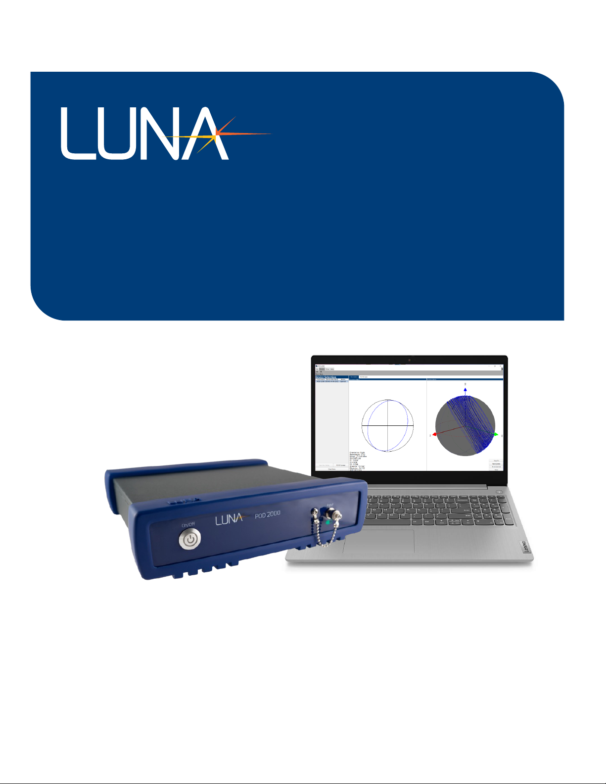
The Luna POD 2000 is an advanced polarimeter powered by digital signal processing (DSP). It is
specifically designed for high-speed polarization characterization, analysis, and monitoring of light
beams. With its four-channel configuration, this instrument can simultaneously acquire the four
Stokes parameters, allowing precise measurements of the instantaneous state of polarization (SOP)
and degree of polarization (DOP).
The POD 2000 features a USB 2.0 interface, enabling direct data transfer to a computer. This allows
users to conveniently access and process the measured data on a computer for further analysis. The
polarimeter supports a high sampling rate of up to 100 KS/s, ensuring accurate monitoring and
analysis of fast polarization changes in real time. Additionally, it provides a standard 100BASE-TX
Ethernet interface, allowing for measurement and control over a network.
The POD 2000 is equipped with a user-friendly interface that offers real-time graphic displays of the
polarization state. Two display options are available:
Poincaré Sphere Window: This window presents the polarization state as traces on a Poincaré
Sphere, providing a visual representation of how the SOP changes over time.
Oscilloscope Window: This window allows users to monitor polarization changes over time, akin to
observing waveforms on an oscilloscope. It offers a dynamic view of the polarization state,
facilitating the observation of temporal variations.
This document serves as a comprehensive guide for setting up and using the application software of
the POD 2000. For instructions on properly setting up the hardware, please refer to the POD 2000
Quick Start Guide.
Note: The POD 2000 Quick Start Guide provides detailed information on hardware setup, which
should be followed to ensure proper installation and operation
There are 2 configurations available:
POD 2000-15-FC/APC: POD 2000 1-port terminated high speed polarimeter, 1480 nm to 1640 nm,
with POD-2000 user interface software, FC/APC connector; POD 2000 main frame for S, C and L
band. Power cable, USB 2.0 A to B cable, USB drive for GUI and documents.
POD 2000-13-FC/APC: POD 2000 1-port terminated high speed polarimeter, 1240 nm to 1380 nm,
with POD-2000 user interface software, FC/APC connector; POD 2000 main frame for O band. Power
cable, USB 2.0 A to B cable, USB drive for GUI and documents.
POD 2000-10-FC/APC: (Coming) POD 2000 1-port terminated high speed polarimeter, 960 nm to
1160 nm, with POD-2000 user interface software, FC/APC connector; POD 2000 main frame for
960nm to 1160 nm. Power cable, USB 2.0 A to B cable, USB drive for GUI and documents.
POD 2000-35-FC/APC: (Coming) POD 2000 1-port terminated high speed polarimeter, 1240nm to
1380nm and 1480 nm to 1640 nm, with POD-2000 user interface software, FC/APC connector; POD
2000 main frame for S, C, L, and O band. Power cable, USB 2.0 A to B cable, USB drive for GUI and
documents.

POD 2000
DOC000000_POD 2000 User Manual Rev001
Page 9
4.
Hardware and Physical Setup
4.1.
Unpacking
Inspect the POD-201 for any physical damage resulting from shipping and transportation. If any
damage is found, please contact the carrier immediately. Additionally, carefully review the packing
list to verify if any parts or accessories are missing. This information is crucial for the user manual.
Packing List
Item #
Description
1
POD 2000
2
Power Cord
3
USB Cable
4
Ethernet Cable
6
USB key containing User Interface Installation Package, User Manual, Packing lists
4.2.
Communication Connection
4.2.1.
USB Communications
To communicate with the POD-2000 over an USB connection, connect a USB cable with a USB-B
male connector to the USB-B female connector on the back panel. The other end of the USB cable
must then be directly connected to the PC. The cable cannot be connected to an external USB hub
as it would performance issues when streaming measurement data to the PC.
4.2.2.
Ethernet Communications
To communicate with the POD-2000 over an Ethernet connection, connect a Cat-5e or greater cable
to the Ethernet female connector on the back panel (distinguished with the tab pointing down). Be
careful not to connect to one of the two LVDS female connectors (distinguished with the tab
pointing up).
The other end of the cable can then be connected to an Ethernet router that a host PC is also
connected to or be connected directly to a PC. When connected to an Ethernet router, the POD-
2000 will have the static IP address of 192.168.1.150 by default. Please refer to the SCPI commands
section, on how to change the IP address or enable dynamic IP addressing.
When connecting directly to a PC, one must set the IP address strategy to DHCP to allow the POD-
2000 to acquire a link-local IP address.
4.3.
Starting the system
To start the system, press the power button on the front panel. The power button will light. The
system is ready for the communication.
4.4.
Shutting the system down
To turn off the system, press and hold power button for about 0.5 second. If the system does not
begin to shut down, press and hold the power button for about 2 seconds to force the system to
turn off.

POD 2000
DOC000000_POD 2000 User Manual Rev001
Page 10
5.
Working Modes
5.1
Single Value Query
Single Value Query is the work mode of the POD-2000 upon power-on. To get data from the POD-
2000 in this work mode, one must send the SCPI query, :READ[:VALue]? (which can be
shortened to :READ?). The response to this query is a string consisting of an array of 5 integers
separated by commas. From left to right, the values are as follows: the S0 value, the S1 value, S2
value, the S3 value, and the light power value. The S0 value and light power values will always be
positive and the S1, S2, and S3 values can be either positive or negative. The light power value may
differ for a given intensity of light depending on the currently applied measurement unit for light
power.
By default, the response to the :READ? query will immediately be sent to the host as the POD-
2000 uses an internal automatic trigger source. However, the response can be deferred to a later
time if the trigger source of the POD-2000 is set to use an external TTL signal. If the trigger source is
an external TTL signal, the response to the query will only be sent upon the next time the TTL signal
goes high.
5.2
Continuous Stream
The Continuous Stream work mode automatically sends measurement data samples to the host
over the ancillary data port (i.e., endpoint 0x82 for USB connections and port 5026 for TCP/IP
connections) of the connection.
The timing of the data samples is determined by the trigger source and the downsample average
ratio. The downsample averaging process combines 1, 10, or 100 raw data samples into one
effective data sample. A higher downsample averaging ratio can reduce the noise in a set of data
samples at the cost of having a lower effective sampling rate. By default, the trigger source is an
internal automatic trigger, which means as soon as an effective data sample is generated it queued
up for transmission to the host. If the trigger source is instead an external TTL signal, then the
effective data sample will only be queued for transmission if the trigger signal went high prior to the
effective data sample being generated; otherwise, that data sample will be discarded.
Keep in mind that the absolute smallest timestep between any two data samples only goes down to
10 µs as the highest effective sampling rate is that of 100 kHz. Setting the trigger source to external
TTL and providing a signal with frequency higher than 100 kHz will not result in a faster sampling
rate.
6.
POD 2000 PC software
The Luna POD-2000 enables communication with a computer through Ethernet and USB and all
operations are centralized within the User. We provide a convenient software installation package
to ensure smooth software installation.
Let us take a tour of the application’s User Interface (UI). The tour will start with an introduction to
the UI layout, then further explains each UI components.

POD 2000
DOC000000_POD 2000 User Manual Rev001
Page 11
6.1.
Installation Package
6.1.1.
System Requirements
Minimum:
CPU: i3 5th Generation
RAM: 1 available Gigabyte
Recommended:
CPU: i5 11th Generation or better
GPU: Nvidia GeForce GTX 780 or better
RAM: 2 available Gigabytes or better
6.1.2.
Software Installation
To install the POD-2000 software, run the installer.
Specify the installation folder.
6.1.3.
Software Removal

POD 2000
DOC000000_POD 2000 User Manual Rev001
Page 12
To Uninstall the software, run the Uninstaller from the installation folder. Select Remove all
components and click next and uninstall to continue through the process.
6.2.
User interface overview
After starting the Luna Instruments desktop application, the application UI screen will appear on the PC
screen. The image below (Figure 1) is an illustration of a typical UI screen layout with all optional
displays turned on for a POD-2000 instrument.
The central section of the UI is the Main Page Area.
The upper section of the UI screen is for the display of the Menu Ribbon.
The left section of the UI screen is the optional Device Selection Area where the user can select the
current active device.
The right section of the UI is the optional Controls Area with more specific controls for the given page
loaded in the Main Page Area.
Each of the above UI components is further explained in the following titled sections, respectively.

POD 2000
DOC000000_POD 2000 User Manual Rev001
Page 13
Figure 1 UI Screen Layout
6.3.
Opening and Closing Devices
Device Selection is open by default when opening the application. Device Selection can be toggled
on/off from the View Tab in the Menu Ribbon.
6.3.1.
Setting the Active Device
Figure 2 Device Selection
Devices can be opened either via USB or TCP/IP Connection.
Menu Ribbon
Device Selection
Main Page
Controls

POD 2000
DOC000000_POD 2000 User Manual Rev001
Page 14
USB connected devices will automatically populate in the list and can be selected and opened
via the “Open New Device” button.
TCP/IP connected devices must be connected via the “TCP/IP Connect” button.
Figure 3 TCP/IP Connect Dialog Box
To complete the TCP/IP connection, enter the devices IP Address and click connect. If it
successfully connects, the device will then be listed in the Device Selection area.
6.3.2.
Closing Devices
Devices can be closed by selecting them in the Device Selection area and then pressing the “Close
Device” button.
6.4.
Measurement Data viewer
6.4.1.
Poincaré Sphere and Polarization parameters SOP
The Polarization screen displays both a 2D and 3D representation of real-time continuous streaming
data points from the POD-2000 in the form of the Polarization Ellipse and the Poincaré Sphere.
Figure 4 Polarization

POD 2000
DOC000000_POD 2000 User Manual Rev001
Page 15
The Polarization Ellipse shows the 2D Representation of the most recent point read from the POD-
2000. It also displayed current information in the bottom left corner. This data includes: Orientation,
Wavelength, Power, S0, S1, S2, S3, Azimuth Angle, Ellipticity, and the Degree of Polarization(DOP).
Furthermore, the Ellipse by default shows the cross section of the S1 and S2 axis, and can be
changed by selecting which Axis cross section the user wants by selecting them in the top right
corner of the Polarization Ellipse section.
The Poincaré Sphere is an interactable 3D view of the points read from the POD-2000. The view can
be rotated by holding down the right mouse button and moving the mouse. The view can also be
zoomed in/out by scrolling on the mouse wheel. Various controls have been placed on the bottom
right to control the view:
Trace On/Off: Turns on the point trace for the sphere, showing the path the points have taken.
Reset Camera: Resets the camera view of the sphere to its default location.
Reset (Control): Clears the data on the sphere
Pause/Continue: Pauses/Continues the updates to the sphere.
The Polarization Controls have two sections: Sphere View and Data Streaming.
The Sphere View controls allow for changing the rate at which points are added to the sphere. It
ranges from 1-60 points per seconds/minutes. It also shows the Duration of which the points on
the sphere represent.
The Data Streaming Controls allow for the user to save data as it streams from the POD-2000.
After selecting a file to save to, the user can designate a time frame between 1-10,000 seconds.
The User Interface will display how many points that translates to. Data Streaming will start
when the user presses the Start Button. Data Streaming can be paused and continued. If the
user decides to stop the data streaming early, the user can press the Cancel Button.

POD 2000
DOC000000_POD 2000 User Manual Rev001
Page 16
6.4.2.
Oscilloscope viewer and Polarization parameters
The Oscilloscope screen displays the data read from the POD-2000 over a short period of time.
Figure 5 Oscilloscope
The Oscilloscope has three main plots: Stokes Parameters, Angles, and DOP.
Each individual chart can be interacted with in these ways:
Zoom in/out X and Y Axis: Mouse Wheel
Zoom in/out X-Axis: Hold Right click and move up and down
Zoom in/out Y-Axis: Hold Right click and move left and right
Pan: Hold Left click and move up/down and/or left/right
The Oscilloscope Controls have two sections: Chart Controls and Data Streaming.
The Chart Controls allow for changing the X-Axis scale. This can be done by changing the value
manually or by resetting it to its default value (1). The user can also use the Clear Plots button to
clear all data from the Charts.
The Data Streaming Controls allow for the user to save data as it streams from the POD-2000.
After selecting a file to save to, the user can designate a time frame between 1-10,000 seconds.
The User Interface will display how many points that translates to. Data Streaming will start
when the user presses the Start Button. Data Streaming can be paused and continued. If the
user decides to stop the data streaming early, the user can press the Cancel Button.

POD 2000
DOC000000_POD 2000 User Manual Rev001
Page 17
6.4.3.
Long-Term data viewer
The Long-Term Oscilloscope screen displays the data read from the POD-2000 over a longer period
of time.
The Long-Term Oscilloscope has three main plots: Stokes Parameters, Angles, and DOP.
Each individual chart can be interacted with in these ways:
Zoom in/out X and Y Axis: Mouse Wheel
Zoom in/out X-Axis: Hold Right click and move up and down
Zoom in/out Y-Axis: Hold Right click and move left and right
Pan: Hold Left click and move up/down and/or left/right
The Oscilloscope Controls have two sections: Chart Controls and Data Streaming.
The Chart Controls has two functions.
Avg. Point Rate: Change the rate at which points are added to the oscilloscope.
Reset Scale: Reset the X-Axis scale to its current max value.
The Data Streaming Controls allow for the user to save data as it streams from the POD-2000.
After selecting a file to save to, the user can designate a time frame between 1-10,000 seconds.
The User Interface will display how many points that translates to. Data Streaming will start
when the user presses the Start Button. Data Streaming can be paused and continued. If the
user decides to stop the data streaming early, the user can press the Cancel Button.

POD 2000
DOC000000_POD 2000 User Manual Rev001
Page 18
6.5.
User interface menu and setup
6.5.1.
File Tab
The File Tab has two functions: Save and Load.
Save: Opens a File Dialog to pick a new or existing file and save the currently displayed data into
the designated CSV file.
Load: Opens a File Dialog to pick a previously saved file and load it into the displays of the
Polarization and Oscilloscope Pages.
6.5.2.
Device Tab
The Device Tab has two functions: Run and Stop.
Run: Initiates the data stream from the POD-2000 to the Desktop Application. This will start
displaying any incoming data to the GUI.
Stop: Stops the data stream from the POD-2000 to the Desktop Application. All Desktop
elements will not be updated due to the lack of incoming data, essentially pausing the screen.
6.5.3.
View Tab
The View Tab has two functions: Device Selection and Controls.
Device Selection: Opens the Device Selection Area
Controls: Opens the Controls Area for the current Page.
6.5.4.
Help Tab
The Help Tab has two functions: Help and About.
Help: Opens the Help Guide for the Luna Instruments Desktop Application.
Figure 6 Menu Ribbon
Figure 7 File Tab
Figure 9 View Tab
Figure 10 Help Tab
Figure 8 Device Tab

POD 2000
DOC000000_POD 2000 User Manual Rev001
Page 19
About: Opens the About Window contain details about the application itself.
6.5.5.
Settings
Figure 11 Settings
The Settings Menu opens by pressing the gear icon in the top right of the application. Any changes
made are not final until the Confirm button is pressed. Otherwise, if the gear icon or the Cancel
Button is pressed, all changes are discarded.
6.5.5.1.
Basic Settings
Figure 12 Basic Settings
The Basic Settings tab lets the user change the wavelength of the device. This option is only enabled
when there is a currently open device. The Work Mode Tab has three functions: Sampling Rate,
Trigger Output, and Pulse Width.
Wavelength: Changes the wavelength of the device.
Gain Level: Changes the Gain Level of the device between 1-5. Auto will automatically increase
or decrease the Gain Level to match the current input light power. Optimize will perform a one-
time automatic adjustment of the gain.
6.5.5.2.
Work Mode Settings
Figure 13 Work Mode Settings
The Work Mode Tab has three functions: Sampling Rate, Trigger Output, and Pulse Width.
Sampling Rate: Changes the sampling rate of the device between 1 kHz, 10kHz, and 100kHz.
Table of contents