Shure Incorporated
5/29
•
•
•
•
•
•
•
•
•
•
•
•
•
•
•
•
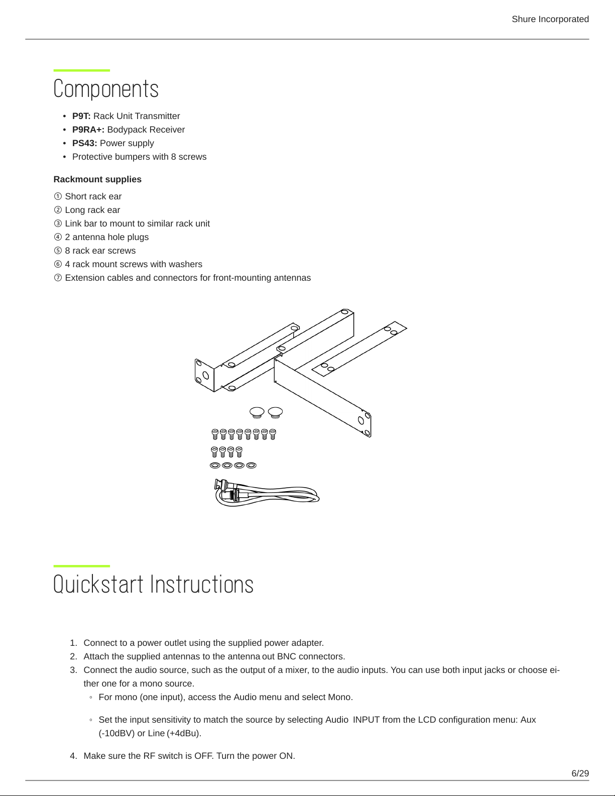
General Description
The Shure PSM 900 Wireless Personal Monitor System offers an unprecedented combination of superb audio quality, robust
RF performance, and category-leading features for the most demanding professional applications. Patented Audio Reference
Compandingandadvanceddigitalsignalprocessingtechnologyprovideexcellentstereoseparationandaudioclarity.Excep
tional transmitter linearity vastly reduces frequency intermodulation, allowing more channels per frequency band. Patented
CueMode technology enables the sound engineer to monitor different stage mixes with the touch of a button.
Features
Unparalleled Audio Quality
Bodypackreceiverswithadvanceddigitalsignalprocessingtechnologydelivermoreheadroom,improvedstereosepara
tion, and higher audio fidelity.
Patented Audio Reference Companding offers natural and transparent sound.
Available with Shure SE425 Sound Isolating earphonesfeaturingdualhighdefinitionMicroDriversforaccurateandbal
anced audio response.
Robust RF Performance
P9RA+ bodypack receivers offer enhanced signal reception and range.
Precision front-end RF filtering significantly reduces RF interference for a cleaner, stronger RF signal, fewer dropouts, and
fewer audible artifacts.
Exceptional transmitter linearity vastly reduces frequency intermodulation and allows up to 20 compatible channels per
frequency range.
Automatic RF gain control prevents signal distortion due to RF overload before it can affect performance.
Category-Leading Setup and Operation Features
CueMode allows monitoring of different stage mixes and storing of up to 20 separate channels on one bodypack for quick
and easy reference.
Front panel RF mute switch enables or disables RF transmission during setup.
Scan and Sync scans the RF environment with the bodypack and assigns an identified group and channel to your system
over wireless IR link.
MixMode technology allows the bodypack user to combine two separate audio channels for simultaneous listening in
both ears, or can transmit two independent IFB program feeds. Balance control on the bodypack adjusts the relative levels
for each audio signal.
Four-band parametric EQ gives the user the choice to adjust frequencies for a fully customized sound.
Advanced Rechargeability Options
The SB900B lithium-ion rechargeable battery provides extended usage times and precise tracking of remaining life and
charge cycle details.
TheSCB800USeightbaychargerbringsuptoeightSB900Bbatteriestofullchargewithintwohoursandhaschargesta
tus LEDs for each battery.
The SBC200 dual-docking charger works with SB900B, P3RA, P9RA+, P10R+, QLX-D Digital Wireless Systems, and
ULX-D Digital Wireless Systems, available with and without power supply.
The SBC220 networked dual-docking charger works with SB900B, PSM 300 (P3RA only), PSM 900 (P9RA+ only), PSM
1000 (P10R+ only), QLX-D Digital Wireless Systems, ULX-D Digital Wireless Systems, and Axient Digital (AD1 and AD2
only), available with and without power supply. When the SBC220 is connected to a network, battery information for each
transmitter can be viewed remotely.
®
™
®
®
®
®