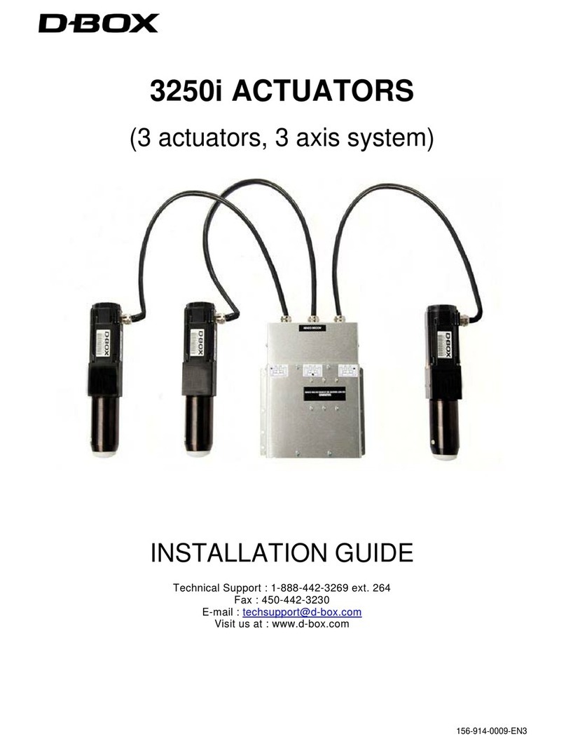
D-Box 2250i User manual

2 of 17
TABLE OF CONTENTS
Important Safety Instructions 3
1- D-BOX 2250i/2400i, 2 axis actuators system overview 4
2- D-BOX 2250i/2400i system dimensions and setup 4
3- Positioning the components 7
4- Positioning the actuators (Bottom view of seating) 8
5- Arm Rest mounting hole dimensions 9
6- Setting up the actuators in the seat 9
7- Connecting the actuators to the ACM (Actuator Control Module) 10
8- D-BOX 2250i/2400i Electrical diagram 11
9- Pictures of D-BOX 2250i/2400i installation 12
Appendix 1 - Installation of the ACM bracket 17
The 2250i/2400i may be installed in a single seat and loveseat only.
WARNING: DO NOT USE ANY ATTACHMENTS THATARE NOT RECOMMENDED BY THE
MANUFACTURER, AS THEY MAY CAUSE DAMAGE OR MALFUNCTIONS.

3 of 17
IMPORTANT SAFETY INSTRUCTIONS
1. Read these instructions.
2. Keep these instructions.
3. Heed all warnings.
4. Follow all instructions.
5. Do not use this apparatus near water.
6. Clean only with dry cloth.
7. Do not block any ventilation openings. Install in accordance with the manufacturer's instructions.
8. Do not install near any heat sources such as radiators, heat registers, stoves, or other apparatus
(including amplifiers) that produce heat.
9. Do not defeat the safety purpose of the polarized or grounding-type plug. A polarized plug has two
blades with one wider than the other. A grounding type plug has two blades and a third grounding
prong. The wide blade or the third prong are provided for your safety. If the provided plug does not fit
into your outlet, consult an electrician for replacement of the obsolete outlet.
10. Protect the power cord from being walked on or pinched particularly at plugs, convenience receptacles,
and the point where they exit from the apparatus.
11. Only use attachments/accessories specified by the manufacturer.
12. Use only with the cart, stand, tripod, bracket, or table specified by the manufacturer, or sold with the
apparatus. When a cart is used, use caution when moving the cart/apparatus combination to avoid
injury from tip-over.
13. Unplug this apparatus during lightning storms or when unused for long periods of time.
14. Refer all servicing to qualified service personnel. Servicing is required when the apparatus has been
damaged in any way, such as power-supply cord or plug is damaged, liquid has been spilled or objects
have fallen into the apparatus, the apparatus has been exposed to rain or moisture, does not operate
normally, or has been dropped.
15. Do not expose this apparatus to dripping or splashing and ensure that no objects filled with liquids, such
as vases, are placed on the apparatus.
16. To completely disconnect this apparatus from the AC Mains, disconnect the power supply cord plug
from the AC receptacle.
17. The mains plug of the power supply cord shall remain readily operable.
18. Do not expose batteries to excessive heat such as sunshine, fire or the like.
The lightning flash with arrowhead symbol within an equilateral
triangle is intended to alert the user to the presence of uninsulated
"dangerous voltage" within the product's enclosure that may be of
sufficient magnitude to constitute a risk of electric shock to
persons.
The exclamation point within an equilateral triangle is intended to
alert the user to the presence of important operating and
maintenance (servicing) instructions in the literature accompanying
the product.
This symbol indicates that you must communicate with the
manufacturer for disposal of the equipment.
WARNING: To reduce the risk of fire or electric shock, do not expose this apparatus to rain or moisture.

4 of 17
The D-BOX 2250i/2400i actuators system is designed to be installed into the armrest of qualified
home theater seating.
1- D-BOX 2250i/2400i, 2 axis actuators system overview
When properly installed the system will give you a two (2) axis motion simulator designed for
home entertainment. The seat will move you front to back and side to side. Only the rear of the
seat will move since there is a pivot point in the front. In order for the seat to be able to stand the
motion and be supported by a single front pivot, it is important that the structure be well built.
We suggest seat manufacturer to reinforce the seat by making a single piece wood panel on the
back,supporting the armrests or by adding a steel bar that will join the two side armrest together.
The front reinforcement part can also be made of hard wood or steel. See pictures at the end of
this document for more details.
Each actuator has a piston that will go in and out of the cylinder to make the motion. At the end of
each piston there is a hard plastic pivot piece that will be in contact with the floor (or a floor
protector and anti-slip cup). Under each cup there is a rubber pad to protect the floor and also to
make sure that the seat will stay in place during a movie or a game.
2- D-BOX 2250i/2400i system dimensions and setup
Caution:
When removing the actuators from the packaging box, be careful not to bend the metal
plate holding the two actuator cable connectors. Also, be careful not to pull on the two
connectors. One connector powers the motor (3 pins white connector) while the other carries the
optical encoder signals.

5 of 17
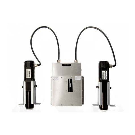
The D-BOX 2250i/2400i, 2 axis motion system consists of:
Description Quantity
ACM unit (Actuator Control Module) 1
Actuator (max. capacity 250 lbs each 2250i and 400 lbs each 2400i) 2
Power Cable, 6 feet (000-090-0010-Z00) 1
Single Cup, Aluminum (810-0002) 3
Screw, Bolt, Hex, Cap, 1/4-20 X 3/4, Black (100-0551) 12
Washer, Lock, 1/4, Black (102-0051) 12
Included with the L bracket option – 2 Actuators (#801-0007)
Washer, Lock, tooth, 1/4, Zn (102-0053) 8
Screw, Bolt, Hex, Cap, 1/4-20 X 1, Black (000-100-0555-Z00) 8
Tiewrap, 7 3/8" (190-0014) 4
CAT5 cable, 10 feet (000-090-0011-Z00) 1
L bracket 4
Clamp, Cable, 3/8” (094-0007) 1
Clamp, Cable, ½” black (094-0012) 6
Plate, Plastic, Adhesive, Tiewrap (Tiewrap) (190-0007) 1
ACM bracket 1
Required Tools
3/8 inch drive ratchet
3/8 inch drive 7/16 inch socket
Phillips screwdriver / electric screwdriver
Wire cutters

6 of 17
We suggest that the ACM unit be mounted on the back wood panel of the seat as the
connections to each actuator will be easier and because each actuator is supplied with a 51”
cable. Below you will find the dimensions of the 2250i/2400i actuators and the ACM unit.
D-BOX 2250i/2400i actuators dimensions (.75” to 2.25” Bracket)
ACM (Actuator Control Module) dimensions

7 of 17
The D-BOX 2250i/2400i actuators system have been designed to be installed into armrest of
qualified home theater seating. Each Actuator must be inserted into the armrest hole especially
made for that purpose. Please see drawing below. Also refer to armrest hole specifications in the
present document.
3- Positioning the components

8 of 17
Each actuator should be mounted at the bottom rear end of each armrest. For that purpose an
actuator mounting hole and an actuator cable access hole should be provided. See drawing
below for more details;
4- Positioning the actuators (Bottom view of seating)
Typical Dual Recliner with middle armrest Installation (bottom view)

9 of 17
In the drawings below you will find the dimensions of the hole needed to mount the actuator and
be able to screw it in place using four (4) 1/4-20 screws. You will also find the dimensions of the
cutout hole for the actuator’s cable assembly.
5- Arm Rest mounting hole dimensions
Actuator cutout hole Actuator cable assembly hole
Before making the connections between each ACM unit and its associated pair of actuators, you
should insert and screw down one actuator in each armrest and run the cable through the
actuator cable access hole (opening in the front of the actuator). When the actuators are properly
secured using four (4) 1/4-20 screws and a lock washer, you can connect the cable into the ACM
unit.
6- Setting up the actuators in the seat
Note: be careful not to damage the connectors or the aluminum plate at the end of the actuator’s
cable.

10 of 17
7- Connecting the actuators to the ACM (Actuator Control Module)
IMPORTANT NOTICE
A. The connections between the ACM and the actuators must be done correctly in order for the
system to work properly. The exact position of each actuator in regards to the seat is indicated on
a sticker located on the top of the ACM unit. This sticker indicates if it is a left or right actuator.
See drawing below for more details;
: Before doing any connection into the ACM unit make sure there is no
power by detaching the A/C cord. There is high voltage inside the ACM unit, and only service
qualified technician are allowed to do the connections.
B. In order to connect each actuator into the ACM unit, you need to take the ACCESS COVER
off by removing the Philipps screws holding it in place and lifting it gently toward the back. You
also need to locate all of the Philipps screws (10) that are included in the package.
Removing ACM’s access cover
C. Pass the cable assembly of each motor through the proper ACM housing hole (making sure
the actuator is at the proper position in regards to the sticker) and secure the metal door using
two (2) Philipps screws supplied in the package (start by the two (2) screws at the bottom of the
metal door). See drawing below;
Making connections into the ACM unit

11 of 17
D. After both actuator’s metal doors have been properly secured to the housing, connect the
motor and the encoder connector of both actuators (as shown in drawing below). You should
hear a click when the connector is fully inserted. Finally, assemble and secure the access cover,
there is one (1) screw on each side and two (2) screws on the rear. Note that the screws
attaching the rear cover passes through the actuator metal door.
8- D-BOX 2250i/2400i Electrical diagramm
Note: Each time you will power-up the motion seat you will hear the motors locking themselves
up. This usually takes a few seconds unless the piston of either actuator has not been pulled in
completely at the last shutdown.

12 of 17
When you have finished installing the actuators and the ACM in the seat, make sure that all the cables
(motor cables, power cables and Cat-5 cables) are properly secured. Also make sure that none of the cables
can rub against a moving part (such as the reclining mechanism) because it may damage the insulation and
make the product unsafe for use.
9- Pictures of D-BOX 2250i/2400i installation (in a loveseat)

13 of 17
Pictures of D-BOX 2250i/2400i installation (in a loveseat)
NOTE: Cables must be positioned so they won’t interfere with the recliner’s mechanism.

14 of 17
Pictures of D-BOX 2250i/2400i installation (in a loveseat)
NOTE: Cables must be positioned so they won’t interfere with the recliner’s mechanism.

15 of 17
Pictures of D-BOX 2250i/2400i installation (in a single electrical reclining seat)
NOTE: Cables must be positioned so they won’t interfere with the recliner’s mechanism.

16 of 17
Pictures of D-BOX 2250i/2400i installation (in a single electrical reclining seat)

17 of 17
Appendix 1
Installation of the ACM bracket
This manual suits for next models
1
Table of contents
Other D-Box Controllers manuals
Popular Controllers manuals by other brands
micro-trak
micro-trak MT-2400 LR Reference manual

Vega
Vega VEGAMET 841 operating instructions
THEORY
THEORY DLC-250.4 Installation and programming guide
WEISS
WEISS ER12D-1 Installation & operation instructions
Danfoss
Danfoss ECL Comfort 296 operating guide
WAREMA
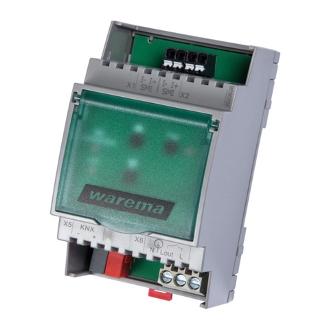
WAREMA KNX SA 16M230 SMI REG installation instructions

