Lennox @DNOVA 2mAC ADVANCED CONTROLLER User manual
Other Lennox Controllers manuals
Lennox
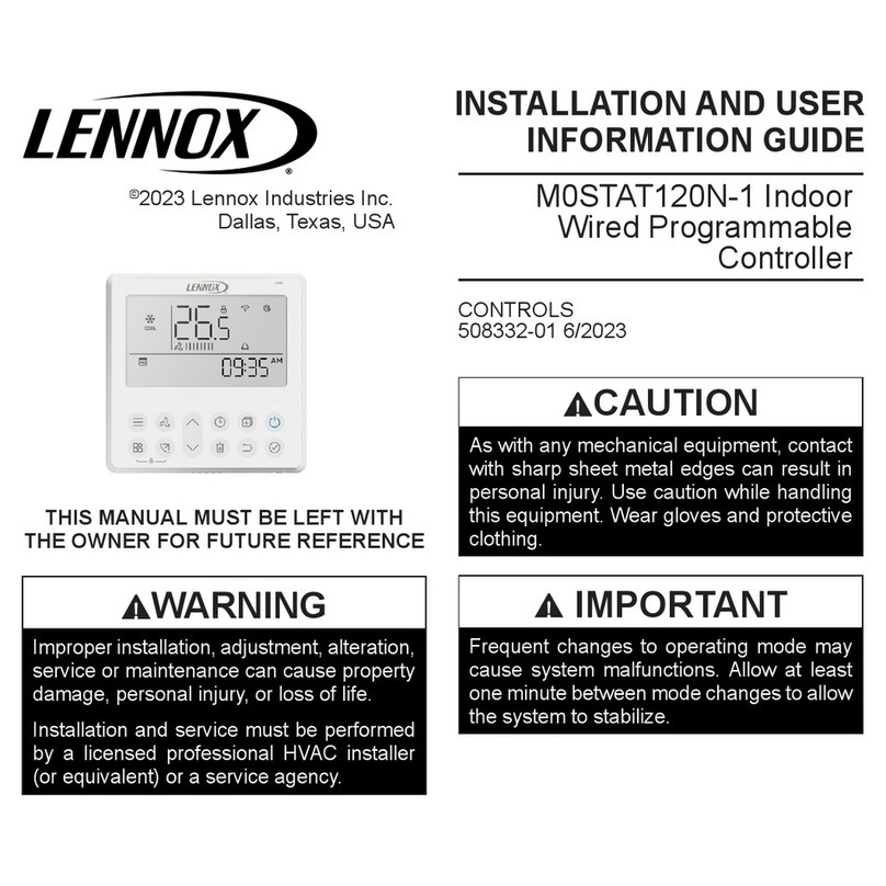
Lennox M0STAT120N-1 User manual
Lennox
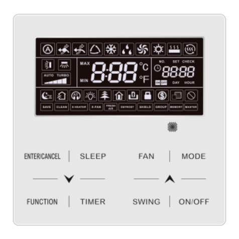
Lennox VRF VEWCL1B User manual

Lennox
Lennox E210 Instruction manual

Lennox
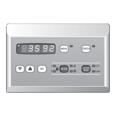
Lennox V0STAT52 User manual
Lennox
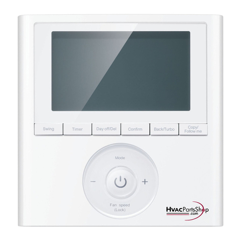
Lennox HYDRON Series Instruction manual
Lennox
Lennox M0STAT64Q-2 Installation instructions
Lennox
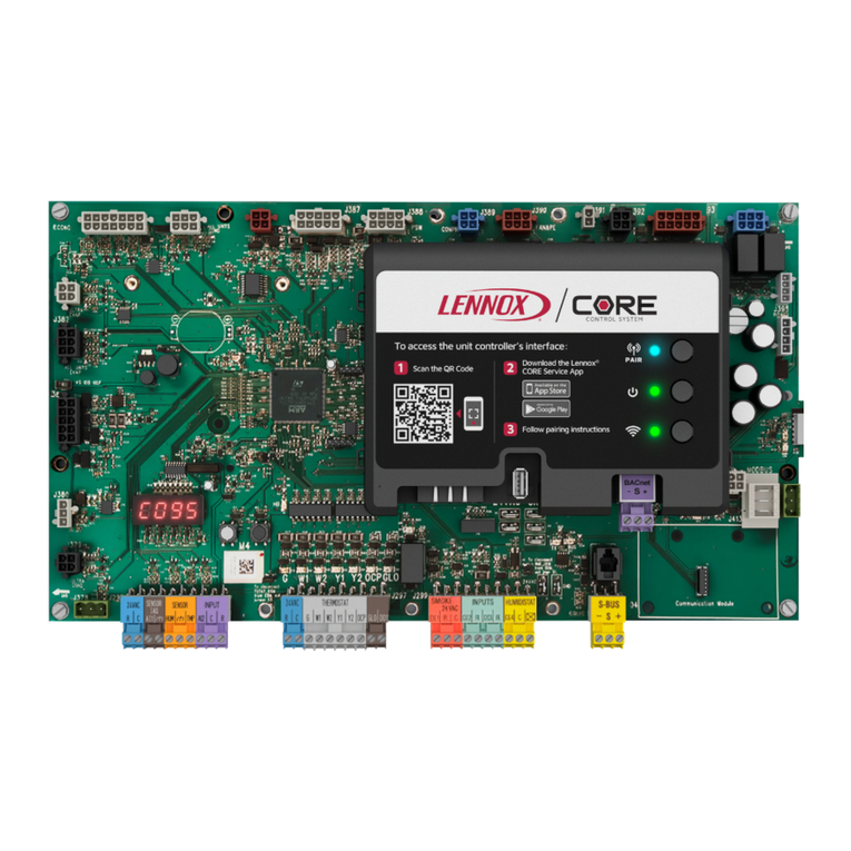
Lennox Core Unit Controller User manual
Lennox
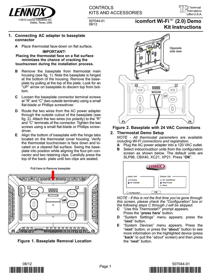
Lennox icomfort Wi-Fi (2.0) Demo User manual
Lennox
Lennox F1943L-3P User manual
Lennox
Lennox CLIMATIC 200 User manual
Lennox
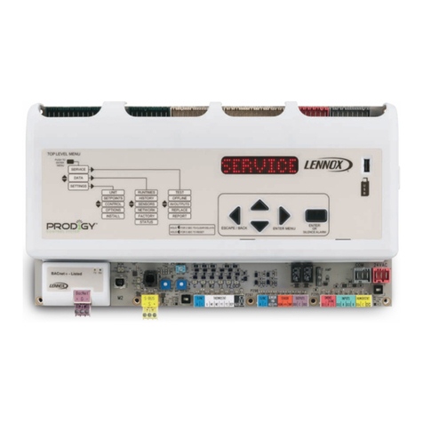
Lennox Prodigy User manual
Lennox
Lennox @DNOVA pCO1 User manual
Lennox
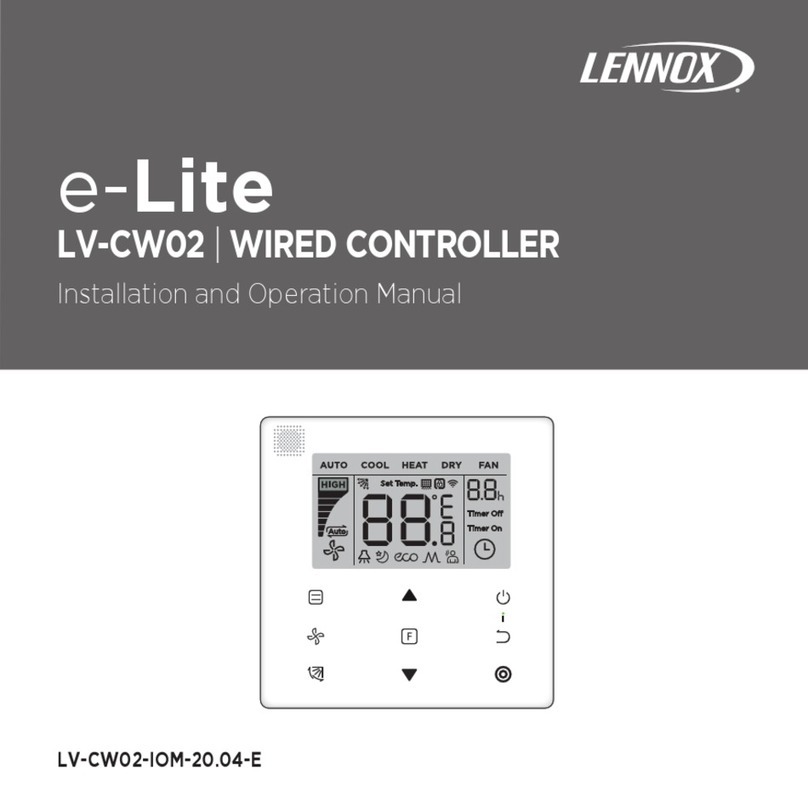
Lennox e-Lite LV-CW02 User manual
Lennox
Lennox V0STAT51P-2 User manual
Lennox
Lennox VRF VEWCL1E User manual

Lennox
Lennox 22U50 User manual
Lennox
Lennox HYDROCONTROL User manual
Lennox
Lennox M0STAT60Q-1 User manual
Lennox
Lennox LXTFF01M User manual
Lennox
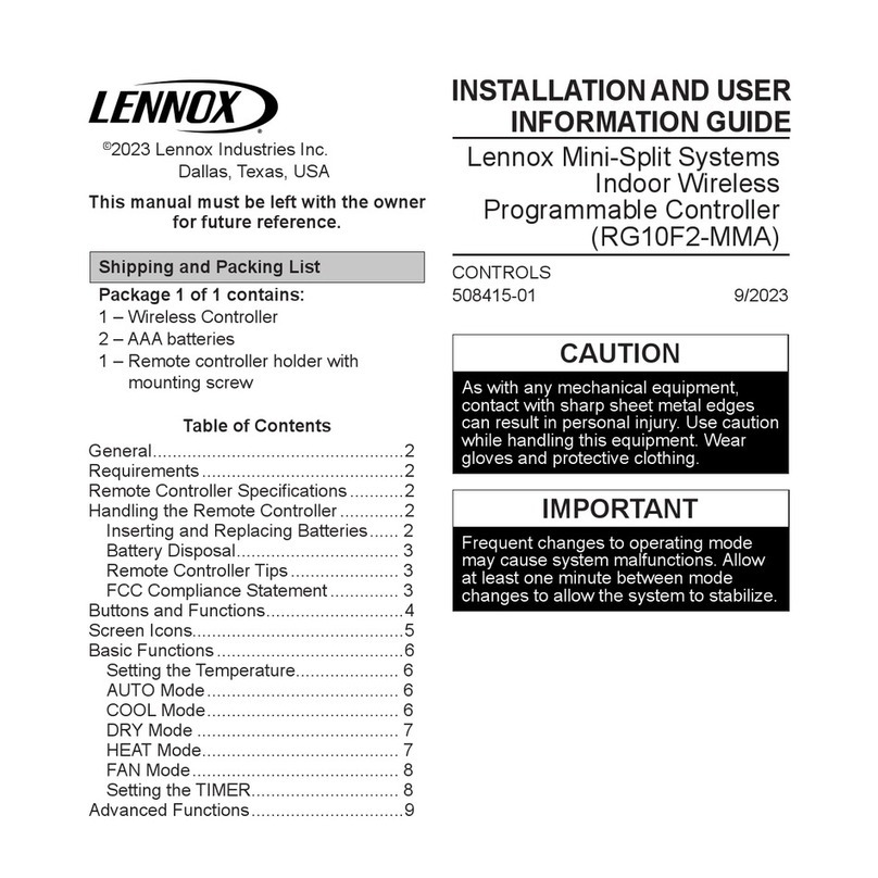
Lennox RG10F2-MMA User manual
Popular Controllers manuals by other brands

Digiplex
Digiplex DGP-848 Programming guide

YASKAWA
YASKAWA SGM series user manual

Sinope
Sinope Calypso RM3500ZB installation guide

Isimet
Isimet DLA Series Style 2 Installation, Operations, Start-up and Maintenance Instructions

LSIS
LSIS sv-ip5a user manual

Airflow
Airflow Uno hab Installation and operating instructions
