D-Link DCS-9200T User manual

Additional documentation is also available on the D-Link website
DCS-9200T
Quick Installation Guide
Group Temperature Screening Camera Kit

Contents
English 1

DCS-9200T Quick Installation Guide 1
ENGLISH
Before You Begin
This installation guide provides instructions for installing the DCS-9200T on your network. Additional
documentation is also available on the D-Link support website.
•DCS-9200T User Manual: For additional information and instructions on how to configure the
device using the web user interface.
Package Contents
This DCS-9200T package includes the following items:
•DCS-9210T Thermal Camera and wall mount
•Blackbody Calibrator and wall mount
•Network Video Recorder
•2x Tripods
•Quick Start Guide
Additional optional accessories are also available, please contact your local D-Link reseller for more
information.
If any of the above items are damaged or missing, please contact your local D-Link reseller.
System Requirements
•Windows® operating system
•Internet Explorer 11 or later (for configuration)
Hardware Overview

2DCS-9200T Quick Installation Guide
ENGLISH
Interface Connectors
1
2
3
4
5
6
7
8
9
# Cable Core Description
1RS485 Connects to external pan and tilt
2ALARM IN2 Connects to an alarm device
3ALARM OUT2
4ALARM IN1
5ALARM OUT1
6Audio Input Connect to microphone
7Audio Output Connect to speaker
8DC12 V Power interface, connects to the 12 V DC power adapter
9Network Interface Connects to a standard RJ45 Ethernet cable

DCS-9200T Quick Installation Guide 3
ENGLISH
Installation
The recommended installation environment is in an airless windless aisle. Please ensure the monitoring
field is far away from any objects that could produce airflow, high temperature or reflection; e.g. a car.
Please do not install opposite of a door, air conditioner or any place where the sun is directly shining.
To ensure temperature measurement accuracy, please install the camera indoors or in a controlled
environment. The measurement might deviate from the actual temperature if the camera is installed
in an open-air environment.
In any installation configuration, the optimal height of the camera is 2-2.3 m from the ground. For optimal
results, the blackbody should be the same height as the camera and 3-5 meters away.
Wall Mount Conguration
3 - 5 m
2 - 2.3 m
3 m5 m
2 - 2.3 m
3 m
3 m4 m
5 m
1. If mounting on the wall, the DCS-9200T should be installed anywhere from 2-2.3 m from the ground.
2. The Blackbody should be installed at the same height as the camera, but 3-5 m in front of
the camera, inside the eld of view (FOV) of the camera. The optimal distance to measure
temperature is at the same distance as the blackbody is installed.

4DCS-9200T Quick Installation Guide
ENGLISH
Ceiling Mount Conguration (Optional)
3 - 5 m (4 m recommended)
2 - 2.3 m
2 - 2.3 m
3 m5 m
2 - 2.3 m2 - 2.3 m
3 - 5 m (4 m recommended)
3 m5 m 3 m4 m
1. If mounting from the ceiling, the DCS-9200T should be installed anywhere from 2-2.3 m from the
ground.
2. The Blackbody should be installed at the same height as the camera, but 3-5 m from the camera,
inside the eld of view (FOV) of the camera. The optimal distance to measure temperature is at
the same distance as the blackbody is installed.

DCS-9200T Quick Installation Guide 5
ENGLISH
Web Management Interface (WMI)
You must use Internet Explorer 11 or later to access the web management system; otherwise some
functions may be unavailable.
Logging Into the System
1. Open Internet Explorer.
2. Enter the IP address of the camera (default IP address: 192.168.0.121) in the address box, and
press Enter.
3. After the login page is displayed, input the user name and password. The default name and
password are both admin.
4. You are prompted to modify the password after you log into the system for the first time.
5. You may change the system display language on the login page to a language of your choice.
6. Click Login. The homepage will be displayed.
Logging Out of the System
1. To logout of system, click the logout icon in the upper right corner of the homepage.
2. The login page will be displayed after you logout of the system.
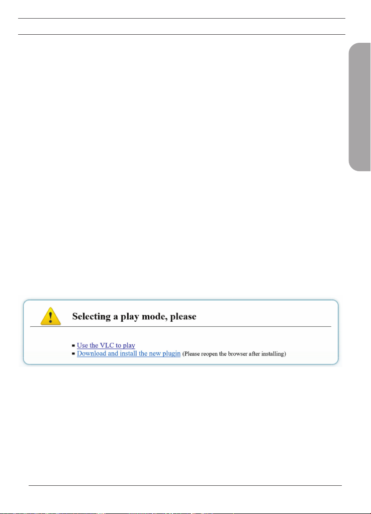
Plugin Installation
1. If this is your first time using the Web Management Interface, you must first download the latest
plugin. If the latest plugin is not corretly installed, you will not be able to configure parameters,
even if you can view video playback.
2. Before installing the plugin, it is recommended to temporarily exit any anti-virus software and
close your internet browser.

6DCS-9200T Quick Installation Guide
ENGLISH
Temperature Management
1. Navigate to Conguration > Temperature Measurement.
2. There are 3 main configuration sections that need to be modified; Parameter Configure, Thermal
Mapping, and Thermal Calibration.
Thermal Calibration
Note: It necessary to configure these settings when using the Blackbody.
1. Set Enable and Display Area Info to On to enable Thermal Calibration.
2. The Target Temperature should be set to the LED value displayed on the back of the Blackbody as
seen above. 40 °C is recommended.
3. Emission Rate is the thermal radiation emissivity of the Blackbody. The default value is 0.98.
4. Distance is the distance from the Blackbody to the thermal camera.
5. Using the mouse, drag a square over where the Blackbody is located on the screen, as seen in the
above image. Note: Be sure that the green square exactly outlines the Blackbody for the most
accurate results.
6. Click Apply to save settings.

DCS-9200T Quick Installation Guide 7
ENGLISH
Thermal Mapping
1. Thermal Mapping overlays the visible and thermal videos to synchronize the data coming from
the two separate lenses, corresponding to how accurate the temperature detection results will be.
2. The goal of Thermal Mapping is to have the green square on the visible camera view match up with
the green square on the thermal camera view that was set in thermal calibration.
3. Use zoom and focus controls found in the red box above to best match the zoom of the thermal
camera view on the right side.
4. Select a Mapping Point. There are three possible points. The more points you calibrate the more
accurate your mapping will be. Match the same color points on the thermal camera view to the
visible camera view.
5. The green box will calibrate itself on the visible camera view based on the Mapping Points on both
thermal and visible camera views.
Note: The closer the green square is to exactly outlining the Blackbody, the more accurate your results
will be.

8DCS-9200T Quick Installation Guide
ENGLISH
Face Detection
1. Under Temperature Measurement, navigate to Parameter Congure.
2. Enable Face Detection and Show Detection Area.
3. Area ID is the number of detection areas. Generally, we only need to set one detection area but
we can optionally set up to 8. For each area, click points on the image to draw a frame over the
target observation area.
4. Face Pixel Min, Face Pixel Max and Image Matting Quality refer to the quality of the face image that
is saved after it is detected. All three can be adjusted according to your systems requirements.
5. Leave other options at their default values.
6. Refer to the User Manual for more detailed information on each configuration setting.
7. Click Apply to save settings.
Temperature Parameters
1. Set Enable to On to enable temperature detection.
2. Swap between Celcius and Fahrenheight under Temperate Unit. Celsius is set as default.
3. Set the Ambient Temperature to the temperature of the camera’s environment; e.g. indoor
temperature of 25 °C.
Table of contents
Other D-Link Camera Accessories manuals
Popular Camera Accessories manuals by other brands

Viltrox
Viltrox EF-NEX Mount instructions

Calumet
Calumet 7100 Series CK7114 operating instructions

Ropox
Ropox 4Single Series User manual and installation instructions

Cambo
Cambo Wide DS Digital Series Main operating instructions

Samsung
Samsung SHG-120 Specification sheet

Ryobi
Ryobi BPL-1820 Owner's operating manual


