manuals.online logo
Brands
  1. Home
  2. •
  3. Brands
  4. •
  5. D-Link
  6. •
  7. Switch
  8. •
  9. D-Link EasySmart DGS-1100-05 User manual

D-Link EasySmart DGS-1100-05 User manual

Other manuals for EasySmart DGS-1100-05

1

This manual suits for next models

3

Other D-Link Switch manuals

D-Link DES-1226G User manual

D-Link

D-Link DES-1226G User manual

D-Link DGS-1228P User manual

D-Link

D-Link DGS-1228P User manual

D-Link 3100 24P - DGS Switch - Stackable User manual

D-Link

D-Link 3100 24P - DGS Switch - Stackable User manual

D-Link DKVM-4K - KVM Switch User manual

D-Link

D-Link DKVM-4K - KVM Switch User manual

D-Link DMS-1250 Series Manual

D-Link

D-Link DMS-1250 Series Manual

D-Link RG-S8614 Installation and operating manual

D-Link

D-Link RG-S8614 Installation and operating manual

D-Link DGS-3312SR User manual

D-Link

D-Link DGS-3312SR User manual

D-Link DES-1008F User manual

D-Link

D-Link DES-1008F User manual

D-Link DHP-540 User manual

D-Link

D-Link DHP-540 User manual

D-Link DES-7000 Series User manual

D-Link

D-Link DES-7000 Series User manual

D-Link DGS-3324SR User manual

D-Link

D-Link DGS-3324SR User manual

D-Link DES-1005E User manual

D-Link

D-Link DES-1005E User manual

D-Link DES-3250TG User manual

D-Link

D-Link DES-3250TG User manual

D-Link DGS-1210-10 User manual

D-Link

D-Link DGS-1210-10 User manual

D-Link DHP-346AV User manual

D-Link

D-Link DHP-346AV User manual

D-Link DGS-3130-54TS User manual

D-Link

D-Link DGS-3130-54TS User manual

D-Link DXS-3227P - xStack Switch - Stackable User manual

D-Link

D-Link DXS-3227P - xStack Switch - Stackable User manual

D-Link DES-3326SRM User manual

D-Link

D-Link DES-3326SRM User manual

D-Link DES-3010FA User manual

D-Link

D-Link DES-3010FA User manual

D-Link DKVM-4U User manual

D-Link

D-Link DKVM-4U User manual

D-Link DGS-2205 - Desktop Switch User manual

D-Link

D-Link DGS-2205 - Desktop Switch User manual

D-Link DGS-1052 User manual

D-Link

D-Link DGS-1052 User manual

D-Link DES-1050G User manual

D-Link

D-Link DES-1050G User manual

D-Link DGS-1510 Series User manual

D-Link

D-Link DGS-1510 Series User manual

Popular Switch manuals by other brands

SMC Networks SMC6224M Technical specifications

SMC Networks

SMC Networks SMC6224M Technical specifications

Aeotec ZWA003-S operating manual

Aeotec

Aeotec ZWA003-S operating manual

TRENDnet TK-209i Quick installation guide

TRENDnet

TRENDnet TK-209i Quick installation guide

Planet FGSW-2022VHP user manual

Planet

Planet FGSW-2022VHP user manual

Avocent AutoView 2000  AV2000BC AV2000BC Installer/user guide

Avocent

Avocent AutoView 2000 AV2000BC AV2000BC Installer/user guide

Moxa Technologies PT-7728 Series user manual

Moxa Technologies

Moxa Technologies PT-7728 Series user manual

Intos Electronic inLine 35392I operating instructions

Intos Electronic

Intos Electronic inLine 35392I operating instructions

Cisco Catalyst 3560-X-24T Technical specifications

Cisco

Cisco Catalyst 3560-X-24T Technical specifications

Asante IntraCore IC3648 Specifications

Asante

Asante IntraCore IC3648 Specifications

Siemens SIRIUS 3SE7310-1AE Series Original operating instructions

Siemens

Siemens SIRIUS 3SE7310-1AE Series Original operating instructions

Edge-Core DCS520 quick start guide

Edge-Core

Edge-Core DCS520 quick start guide

RGBLE S00203 user manual

RGBLE

RGBLE S00203 user manual

Thrustmaster FLIGHT SIMULATOR X quick guide

Thrustmaster

Thrustmaster FLIGHT SIMULATOR X quick guide

Southwire SURGE GUARD 41390 RVC troubleshooting guide

Southwire

Southwire SURGE GUARD 41390 RVC troubleshooting guide

Buhler Nivotemp NT 61 Brief instructions

Buhler

Buhler Nivotemp NT 61 Brief instructions

Kramer VS-41HDCP user manual

Kramer

Kramer VS-41HDCP user manual

Techly IDATA AU-270 user manual

Techly

Techly IDATA AU-270 user manual

Belkin F1U109 user manual

Belkin

Belkin F1U109 user manual

manuals.online logo
manuals.online logoBrands
  • About & Mission
  • Contact us
  • Privacy Policy
  • Terms and Conditions

Copyright 2025 Manuals.Online. All Rights Reserved.

1Product Introduction D-Link Smart Managed Switch User Manual
2
1 Product Introduction
Thank you and congratulations on the purchase of your new D-Link Smart Managed Switch.
D-Link's next generation Smart Managed switch series blends plug-and-play simplicity with exceptional
value and reliability for small and medium-sized business (SMB) networking. All models are housed in a
robust metal case with easy-to-view front panel diagnostic LEDs.
Flexible Port Configurations. The DGS-1100 series is the new generation of Smart Managed Switches,
featuring 5 to 8 10/100/1000 Mbps.
D-Link Green Technology. The DGS-1100 Series features D-Link Green Technology which helps
conserve power without sacrificing operational performance. Using IEEE 802.3az Energy Efficient Ethernet
(EEE), the DGS-1100 Series saves power by automatically putting inactive ports into a sleep mode.
Extensive Layer 2 Features. Designed as comprehensive L2 devices, these switches support a variety of
functions such as FDB, VLAN, Spanning Tree, and Loopback Detection to enhance performance and
network resilience.
Traffic Segmentation and QoS.The switches support 802.1Q VLAN standard tagging to enhance network
security and performance. The switches also support 802.1p priority queues, enabling users to run
bandwidth-sensitive applications such as streaming multimedia by prioritizing that traffic in network. The
Surveillance VLAN will place the video traffic from pre-defined IP surveillance devices to an assigned VLAN
with higher priority, so it can be separated from normal data traffic.
Network Security. Storm Control can help to keep the network from being overwhelmed by abnormal
traffic. Meanwhile, Port Security provides administrators with an additional layer of security to prevent
unauthorized users from accessing the network.
Versatile Management. The DGS-1100-05/05PD/08/08PD feature an intuitive, web-based management
interface that allows administrators to remotely control their network down to the port level. The D-Link
Network Assistant (DNA) easily allows administrators to discover multiple D-Link Smart Managed Switches
within the same L2 network segment and display them on-screen for instant access. With this utility, users
do not need to change the IP address of their PC. This allows for simultaneous configuration and basic
setup of all discovered devices, including password changes and firmware upgrades.
DGS-1100-05
5-Port 10/100/1000Mbps Smart Managed Switch.
Front Panel
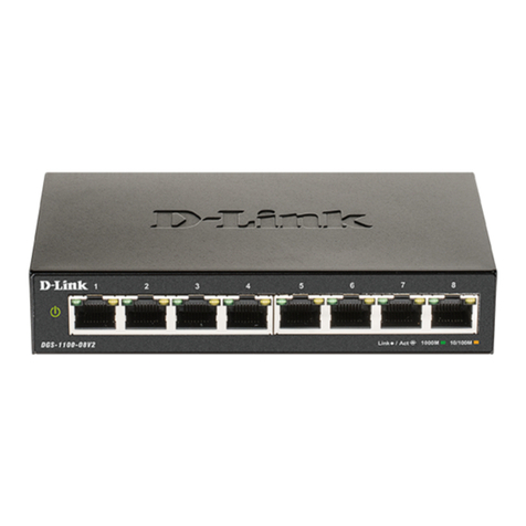
Figure 1.1 – DGS-1100-05 Front Panel
Power LED: The Power LED lights up when the Switch is connected to a power source.
Link/Act/Speed LED (Ports 1-5): 10/100/1000 Mbps ports to connect Ethernet devices to the switch.
1 Product Introduction D-Link Smart Managed Switch User Manual
3
3
Rear Panel
Figure 1.2 – DGS-1100-05 Rear Panel
Power: Input for a 5V/1A AC adapter.
Reset: Press the Reset button for 1 to 5 seconds to reboot the Switch. Press the Reset button for 6 to10
seconds to reset the Switch back to the default settings. The LED will light up solid amber for 2 seconds.
When pressing the Reset button for longer than 10 seconds, the device will enter loader mode and the LED
will light up solid green for 2 seconds. If the device cannot reboot, it will automatically enter loader mode.
Alternatively, you can press Reset to power up the device and enter loader mode.
Kensington Lock: This is used to attach a physical Kensington security lock.
GND: This is used to connect the Switch to ground.
DGS-1100-05PD
2-Port 10/100/1000Mbps PoE and 3-Port 10/100/1000Mbps with 1 PD port Smart Managed Switch.
Front Panel
Figure 1.3 – DGS-1100-05PD Front Panel
Power LED: The Power LED lights up when the Switch is connected to a power source. If the Power LED is
Blinking, PoE Pass Through is Off.
Link/Act/Speed LED (Ports 1-5):
Flashing: Indicates a network link through the corresponding port.
Blinking: Indicates that the Switch is either sending or receiving data to the port.
Green: Indicates that the port is running at 1000M.
Amber: Indicates that the port is running at 10/100M.
Light off: No link.
PoE PSE LED (Port 1-2):
Solid Green: PD device insert and power feeding.
Solid Amber: PD device insert but failure occurs.
Light off: No PD device insert.
PoE PD (Port 5):
Solid Green: Receiving power from PSE per 802.3at.
Solid Amber: Receiving power from PSE per PSE.
Light off: No link.
Reset: Press the Reset button for 1 to 5 seconds to reboot the Switch. Press the Reset button for 6 to10
seconds to reset the Switch back to the default settings. The LED will light up solid amber for 2 seconds.
When pressing the Reset button for longer than 10 seconds, the device will enter loader mode and the LED
will light up solid green for 2 seconds. If the device cannot reboot, it will automatically enter loader mode.
Alternatively, you can press Reset to power up the device and enter loader mode.
1Product Introduction D-Link Smart Managed Switch User Manual
4
Rear Panel
Figure 1.4 – DGS-1100-05PD Rear Panel
Power: Use RJ45 to connect the PD port (port 5) and Power over Ethernet Adapter Kit.
Kensington Lock: This is used to attach a physical Kensington security lock.
GND: This is used to connect the Switch to ground.
NOTE: The power budget is 18 Watts with 802.3at and 8 Watts with
802.3af for DGS-1100-05PD.
DGS-1100-08
8-Port 10/100/1000Mbps Smart Managed Switch.
Front Panel
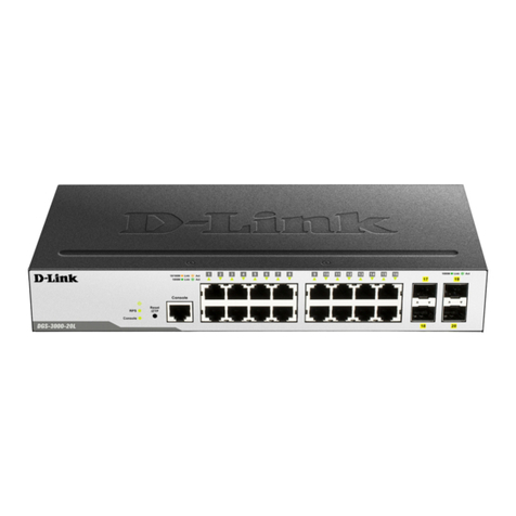
Figure 1.5 – DGS-1100-08 Front Panel
Power LED: The Power LED lights up when the Switch is connected to a power source.
Link/Act/Speed LED (Ports 1-8): 10/100/1000 Mbps ports to connect Ethernet devices to the switch.
Rear Panel
Figure 1.6 – DGS-1100-08 Rear Panel
Power: Input for a 5V/1A AC adapter.
Reset: Press the Reset button for 1 to 5 seconds to reboot the Switch. Press the Reset button for 6 to10
seconds to reset the Switch back to the default settings. The LED will light up solid amber for 2 seconds.
When pressing the Reset button for longer than 10 seconds, the device will enter loader mode and the LED
will light up solid green for 2 seconds. If the device cannot reboot, it will automatically enter loader mode.
Alternatively, you can press Reset to power up the device and enter loader mode.
Kensington Lock: This is used to attach a physical Kensington security lock.
GND: This is used to connect the Switch to ground.
DGS-1100-08P
8-Port 10/100/1000Mbps PoE Smart Managed Switch.
1 Product Introduction D-Link Smart Managed Switch User Manual
5
5
Front Panel
Figure 1.7 – DGS-1100-08P Front Panel
Power LED: The Power LED lights up when the Switch is connected to a power source.
Reset: Press the Reset button for 1 to 5 seconds to reboot the Switch. Press the Reset button for 6 to10
seconds to reset the Switch back to the default settings. The LED will light up solid amber for 2 seconds.
When pressing the Reset button for longer than 10 seconds, the device will enter loader mode and the LED
will light up solid green for 2 seconds. If the device cannot reboot, it will automatically enter loader mode.
Alternatively, you can press Reset to power up the device and enter loader mode.
Link/Act/Speed LED (Ports 1-8):
Flashing: Indicates a network link through the corresponding port.
Blinking: Indicates that the Switch is either sending or receiving data to the port.
Green: Indicates that the port is running at 1000M.
Amber: Indicates that the port is running at 10/100M.
Light off: No link.
PoE MAX. LED:
Light up: Indicates the power output to PDs is over 57W. No additional PDs can be powered for
safety consideration.
Blinking: Indicates if the user unplugged certain PDs and made the PoE power budget left over 7W,
the PoE MAX LED will blink 5 seconds.
Light off: Indicates the power budget is using less than 57W.
PoE LED (Ports 1-8):
Green: Indicates the PoE powered device (PD) is connected and the port supplies power
successfully.
Red: The PoE port has failed, possibly due to:
1. PoE total power budget shortage.
2. Over current: Exceeds the power current of powered device's classification.
3. Short circuit: Short circuit has been performed on a powered device.
Light off: Indicates no Powered Device (PD) connected.
PoE Mode LED (Port 1-8):
Solid Green: PD device insert and power feeding.
Solid Amber: PD device insert but failure occurs.
Light off: No PD device insert.
Rear Panel
Figure 1.8 – DGS-1100-08P Rear Panel
Power: Input for a 54V/1.574A AC adapter.
Kensington Lock: This is used to attach a physical Kensington security lock.
GND: This is used to connect the Switch to ground.
1Product Introduction D-Link Smart Managed Switch User Manual
6
NOTE: The power budget is 64 Watts for DGS-1100-08P.
LED Indicators
The Switches feature LED indicators for Power and Link/Act for each port. The following shows the LED
indicators for the DGS-1100-05/05PD/08/08PD switches along with an explanation of each indicator.
Figure 1.9 –LED Indicators on DGS-1100 series
Location Indicator LED Color Status Description
Per Device
Power Green
Solid Light The device is powered on.
Blinking PoE Pass Through Off (DGS-1100-
05PD only)
Light off The device is powered off.
PoE Max.
(Only DGS-1100-
08P) Red
Solid Light
When the power output to PDs is over
57W. No additional PDs can be
powered for safety consideration.
Blinking
If the user unplugged certain PDs and
made the PoE power budget left over
7W, the PoE MAX LED will blink 5
seconds.
Light off
When the power budget is using less
the 57W.
LED Per
10/100/1000
Mbps Port Link/Act/Speed Green/Amber
Solid Green
Indicates there is a 1000 Mbps
connection on this port.
Blinking
Green
Indicates data is being processed on
this port at 1000 Mbps.
Solid Amber
Indicates there is a 10/100 Mbps
connection on this port.
Blinking
Amber
Indicates data is being processed on
this port at 10/100 Mbps.
Light off
Indicates there is no active link on this
port.
LED Per PoE Port
PoE Status Green/Amber
Solid Green PD device insert and power feeding.
Solid Amber
PD device insert but failure occurs.
(PSE can’
t provide power to PD due to
PD error or power budget is not
enough.)
Light off No PD device inserts.
LED Per PD Port
(DGS-1100-05PD
only) PD Status Green/Amber Solid Green Receiving power from PSE per 802.3at
Solid Amber
Receiving power from PSE per PSE.
1 Product Introduction D-Link Smart Managed Switch User Manual
7
7
Light off No link.