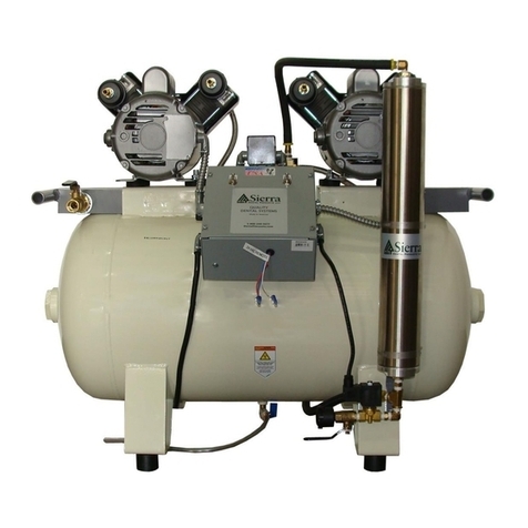
Dürr Technik HB-304M User manual

Oil-free Marathon stations with/
without membrane-drying unit
Installation and operating instructions
1036100102L02
1904V002
EN


1036100102L02 1904V002 1
6.3 Information about electrical con-
nections . . . . . . . . . . . . . . . . . . . . 18
7 Transport . . . . . . . . . . . . . . . . . . . . . . . 19
8 Installation . . . . . . . . . . . . . . . . . . . . . . 19
8.1 Remove the transport locks . . . . . 19
8.2 Establishing the compressed air
connection . . . . . . . . . . . . . . . . . . 19
8.3 Installing the unit with the mem-
brane-drying unit. . . . . . . . . . . . . . 20
8.4 Pressure reducer (optional) . . . . . . 21
8.5 Draining the condensation water . . 21
8.6 Electrical connections . . . . . . . . . . 22
9 Commissioning. . . . . . . . . . . . . . . . . . . 23
9.1 Check the motor protection
switch. . . . . . . . . . . . . . . . . . . . . . 23
9.2 Checking the switch-on/cut-off
pressure . . . . . . . . . . . . . . . . . . . . 23
9.3 Checking the safety valve . . . . . . . 24
9.4 Adjusting the rate of flow at the
pressure reducer. . . . . . . . . . . . . . 24
9.5 Adjustment options. . . . . . . . . . . . 25
10 Circuit diagrams . . . . . . . . . . . . . . . . . . 27
10.1 Unit 1036100100 . . . . . . . . . . . . . 27
10.2 Unit 1036100600 . . . . . . . . . . . . . 28
10.3 Unit 1036100620 . . . . . . . . . . . . . 29
10.4 Unit 1036100630 . . . . . . . . . . . . . 30
Usage
11 Operation . . . . . . . . . . . . . . . . . . . . . . . 31
11.1 Switching the unit on/off . . . . . . . . 31
12 Maintenance. . . . . . . . . . . . . . . . . . . . . 32
12.1 Maintenance schedule . . . . . . . . . 32
12.2 Replacing the air intake filter . . . . . 33
12.3 Replacing the filter of the mem-
brane drying unit. . . . . . . . . . . . . . 33
12.4 Taking out of use. . . . . . . . . . . . . . 34
Troubleshooting
13 Tips for operators and service techni-
cians. . . . . . . . . . . . . . . . . . . . . . . . . . . 35
14 Tips for service technicians . . . . . . . . . 36
EN
Contents
Important information
1 About this document . . . . . . . . . . . . . . . 3
1.1 Warnings and symbols . . . . . . . . . . 3
1.2 Copyright information . . . . . . . . . . . 3
2 Safety . . . . . . . . . . . . . . . . . . . . . . . . . . . 4
2.1 Intended use. . . . . . . . . . . . . . . . . . 4
2.2 Improper use . . . . . . . . . . . . . . . . . 4
2.3 General safety information. . . . . . . . 4
2.4 Specialist personnel . . . . . . . . . . . . 4
2.5 Electrical safety. . . . . . . . . . . . . . . . 4
2.6 Only use original parts. . . . . . . . . . . 4
2.7 Transportation and storage . . . . . . . 4
2.8 Disposal . . . . . . . . . . . . . . . . . . . . . 5
Product description
3 Overview. . . . . . . . . . . . . . . . . . . . . . . . . 6
3.1 Scope of delivery . . . . . . . . . . . . . . 6
3.2 Optional accessories. . . . . . . . . . . . 6
3.3 Wear parts and replacement
parts. . . . . . . . . . . . . . . . . . . . . . . . 6
4 Technical data . . . . . . . . . . . . . . . . . . . . 7
4.1 P2B-304, article 1036100100 . . . . . 7
4.2 HB-304M, article 1036100600 . . . . 8
4.3 H2A-160M, article 1036100620 . . 10
4.4 P2B-304M, article 1036100630 . . 12
4.5 Declaration of conformity for ma-
chines in accordance with the
2006/42/EC Directive . . . . . . . . . . 14
4.6 Type plate . . . . . . . . . . . . . . . . . . . 15
5 Operation . . . . . . . . . . . . . . . . . . . . . . . 16
5.1 Unit without membrane-drying
unit . . . . . . . . . . . . . . . . . . . . . . . . 16
5.2 Unit with membrane drying unit . . . 17
Assembly
6 Requirements . . . . . . . . . . . . . . . . . . . . 18
6.1 Installation/setup room . . . . . . . . . 18
6.2 Setup . . . . . . . . . . . . . . . . . . . . . . 18
2 1036100102L02 1904V002
Contents
Contact
15 Addresses . . . . . . . . . . . . . . . . . . . . . . 37
15.1 Returns / Repairs . . . . . . . . . . . . . 37
15.2 To order spare parts . . . . . . . . . . . 37
15.3 Service . . . . . . . . . . . . . . . . . . . . . 37
15.4 Addresses worldwide . . . . . . . . . . 37
EN

1036100102L02 1904V002 3
The signal word differentiates between four
levels of danger:
– DANGER
Immediate danger of severe injury or death
– WARNING
Possible danger of severe injury or death
– CAUTION
Risk of minor injuries
– NOTICE
Risk of extensive material/property damage
Other symbols
These symbols are used in the document and
on or in the unit:
Note, e.g. specific instructions regarding
efficient and cost-effective use of the unit.
Refer to Operating Instructions.
CE labelling
Date of manufacture
Order number
Serial number
Dispose of the unit properly and in ac-
cordance with applicable national, re-
gional and local laws.
Air
Switch off and de-energise the unit
(e.g.unplug from mains).
1.2 Copyright information
All names of circuits, processes, names, soft-
ware programs and units used in this document
are protected by copyright.
The reprinting of the installation and operating
instructions, even in extracts, is only permitted
with the written permission of Dürr Technik.
1 About this document
These installation and operating instructions
represent a part of the unit. They correspond to
the relevant version of the unit and the status of
technology valid at the time of its market launch.
In the event that the instructions and
notes in these installation and operating
instructions for are not observed, Dürr
Technik accepts no warranty or liability of
any kind for the safe operation and relia-
ble function of the units.
This translation was prepared to the best of our
knowledge. The original German language ver-
sion of the manual is the definitive version. Dürr
Technik is not liable for translation errors.
1.1 Warnings and symbols
Warnings
The warnings in this document are intended to
draw your attention to possible injury to persons
or damage to machinery.
The following warning symbols are used:
General warning symbol
Warning – dangerous high voltage
Warning – hot surfaces
Warning - automatic start-up of the unit
The warnings are structured as follows:
Description of the type and source of
danger
Here you will find the possible conse-
quences of ignoring the warning
iFollow these measures to avoid the
danger.
Important information
EN

4 1036100102L02 1904V002
Important information
2.4 Specialist personnel
Operation
Unit operators must ensure safe and correct
handling based on their training and knowledge.
iInstruct or have every operator instructed in
the handling of the unit.
Installation and repairs
iAlways arrange for any assembly work, read-
justments, alterations, extensions, and repairs
to be performed by Dürr Technik or by per-
sonnel authorised and trained by Dürr Tech-
nik. Qualified personnel are defined as those
trained by Dürr Technik; who are familiar with
the unit technology; and are aware of the dan-
gers presented by the unit.
2.5 Electrical safety
iObserve and comply with all the relevant elec-
trical safety regulations when working on the
unit.
iReplace any damaged cables or plugs imme-
diately.
2.6 Only use original parts
iOnly use accessories and special accessories
that are specified or approved by Dürr Tech-
nik.
iOnly use original working and spare parts.
Dürr Technik accepts no liability for dam-
age resulting from the use of non-ap-
proved accessories, special accessories
or any working parts or spare parts other
than original parts.
2.7 Transportation and storage
The original packaging provides optimum pro-
tection for the unit during transport.
Dürr Technik will not accept any respon-
sibility or liability for damage occurring
during transport due to the use of incor-
rect packaging, even where the unit is
still under guarantee.
– Only transport the unit in its original packag-
ing.
– Keep the packing materials out of the reach
of children.
2 Safety
Dürr Technik has developed and constructed
the units in such a way that danger is to a large
extent excluded if the units are used as intend-
ed. Nevertheless, residual risks can remain.
You should therefore observe the following
notes.
2.1 Intended use
The unit is intended for the compression of at-
mospheric air.
The unit has been designed for operation in dry,
ventilated rooms. The unit must not be operated
in a damp or wet environment. Its use in the vi-
cinity of gases or flammable liquids is prohibited.
Only operate the mobile units in an upright posi-
tion.
2.2 Improper use
Any other usage or usage beyond this scope is
deemed to be improper. The manufacturer ac-
cepts no liability for damage resulting from such
use. In such cases, the user/operator will bear
the sole risk.
WARNING
Serious injury and material damage
due to improper usage
iConveying explosive mixtures in any
way other than that specified is not
permitted.
2.3 General safety information
iWhen operating this unit, always observe all
directives, laws, and other rules and regula-
tions applicable at the site of operation.
iCheck the function and state of the unit prior
to each use.
iDo not convert or modify the unit.
iComply with the specifications of the Installa-
tion and Operating Instructions.
iEnsure that the unit operator has access to
the Installation and Operating Instructions at
all times.
EN

1036100102L02 1904V002 5
Important information
WARNING
Risk of explosion of the pressure
vessel and pressure hoses
iThe pressure vessel and the pressure
hoses must be vented before they are
stored or transported.
iProtect the unit from moisture during
transportation.
iAlways transport the unit in an upright
position.
iOnly transport the unit using the
transport handles provided.
iDo not transport the unit by the air in-
take filter.
The unit may be stored in its original packaging
– in warm, dry and dust-free rooms;
– protected from contaminants.
If possible, retain the packaging material.
2.8 Disposal
Unit
Dispose of the unit properly and in ac-
cordance with applicable national, re-
gional and local laws.
Packaging
Dispose of the packaging material in an
environmentally responsible manner.
– Note current disposal routes.
– Keep the packing materials out of the reach
of children.
EN

6 1036100102L02 1904V002
3 Overview
3.1 Scope of delivery
The following items are included in the scope of
delivery (possible variations due to country-spe-
cific requirements and/or import regulations):
Product name . . . . . . . . . . . . . Article number
P2B-304, 400V, with condensate
drain . . . . . . . . . . . . . . . . . . . . . . . 1036100100
HB-304M, 400V, with membrane-dry-
ing unit . . . . . . . . . . . . . . . . . . . . . 1036100600
H2A-160M, 230V, 1~, with mem-
brane-drying unit. . . . . . . . . . . . . . 1036100620
P2B-304M, 230V, 3~, with mem-
brane-drying unit. . . . . . . . . . . . . . 1036100630
– Pressure vessel
– Compressor unit
– Fabric reinforced hose
– Hose nozzle
– Installation and Operating Instructions
– Collector tray
3.2 Optional accessories
The following optional items can be used with
the device:
Pressure reducer. . . . . . . . . . . . . . 1013100027
3.3 Wear parts and replacement
parts
The following working parts need to be changed
at regular intervals (refer to the "Maintenance"
section):
Product name . . . . . . . . . . . . . Article number
Air intake filter cartridge, long . . . . 0714200050
Fine filter cartridge 0.01 µm. . 9000-416-0035ET
Fine filter cartridge 3 µm . . . . . . . . 1610-121-00
Sintered filter. . . . . . . . . . . . . . . . . 1650-101-00
Vibration damper set. . . . . . . . . . . 1035100410
Any repairs exceeding routine mainte-
nance may only be carried out by quali-
fied personnel or our service.
If the mains cable of this unit is damaged
it must only be replaced by an original
mains cable from the manufacturer.
Product description
EN

1036100102L02 1904V002 7
Product description
4 Technical data
4.1 P2B-304, article 1036100100
Electrical data 1036100100
Voltage V400 / 3~
Electrical frequency Hz 50 60
Rated power kW 4.4 6.0
Nominal current at 8 bar (0.8 MPa) A8.8 9.6
Motor protection switch, recommended
setting A4.4 5.0
Speed min-1 1440 1700
Type of protection IP X4
Mains fusing A10 **
Mains connection CEE 16 A 3L + N + PE, PVC hose connection 5 x 1.5
mm²; length: 2.5 m;
** Circuit breaker fuse characteristics B, C or D in accordance with DINEN60898
General technical data
Pressure vessel volume L 90
Delivery at 5 bar (0.5 MPa) l/min 430 480
Pressure build-up phase 0 - 7.5 bar (0 -
0.75 MPa) approx. s90 80
Duty cycle %100
Initial pressure/Cut off pressure bar (MPa) 6.5 / 8.5 (0.65 / 0.85)
Safety valve, maximum permissible oper-
ating pressure bar (MPa) 10 (1)
Pressure dew point (at 7bar/0.7MPa) °C ≤+5
Dimensions (W x H x D) cm 102 x 76 x 62
Weight kg 143
Noise level dB(A) 74 77
Ambient conditions during storage and transport
Temperature °C -10 to +55
Relative humidity %max. 95
Ambient conditions during operation
temperature °C +5 to +40
Ideal temperature °C +10 to +25
Relative humidity %Max. 95
EN

8 1036100102L02 1904V002
Product description
4.2 HB-304M, article 1036100600
Electrical data 1036100600
Nominal voltage V400 / 3~
Electrical frequency Hz 50 60
Nominal current at 8 bar (0.8 MPa) A4.4 4.8
Motor protection switch, recommended
setting A5.0 5.0
Speed min-1 1440 1700
Type of protection IP 24
Mains fusing * A10
Max. permissible mains impedance in
acc. with EN61000-3-11 ** W ≤ 0.24
* Circuit breaker fuse characteristics B, C or D in acc. with EN60898-1
** Mains impedance at 6 switching cycles per hour. If the number of switching cycles per hour is
higher, a lower mains impedance is required.
General technical data
Pressure tank volume l50
Suction power, approx. l/min 420 505
Delivery at 5 bar (0.5 MPa) l/min 215 240
Pressure build-up phase 0 - 7.5 bar (0 -
0.75 MPa) c. s105 95
Duty cycle %100
Start-up pressure bar (MPa) 6 (0.6)
Cut-off pressure bar (MPa) 7.8 (0.78)
Cut-off pressure, max. adjustable bar (MPa) 9.5 (0.95)
Safety valve, maximum permissible oper-
ating pressure bar (MPa) 10 (1)
Pressure dew point at 7bar (0.7MPa) * °C ≤+5
Dimensions (H x W x D) ** cm 76 x 74 x 52
Weight kg 82
Noise level ***
without sound insulation
with sound insulation
dB(A)
dB(A)
70
54
75
55
* Value determined at an ambient temperature of +40°C
** Values without accessories and add-on parts
*** Noise level in accordance with ENISO1680 "Airborne noise emissions"; measured in a room
with sound damping. The levels are average values with a tolerance of ± 1.5 dB(A). Higher val-
ues may be obtained in rooms with reverberating sound characteristics.
Filter mesh size
Compressor air intake filter µm 3
Fine filter cartridge 3 µm for mem-
brane-drying unit µm 3
Fine filter cartridge 0.01 µm for mem-
brane-drying unit µm 0.01
Sintered filter for membrane drying unit µm 35
EN

1036100102L02 1904V002 9
Product description
Ambient conditions during storage and transport
Temperature °C -10 to +55
Relative humidity %max. 95
Ambient conditions during operation
Temperature °C +10 to +40
Ideal temperature °C +10 to +25
Relative humidity %max. 95
EN

10 1036100102L02 1904V002
Product description
4.3 H2A-160M, article 1036100620
Electrical data 1036100620
Nominal voltage V230 / 1~
Electrical frequency Hz 50 60
Nominal current at 8 bar (0.8 MPa) A12.2 14.3
Motor protection switch, recommended
setting A6.5 7.6
Speed min-1 1410 1690
Type of protection IP 24
Mains fusing * A20
* Circuit breaker fuse characteristics B, C or D in acc. with EN60898-1
General technical data
Pressure vessel volume L 50
Suction power, approx. l/min 420 505
Delivery at 5 bar (0.5 MPa) l/min 230 260
Pressure build-up phase 0 - 7.5 bar (0 -
0.75 MPa) approx. s115 100
Duty cycle %100
Switch-on pressure bar (MPa) 6 (0.6)
Cut off pressure bar (MPa) 7.8 (0.78)
Cut off pressure, max. adjustable bar (MPa) 9.5 (0.95)
Safety valve, maximum permissible oper-
ating pressure bar (MPa) 10 (1)
Pressure dew point at 7bar (0.7MPa) * °C ≤+5
Dimensions (H x W x T) *** cm 76 x 79 x 52
Weight kg 90
Noise level ****
without sound insulation
with sound insulation
dB(A)
dB(A)
69
55
74
56
* Value determined at an ambient temperature of +40°C
** With ORANGE rinsing nozzle
*** Values without accessories and add-on parts
**** Noise level in accordance with ENISO1680 "Airborne noise emissions"; measured in a room
with sound damping. The levels are average values with a tolerance of ± 1.5 dB(A). Higher val-
ues may be obtained in rooms with reverberating sound characteristics.
Filter mesh size
Compressor air intake filter µm 3
Fine filter cartridge 3 µm for mem-
brane-drying unit µm 3
Fine filter cartridge 0.01 µm for mem-
brane-drying unit µm 0.01
Sintered filter for membrane drying unit µm 35
EN

1036100102L02 1904V002 11
Product description
Ambient conditions during storage and transport
Temperature °C -10 to +55
Relative humidity %max. 95
Ambient conditions during operation
Temperature °C +10 to +40
Ideal temperature °C +10 to +25
Relative humidity %max. 95
EN

12 1036100102L02 1904V002
Product description
4.4 P2B-304M, article 1036100630
Electrical data 1036100630
Nominal voltage V230 / 3~
Electrical frequency Hz 50 60
Nominal current at 8 bar (0.8 MPa) A15.2 16.6
Motor protection switch, recommended
setting A 9 9
Speed min-1 1440 1700
Type of protection IP 24
Mains fusing * A20
Max. permissible mains impedance in
acc. with EN61000-3-11 ** W ≤0.445
* Circuit breaker fuse characteristics B, C or D in acc. with EN60898-1
** Mains impedance at 6 switching cycles per hour. If the number of switching cycles per hour is
higher, a lower mains impedance is required.
General technical data
Pressure vessel volume L 90
Suction power, approx. l/min 845 1010
Delivery at 5 bar (0.5 MPa) l/min 430 480
Pressure build-up phase 0 - 7.5 bar (0 -
0.75 MPa) approx. s90 80
Duty cycle %100
Switch-on pressure bar (MPa) 6.5 (0.65)
Cut off pressure bar (MPa) 8.5 (0.85)
Cut off pressure, max. adjustable bar (MPa) 9.5 (0.95)
Safety valve, maximum permissible oper-
ating pressure bar (MPa) 10 (1)
Pressure dew point at 7bar (0.7MPa) * °C ≤+5
Dimensions (H x W x T) ** cm 76 x 102 x 62
Weight kg 143
Noise level *** dB(A) 69 74
* Value determined at an ambient temperature of +40°C
** Values without accessories and add-on parts
*** Noise level in accordance with ENISO1680 "Airborne noise emissions"; measured in a room
with sound damping. The levels are average values with a tolerance of ± 1.5 dB(A). Higher val-
ues may be obtained in rooms with reverberating sound characteristics.
Filter mesh size
Compressor air intake filter µm 3
Fine filter cartridge 3 µm for mem-
brane-drying unit µm 3
Fine filter cartridge 0.01 µm for mem-
brane-drying unit µm 0.01
Sintered filter for membrane drying unit µm 35
EN

1036100102L02 1904V002 13
Product description
Ambient conditions during storage and transport
Temperature °C -10 to +55
Relative humidity %max. 95
Ambient conditions during operation
Temperature °C +10 to +40
Ideal temperature °C +10 to +25
Relative humidity %max. 95
EN

14 1036100102L02 1904V002
Product description
4.5 Declaration of conformity for machines in accordance with the 2006/42/
EC Directive
We hereby declare that the unit described below conforms to all requirements of the machine direc-
tive 2006/42/EC.
The unit named below fulfills the requirements of the following directives:
– Electromagnetic Compatibility (EMC) Directive 2014/30/EU
– Simple pressure vessel directive 2014/29/EU
– The assembly contains a pressure units covered by directive 2014/68/EC in its current version.
– RoHS directive 2011/65/EU
Manufacturer's name: Dürr Technik GmbH & Co. KG
Manufacturer's address:
Pleidelsheimer Straße 30
D-74321 Bietigheim-Bissingen
Reference number: 1036
Article designation: Oil-free Marathon stations
From the serial number: L400000
We hereby declare that the unit may only be commissioned once it has been established that the ma-
chine into which this unit is to be installed complies with the provisions as set out in Machinery Direc-
tive 2006/42/EC.
Bietigheim-Bissingen, 7 January 2019
Andreas Ripsam Proof of signature in the
Executive Board of Dürr Technik Original document held by Dürr Technik
EN

1036100102L02 1904V002 15
Product description
Unit with membrane drying unit
Complete system
The type plate of the overall system is located
on the mounting plate for the compressor unit.
1
1 Type plate for the complete system
Compressor unit
The type plate of the compressor unit is located
on the crankcase below the cylinder.
1
1 Compressor unit type plate
4.6 Type plate
Unit without membrane-drying unit
Complete system
The type plate for the complete system is locat-
ed on the pressure vessel of the unit.
1
1 Type plate for the complete system
Compressor unit
The type plate of the compressor unit is located
on the crankcase below the cylinder.
1
1 Compressor unit type plate
EN

16 1036100102L02 1904V002
Product description
5 Operation
5.1 Unit without membrane-drying
unit
34
8
9
5
7
6
2
1
1 Compressor unit
2 Air intake filter
3 Pressure vessel
4 Condensate drain valve
5 Check Valve
6 Pressure switch
7 Safety Valve
8 Pressure gauge / display
9 Pressure relief valve
The compressor unit draws in atmospheric air
and compresses it without oil. The oil-free com-
pressed air is then transported directly to the
pressure tank. The oil-free and hygienic air is
made available to the consumers in the pressure
tank.
Membrane drying unit
The type plate of the membrane drying unit is
located on the side of the membrane drying
unit.
1
1 Membrane drying unit type plate
EN

1036100102L02 1904V002 17
Product description
5.2 Unit with membrane drying unit
1
2
34
7
8
9
6
10 11
12
13
14
15
16
17
18
19
5
1 Compressor unit
2 Air intake filter
3 Pressure tank
4 Condensate drain valve
5 Non-return valve
6 Pressure switch
7 Safety valve
8 Pressure gauge/display
9 Pressure relief valve
10 Cooler with ventilating fan
11 Membrane drying unit
12 Pressure limiting valve
13 Humidity display
14 Fine or sterile filter
15 Rinsing nozzle
16 Membrane fibre
17 Sinter filter
18 Water collection chamber
19 Water outlet valve
The compressor unit draws in atmospheric air
and compresses it without oil. It then transports
the oil-free compressed air to the membrane
drying unit. The cooler and the membrane dryer
extract moisture from the compressed air. The
oil-free, hygienic and dry air is stored in the
pressure tank ready for use in connected devic-
es.
EN

18 1036100102L02 1904V002
– Unit easy to access for operation and main-
tenance.
– Easy-to-access power outlet to which the unit
is connected.
– Maintain sufficient distance to the wall (at least
20cm).
– The compressed air pipe should be routed as
closely as possible to the place of installation
(note the length of the hose supplied).
6.3 Information about electrical
connections
iEnsure that the connection to the mains pow-
er supply is established in accordance with
current valid national and local regulations and
standards governing the installation of low
voltage units.
iObserve the current consumption of the unit
to be connected.
6 Requirements
6.1 Installation/setup room
The room chosen for set up must fulfil the fol-
lowing requirements:
– Closed, dry, well-ventilated room
– Should not be a room made for another pur-
pose (e.g. boiler room or wet cell)
NOTICE
Risk of overheating due to insuffi-
cient ventilation
The units generates heat. Possibility of
heat damage and/or reduced service life
of the unit.
iDo not cover the unit.
iInstall a fan for auxiliary ventilation in
rooms where ambient temperatures
exceed ≥40 °C while the unit is in op-
eration.
≥ 40 °C
6.2 Setup
The following conditions must be taken into ac-
count for installation:
The air is filtered when it is sucked in.
This does not alter the composition of
the air. For this reason it is important to
keep the sucked-in air free of harmful
substances (e.g.do not suck in exhaust
gases or contaminated exhaust air).
– Clean, level and sufficiently stable subsurface
(note the weight of the unit).
– Type plate easy to read.
Assembly
EN
This manual suits for next models
3
Table of contents
Popular Compressor manuals by other brands

Milwaukee
Milwaukee M18 FUEL 2840-20 Operator's manual

EINHELL
EINHELL RT-AC 300/50/10 operating instructions

American Eagle
American Eagle SRS-65 owner's manual

AERZEN
AERZEN VML Series Installation, assembly and operating instructions

Indel B
Indel B TB16AM Instructions for use

Prebena
Prebena PKT-fillmaster 350 Operating and maintenance instructions