LG GVH282PAB User manual

SPECIFICATION for APPROVAL
Rotary Compressor
MODEL: GVH282PAB
Doc. No. LGETH -180704-054
Rev. No. 0
Date Jul. 04. 2018
Page 1 / 24
LG Electronics
Please return one copy on your approval.
Please read this specification thoroughly before installation or operating.
Designed Approved
Sign
Date
APPROVAL
Sign
Date
EMBRITAL

LGETH -180704-054 / Rev. 0LG Electronics
No Date Article Description Writer
Revision History
Contents
1. Specification
1.1 Compressor
1.2 Motor
1.3 Wire Diagram
1.4 Electrical Component
1.5
Performance
Page 2 / 24GVH2 2PAB
1.5
Performance
1.6 Noise, Vibration
1.7 Minimum Starting Voltage
1.8 Voltage Range
1.9 Others
2. Delivered Parts List
3. Operating Limit
4. Label
5. Attachment
5.1 Compressor Drawing
5.2 Accessory Fitting
5.3 Part Drawings
5.4 OLP Characteristic Curve
5.5 Guideline for using R410A

LGETH -180704-054 / Rev. 0LG Electronics
1.Specification
1.1 Compressor
1 Model Name GVH282PAB
2 Compressor Type Hermetic Motor Compressor
3 Compression Type Rotary Type (Rolling Piston Type)
4 Application Refrigeration system (Cooling & Heating)
5 Refrigerant R410A
6 Safety Approval VDE
7 Oil / Oil Charging Amount PVE or Equivalent / 600 cc
8 Displacement 28.2 ㎤ / rev
9 Painting Black Color Paint
10
Net Weight ( Including Oil )
20.1
kg
Page 3 / 24GVH2 2PAB
1.2 Motor
10
Net Weight ( Including Oil )
20.1
kg
11 Suction Tube I.D Ø 12.8 mm
12 Discharge Tube I.D Ø 9.7 mm
Motor Type / Starting Type Single Phase Induction Motor / PSC
Pole / Rated Output 2 Pole / 1,950 Watts
Power Source 220 - 240V~ 50 Hz
Rated Revolution 2,872 rpm
Insulation Class E Class
Windings Resistance
( at 25 ℃ )
Main 1.53 ± 7% [ Ω ]
Sub 2.10 ± 7% [ Ω ]
Locked Rotor Ampere 51 A (At 240V)

LGETH -180704-054 / Rev. 0LG Electronics
1.3 Wiring diagram
1. Electrical Component
Running Capacitor 55 MFD / 400 VAC
Overload Protector INTERNAL TYPE
※Make Sure to connect right way same with the wiring diagram.
Line
Running Capacitor Compressor
C
S
R
O.L.P
Page 4 / 24GVH2 2PAB
1.5 Performance
☞Rated Conditions (ASHRAE-T Condition)
Cond. Temp. : 54.4 ℃( 130 ℉)
Evap. Temp. : 7.2 ℃( 45 ℉)
Return Gas Temp. : 35.0 ℃( 95 ℉)
Liquid Temp. : 46.1 ℃( 115 ℉)
Ambient Temp. : 35.0 ℃( 95 ℉)
Voltage 220V 240 V
Cooling Capacity (-5%↑) [ BTU/h ] 24,200 24,400
[ W ] 7,092 7,150
Power Input (+5%↓) [ Watts ] 2,315 2,335
EER (-5%↑) [ BTU/Whr ]
[ W / W ]
10.45 10.45
3.06 3.06
Running Current [ A ] 10.8 10.1

LGETH -180704-054 / Rev. 0LG Electronics
1.6 Noise, Vibration
Voltage At 240 V
Sound Level [ dB(A) ] 75 Max
Vibration [ µm ] 230 Max
Noise & Vibration Measuring Points
300mm
Page 5 / 24GVH2 2PAB
● Measuring points for specification approval
- Noise : 2 points ( X , Y )
- Vibration : 2 points ( A , B )
● Compressor vibration is measured by a vibration meter which is
contacted compressor A ~ B
● Test Condition :
- Standard Condition (Ps/Pd = 9.12 / 33.45 kg/cm²G)
Microphone
X
Y
300mm
300mm
Microphone
H/4
H/4H/4
H/4
H
B
A

LGETH -180704-054 / Rev. 0LG Electronics
1.7 Minimum Starting Voltage (V2) *note 1
1.8 Voltage Range (V2) *note 1
Cold Start
- Temp. Condition : 35℃
- Balanced pressure : Pd – Ps ≤ 0.5 ㎏f/㎠
Below 187 Volts
at Standard Condition 187 ~ 264 Volts
at Overload Condition 198 ~ 264 Volts
☞ Test Conditions
Standard
Con. Temp (℃)
Eva. Temp (℃)
Return Gas. Temp (℃)
54.4
7.2
35.0
Overload
63.8
10.4
25.0
Page 6 / 24GVH2 2PAB
Leak Tight Pressure
High Pressure Side 32 ㎏f / ㎠ G
Low Pressure Side -
Hydrostatic trength
Pressure
High Pressure Side 170 ㎏f / ㎠ G
Low Pressure Side 69 ㎏f / ㎠ G
Insulation Resistance
( with 500V D.C Mega Tester ) 50 ㏁ Min.
Withstand Voltage At 2,200 V / 1 Sec.
Leakage Current is less than 5 ㎃
Residual Moisture ( Karl Fisher Method ) 60 mg Max.
* Residual Impurities 70 mg Max
*)Each part was measured separately
1.9 Others
Return Gas. Temp (℃)
Ambient Temp (℃)
35.0
35.0
25.0
43.0

LGETH -180704-054 / Rev. 0LG Electronics
2.Delivered Parts List
Parts Name Type ( Model ) EA Parts Dwg. NO. Supply
LG
Compressor GVH282PAB 1 -YES NO
O.L.P INTERNAL TYPE - -YES NO
Cover, Terminal - 1 3550U-L005D YES NO
Gasket - 1 4986UHL004A YES NO
Nut, Common - 1 FAD30241201 YES NO
Washer, Customized - 1 FAF30240201 YES NO
Damper, Rubber - 3 MCQ61847401 YES NO
Sleeve, Damper - 3 4816U-L001G YES NO
Page 7 / 24GVH2 2PAB
※ ) Refer to Attachments ( Accessory Parts Drawings. )
Washer, Plain - - -YES NO
Nut, Hexagon - - -YES NO
Capacitor - - -YES NO
Screw, Earth M4*0.7 ,
Length : Max 6 mm. --YES NO

LGETH -180704-054 / Rev. 0LG Electronics
3. Operating Limit
3.1 Operation Range
Discharge Pressure [ ㎏f / ㎠G ] 42 Max
Suction Pressure [ ㎏f / ㎠G ] 3.0 ~ 13.0
Discharge Pipe Temp. [ ℃] 120 Max.
Motor Coil Temp. [ ℃] 135 Max.
Page / 24GVH2 2PAB
Area A : Normal Operating Zone
Area B : High Density Flow Zone
-During Starting within 3 minutes
Area C : During defrosting & re-starting
-Running time within 3 minutes

LGETH -180704-054 / Rev. 0LG Electronics
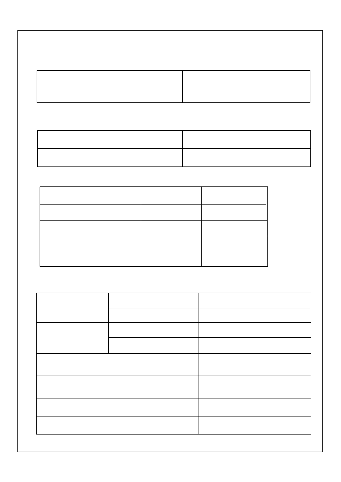
Refrigerant Charge Limit Max 2,500g
(Charge limit depends on Oil Dilution Rate**note 2 & accumulator ‘K’)
Liquid Refrigerant Back
System should be designed not to allow the liquid to go back to
compressor which cause knocking noise , current increase or
undesirable vibration and make short compressor life time.
Δ T : Temp. Difference Δ T = Case Bottom Temp.- Condensing Temp.
It must be kept Δ T ≥ 5℃
Pressure Difference
in Operating
The Pressure difference in operating shall be 5.0㎏f/㎠ or more,
but 3 minutes starting excluded.
ON/OFF Operation Each cycle should be at least 6 minutes
(ON Time : at least 3 minute , OFF Time : at least 3 minutes)
3.2 Application Limit
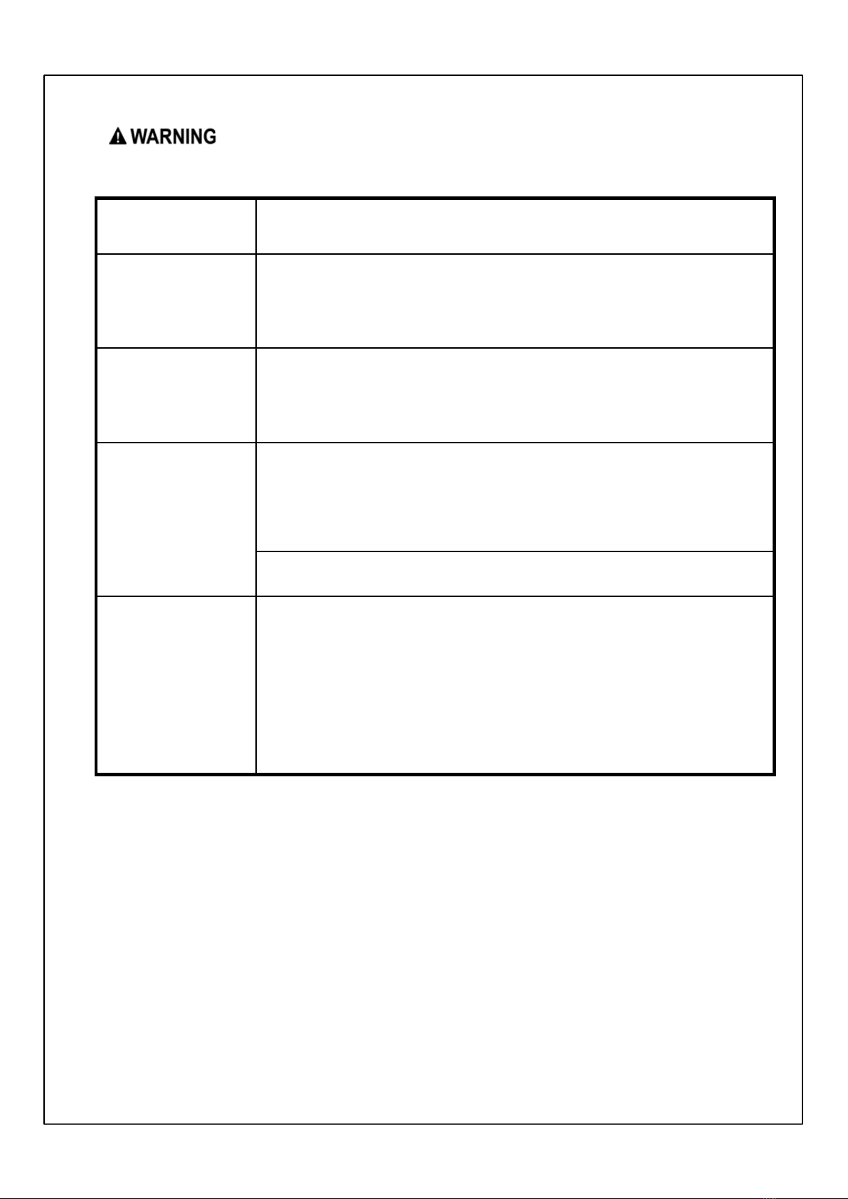
※This guide contains many important safety messages. Always read and obey all safety messages.
You can be killed or seriously injured if you don’t follow instructions.
Page 9 / 24GVH2 2PAB
(ON Time : at least 3 minute , OFF Time : at least 3 minutes)
Pressure Difference
at Starting
When starting, discharge pressure is balanced with suction pressure.
( Pd – Ps ≤ 0.5 ㎏f/㎠ )
Tilt in Operation The allowable tilt of the compressor in operation shall be 5˚ or less.
System Accumulator
The Accumulator volume should be enough to cover 50% of
maximum system refrigerant volume.
Ratio coefficient ‘K’ should be over 0.6(heating system) or 0.4(cooling
system)
Effective Volume of Accum. × Specific gravity of Refrigerant
K = --------------------------------------------------------------------------
Charged Weight of Refrigerant
※ Effective Volume of Accumulator = 580 ㎤
※ Specific Gravity of Refrigerant (R410A) = 1.085 g/㎤ ( at 20℃ )
If coefficient “K” does not meet recommendation, refrigerant system
must check liquid back phenomenon at accumulator.
Protecting Reverse
Operation
The compressor must be operated by proper voltage in accordance
with the frequency without reverse revolution condition. The reverse
revolution condition can be avoided by just keeping right order of
phase supplied power source.

LGETH -180704-054 / Rev. 0LG Electronics
Frequency Range Rated Frequency ±2%
Pipe Stress Don’t allow any force on discharge & suction pipe .
The piping stress must be less than 300㎏f/㎠at starting and stopping.
And less than 153㎏f/㎠at running.
Oil Level It must be checked oil level by the compressor with
sight glass we supply. And oil level must be kept over
guide line level **note 3. at any condition.
Protection device Refrigeration system must has the compressor protection device like
over pressure, high temperature, sensing locked pump in the controller.
When starting & running fail by abnormal overload, controller must be
able to cut off power of compressor before motor burn out.
An earth terminal should be installed to prevent electrical accidents.
3.2 Application Limit
Page 10 / 24GVH2 2PAB
Pump down
refrigerant
If pump down time is too long, compressor can be damaged due to
excessive temperature increase or poor lubrication.
Guideline of pump down process.
- Time : less than 30 seconds
- Suction Pressure : It should not run under below 1㎏f/㎠G.
And before closing a service valve, compressor running for more than 5
minutes is recommended.
※If gas charge amount of refrigerant specified is exceeded,
both parties should discuss the matter to determine compressor specification.
(accumulator volume, lubricating oil amount) and system specifications (crank case
heater, oil separator , additional accumulator, etc)
This document will be effective after LG’s receipt with your authorized signature.
When design modification is approved by the customer , the current document is
unavailable.
* Effective Period of This Document *

LGETH -180704-054 / Rev. 0LG Electronics
Use defined Refrigerant
and oil
Any process in where the HCFC’s refrigerant or the
different kind of oil against the defined. Compressor oil
are mixed should be avoided.
Avoid Damage running The running operation that inspection and the protector
inspection that affect a damage to the function and
durability of the compressor should be avoided
Running dummy indoor When the outdoor unit is operated with the indoor
dummy unit, the discharged oil should be recovered
enough
Prevent oxidation in pipe Always purge the system and the compressor with the
dry nitrogen in order to prevent oxidation of the piping
Charging Refrigerant When charging refrigerant into the cycle, make sure that
refrigerant always be filled from the higher pressure side
(condenser exit) of the cycle.
If liquid refrigerant is sucked in to the compressor liquid
compression occurs, The discharge valve is damaged,
lubrication effectiveness degenerates and reliability drops
3.3 Process Limit
Page 11 / 24GVH2 2PAB
lubrication effectiveness degenerates and reliability drops
noticeably
Avoid Vacuum running Do not operate the compressor in a vacuum state.
Furthermore do not apply high voltage to a vacuum state
compressor. There is a danger that insulation could
degenerate, causing electric shock
Avoid Air compression Do not compress the air including the case of leakage in
the refrigeration cycle. If compressors run with air mixed,
inside the compressor is heated and pressurized , which
may cause an explosion
Promptly Assemble
compressor in line
After removing rubber plugs from compressor tubes,
Promptly use the compressor. And do not leave in the
atmosphere for 10 minutes over. If Air gets into the
compressor , accelerating degeneration of the inside of
the cycle or compressor
Wiring Wires connected to the compressor, follow the
compressor specification manual and instructions
Storage temperature -10℃ ~ 65℃
Earth connection Use compressor with grounded system only.

LGETH -180704-054 / Rev. 0LG Electronics
* Note . OIL Dilution rate
[ Unit ]
☞
Oil Weight
: [ g ]
Oil Weight
---------------------------------------------- ≥ 0.22(Heating) or 0.20(Cooling)
Refrigerant Weight + Oil Weight
※ Specific Gravity of PVE or Equivalent = 0.9 (at 20℃)
V2means minimum voltage measured between pins of hermetic terminal
at the compressor starts.
* Note 1. Voltage V
V
Page 12 / 24GVH2 2PAB
** Note 3. Oil Level Guide Line
Over Level A : Steady state at any condition.
Over Level B : Minimum level of transition period within 3minutes
☞
Oil Weight
: [ g ]
☞ Refrigerant Weight : [ g ]
MAIN BEARING
CYLINDER
SUB BEARING
Level A
Level B
H/2
H/2

LGETH -180704-054 / Rev. 0LG Electronics
. LABEL
[UNIT : mm]
All safety messages will identify the hazard, tell you how to reduce the chance of injury, and tell you
what can happen if the instructions are not followed. You are strongly advised to follow these safety
instructions.
5 30
GVH282PAB
THERMALLY PROTECTED R 10A
C31EMBS
1 PH 50Hz 220 - 2 0V~ LRA 51
SERIAL NO.
66
MADE IN THAILAND
Page 13 / 24GVH2 2PAB
*2. Compressor operating range *
This document will be effective after LG’s receipt with your authorized signature.
When design modification is approved by the customer , the current document is
unavailable.
*1. Effective Period of This Document *
The Compressor can operate within the limits of the outlined area.
Outside these operating fields, the system cause early defects in the compressor.
The compressor defects caused by applications operating outside the outlined area
will not be considered under the warranty. If the appliance be operated out of the
operating range, it must be agreed with the supplier.
* Note *
instructions.
This is the Safety alert symbol. It indicates a hazardous situation which, if not avoided,
could result in death or serious injury.
This is the Electric shock hazard symbol. It indicates a hazardous situation which, if not
avoided, could result in the electric shock.
This is the Getting burnt symbol. It indicates a hazardous situation
which, if not avoided, could cause fire.
This is the Explosion or Fire symbol. . It indicates a hazardous situation
which, if not avoided, could cause explosion or fire.

LGETH -180704-054 / Rev. 0LG Electronics
5. Attachment
PAGE
: 15
: 16
: 17 ~ 22
5.1 Compressor Drawing
5.2 Accessory Fitting
5.3 Part Drawings.
Page 14 / 24GVH2 2PAB
: 23
: 24
5.4 OLP Characteristic Curve
5.5 Guideline for using R410A

LGETH -180704-054 / Rev. 0LG Electronics
GVH282PAB
UNIT mm SCALE N / S
CHF. ENGR.DES. ENGR.
Jul. 04. 2018
Samornchai T.
LG Electronics Inc.
A/C COMP. DIV.
CUSTOMER
EMBRITAL
Jul. 04. 2018
Tanarach U.
COMP. OUT LINE
NOTES
1. PAINTING : BLACK PAINT ( ELECTRO DEPOSITION)
2. OIL : PVE or Equivalent 600 cc
3. NITROGEN CHARGED AFTER DEHYDRATION
Detail of Discharge Tube Detail of Suction Tube
10
Φ12.8
+0.15
0
10
Φ9.7 ±0.15
Page 15 / 24GVH2 2PAB
Ø 138.5 Ø 75
346.8 ±3
316.7±4
272
20 2.3
Discharge Tube Suction Tube
120.1
±3
90°
Ø176 – 19.1
±5°
Label
position

LGETH -180704-054 / Rev. 0LG Electronics
(V)
R
(U)
S
C(W)
○
◐
○
◐
POWER
SUPPLY
RUNNING
CAPACITOR
HERMETIC
TERMINAL
C ( W )
( U )
S
Accessory Fitting
Page 16 / 24GVH2 2PAB
Cover Terminal
( U )
R
S
( V )
Gasket
Cover Terminal
Washer, Plain Cover Nut, Hexagon Flange
Nut assembly torque should be below 20 ㎏f㎝.
C,S,R mark embossed on cover terminal
LG Electronics Inc.

LGETH -180704-054 / Rev. 0LG Electronics
Cover, Terminal
Drawing No. 3550U-L005D
( UNIT : ㎜ )
38.6
R
(U)
V
( )
20
S
W
C( )
21.8
29.2
45°
Page 17 / 24GVH2 2PAB
33.5
COLOR
MATERIAL REMARK
MARKS(C(W),R(U),S(V))BLACK
Lupox TE-5006F
(polybutylene terephthalate)
LG Electronics Inc.
ø6

LGETH -180704-054 / Rev. 0LG Electronics
Gasket
( UNIT : ㎜ )
Drawing No. 4986UHL004A
(V)
(W)C
S
R
(U)
Φ12
21.8
Page 1 / 24GVH2 2PAB
MATERIAL REMARK
MARKS(C(W),R(U),S(V))
SILICONE
(V)
T1.0
27
30.7
57.2
LG Electronics Inc.

LGETH -180704-054 / Rev. 0LG Electronics
5.5
Φ 12
9.2
Nut, Common
Drawing No. FAD30241201
( UNIT : ㎜ )
Page 19 / 24GVH2 2PAB
5.5
8
* MATERIAL : STEEL ( ELECTRIC PLATING OF ZINC )
LG Electronics Inc.

LGETH -180704-054 / Rev. 0LG Electronics
Washer, Customized
Drawing No. FAF30240201
Φ 5.5
Φ 15
1
( UNIT : ㎜ )
Page 20 / 24GVH2 2PAB
* MATERIAL : POLYAMIDE ( NYLON )
LG Electronics Inc.
Table of contents
Popular Compressor manuals by other brands

SABROE
SABROE SAB 193 S Engineering manual

Schneider Airsystems
Schneider Airsystems CPM 280-10-20 B Translation of the original operating manual

Gardner Denver
Gardner Denver ELECTRA-SAVER EAY Operating and service manual

Hanbell
Hanbell RTM-090 manual

J.E. Adams
J.E. Adams 8670-5WB manual

OEM
OEM 25551 instructions