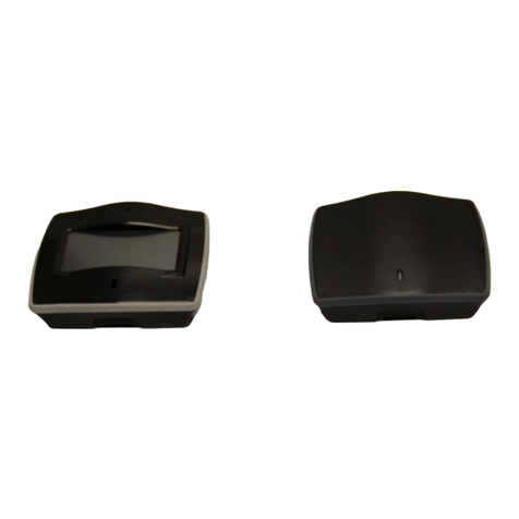
D-tect Systems MiniRad-DX User manual

INSTALLATION AND OPERATING
INSTRUCTIONS FOR THE
RADIATION DETECTION SYSTEM
D-tect Systems Group
Visionary Products Inc.
11814 South Election Road, Suite 200
Draper, UT 84020
www.dtectsystems.com

Document Number:
V024944_03_Mini_Rad-DX_Manual
Date:
1/19/2015
Page:
2 of 28
D-tect Systems
11814 South Election Rd. Suite 200, Draper, UT 84020
(801) 495-2310
FAX (801) 495-2255
Table of Contents
1Introduction .............................................................................................................................3
1.1 Key Features ...................................................................................................................3
2Getting Started Guides.............................................................................................................4
3Box Contents ...........................................................................................................................5
4Software Options.....................................................................................................................6
4.1 DX-View Software .........................................................................................................6
4.2 DX-Dashboard and DX-Dashboard Setup Tool .............................................................6
5Maximizing Battery Life.........................................................................................................6
6Recharging the MiniRad-DX...................................................................................................6
7Startup......................................................................................................................................7
8Operation.................................................................................................................................8
8.1 Communication Icons.....................................................................................................9
8.2 Graph Screen.................................................................................................................10
8.3 Main Menu Screen........................................................................................................11
8.4 Device Menu.................................................................................................................12
8.5 GPS Menu.....................................................................................................................13
8.6 Alerts Menu ..................................................................................................................14
8.6.1 Accumulative Dose ..................................................................................................15
8.6.2 Alarm Options ..........................................................................................................16
8.6.3 Setting Alarm Levels................................................................................................16
8.6.4 Optional 1 –9 Top Display ......................................................................................17
8.7 Display Menu................................................................................................................18
8.7.1 Date & Time Settings...............................................................................................18
8.7.2 Sleep Modes .............................................................................................................19
9Effective Center of Detector..................................................................................................20
10 USB Port................................................................................................................................21
11 PC Connection and Network.................................................................................................22
12 Specifications.........................................................................................................................24
13 Compliance Requirements.....................................................................................................25
14 Technical Support..................................................................................................................26
15 Warranty for D-tect System Products....................................................................................27

Document Number:
V024944_03_Mini_Rad-DX_Manual
Date:
1/19/2015
Page:
3 of 28
D-tect Systems
11814 South Election Rd. Suite 200, Draper, UT 84020
(801) 495-2310
FAX (801) 495-2255
1 Introduction
The MiniRad-DX is a handheld security and inspection device that detects emissions from
radioactive material. The MiniRad-DX system can operate as a stand-alone detector or as the
roving detection part of a larger MiniRad-DX and Rad-DX network for monitoring a building or
facility.
The MiniRad-DX is not intended to be used as a personal dosimeter.
The MiniRad-DX is not certified for explosive atmospheres.
1.1 Key Features
Device Highlights
High sensitivity detector (CsI scintillator with PMT)
Operator selectable alarm levels (password controlled)
Two bright, high-resolution display screens
Real-time dose rate graph
Units displayed in rems per hour, Sieverts per hour, or counts per second
130 hours between recharge (depending on options selected)
Integrated GPS for complete logging of dose rate, location, and time
Vibrate or audio alarm
Designed to be ANSI N42.32, N42.33 and N42.42 compliant
D-tect SensorNet (Mesh) Network
Integrated mesh radio
2.4 GHz, 15 selectable channels
Network range between devices is 1000m RF line-of-sight
Up to 50 devices per network
Easy to set-up and modify network
Interoperable with DX Link mesh relays for extended wireless range
Communication and Security
Mini USB interface
128 bit AES encryption (D-tect SensorNet)
With Network Integration
Real-time control and monitoring of an entire network via smartphone, PC, or tablet
Network can include Rad-DX area monitors and Rad-DXG portal monitors

Document Number:
V024944_03_Mini_Rad-DX_Manual
Date:
1/19/2015
Page:
4 of 28
D-tect Systems
11814 South Election Rd. Suite 200, Draper, UT 84020
(801) 495-2310
FAX (801) 495-2255
Autologging –every time a MiniRad-DX comes within range of its DX network it will
upload time, position, and alarm data –no user interaction required
2 Getting Started Guides
Additional documentation, such as Getting Started, Installation, and Quick Start Guides, is
available to help you setup your MiniRad-DX network of detectors. Software is also available
for configuration and communication including the DX-View software and the DX Cloud
Server Software (DX-Dashboard).
List of Quick Start and Installation Guides
Rad-DX Radiation Detector Quick Start Guide
DX-View Quick Start Guide
DX-Dashboard Quick Start Guide

Document Number:
V024944_03_Mini_Rad-DX_Manual
Date:
1/19/2015
Page:
5 of 28
D-tect Systems
11814 South Election Rd. Suite 200, Draper, UT 84020
(801) 495-2310
FAX (801) 495-2255
3 Box Contents
Figure 1: MiniRad-DX Handheld Radiation Detector
Other hardware components packaged with each MiniRad-DX include:
Mini USB Cable
Holster
USB Power Adapter
Table 1: Additional MiniRad-DX Hardware

Document Number:
V024944_03_Mini_Rad-DX_Manual
Date:
1/19/2015
Page:
6 of 28
D-tect Systems
11814 South Election Rd. Suite 200, Draper, UT 84020
(801) 495-2310
FAX (801) 495-2255
4 Software Options
Two different software applications are available to monitor and configure MiniRad-DX
radiation detectors.
4.1 DX-View Software
The DX-View is a PC-based software application used for configuring and monitoring your
MiniRad-DX and Rad-DX radiation detectors. The DX-View software is also used to view and
download data from one or more devices. Using this software, you can set radiation alarm
levels, view a real-time graph, download historical data and more. For more information, please
refer to the DX-View manual at http://www.dtectsystems.com/downloads.html.
4.2 DX-Dashboard and DX-Dashboard Setup Tool
The DX-Dashboard is a web server application, which can be used to monitor and control a
Rad-DX network remotely. It runs on either the D-tect Cloud Server or on the DX Network
Assistant (if installed at your facility). Using the DX-Dashboard, you can access your Rad-DX
network using any web-enabled device (smartphones, tablets, PCs). The DX-Dashboard Setup
Tool is needed to initially configure devices in the Rad-DX family to connect to
the DX Cloud Server. For more information about this software, go to
http://www.dtectsystems.com/downloads.html and download the DX-Dashboard manual.
Note: In order for MiniRad-DX devices to communicate on the DX-Dashboard software, one
Rad-DX device in the network needs to be connected to your network via Wi-Fi or Ethernet.
5 Maximizing Battery Life
The MiniRad-DX battery can last up to 130 hours with the mesh radio turned off, the GPS
capability turned off, and displays set to sleep after one minute. Turning up screen brightness,
keeping displays on longer, turning on the mesh radio and turning on GPS will require more
frequent recharging. Monitor the battery icon in the upper left corner of the front display to
determine when it is time to recharge the MiniRad-DX.
6 Recharging the MiniRad-DX
The MiniRad-DX is recharged through a USB connection. Either a USB port on a PC or a USB
wall charger can be used to recharge the MiniRad-DX.

Document Number:
V024944_03_Mini_Rad-DX_Manual
Date:
1/19/2015
Page:
7 of 28
D-tect Systems
11814 South Election Rd. Suite 200, Draper, UT 84020
(801) 495-2310
FAX (801) 495-2255
7 Startup
To power on your MiniRad-DX, press and hold the power button for about 1 second. The first
screen to appear is the Home screen. Use the buttons located below the front LCD screen to
navigate through the available menu screens.
Figure 2: Power Button

Document Number:
V024944_03_Mini_Rad-DX_Manual
Date:
1/19/2015
Page:
8 of 28
D-tect Systems
11814 South Election Rd. Suite 200, Draper, UT 84020
(801) 495-2310
FAX (801) 495-2255
8 Operation
The MiniRad-DX can operate in a stand-alone mode with information displayed directly on the
device’s front and top screens. Options for the MiniRad-DX, such as screen brightness, screen
sleep timers, and radiation units, can be set up using the following process:
1. The Home Screen will appear on the LCD screen after pressing the power button.
Figure 3: LCD Front Screen: Dose Rate and Graph
2. Pushing the upper right (power) button on the keypad again will open up the menu screen.
3. To toggle through the different screens, use the directional buttons on the keypad and the
upper left button go back to the main menu.

Document Number:
V024944_03_Mini_Rad-DX_Manual
Date:
1/19/2015
Page:
9 of 28
D-tect Systems
11814 South Election Rd. Suite 200, Draper, UT 84020
(801) 495-2310
FAX (801) 495-2255
8.1 Communication Icons
The appearance of any network connection icon indicates that the device is currently connected
and active through the referenced connection.
Battery: The battery icon is split into 5 segments. Each segment represents 20% of the total
capacity of the battery. This icon will change to a battery symbol with a lightning bolt when the
MiniRad-DX is plugged into a USB port. This indicates that the device is charging. When 20%
or less of the battery is remaining the icon will change to red indicating a low battery.
Mesh Network: The mesh network symbol indicates that the MiniRad-DX is connected to a
greater network of devices in the Rad-DX product line.
USB: The USB icon indicates that the MiniRad-DX is communicating directly with the DX-
View configuration software.
GPS: The GPS symbol indicates that your MiniRad-DX has determined its location. GPS must
be turned on to acquire a location.
Time: The current time can be displayed in the 12 hour or 24 hour format.
Battery Level
USB
Connection
Mesh Network
Connection
GPS Signal
Figure 4: Communication Icons
Time

Document Number:
V024944_03_Mini_Rad-DX_Manual
Date:
1/19/2015
Page:
10 of 28
D-tect Systems
11814 South Election Rd. Suite 200, Draper, UT 84020
(801) 495-2310
FAX (801) 495-2255
8.2 Graph Screen
The lower window on the Home screen displays the detected radiation levels in a convenient
graph timeline of 90 seconds.
The numerical dose rate and the graph window display a dose rate with a 15 second average
background filter. The background filter may be adjusted by using the DX-View software.
The graph shows a 1 second average for 30 seconds for the first 30 seconds once the device is
first powered on.
Value at Top
of Graph
Graph Window
Figure 5: Front Screen Graph

Document Number:
V024944_03_Mini_Rad-DX_Manual
Date:
1/19/2015
Page:
11 of 28
D-tect Systems
11814 South Election Rd. Suite 200, Draper, UT 84020
(801) 495-2310
FAX (801) 495-2255
8.3 Main Menu Screen
The main menu screen can be accessed by pressing the upper right navigation button on the
keypad. The available options inside the menu are Device, GPS, Alerts and Display. Use the
directional keys on the keypad to open that specific submenu. Use the upper left navigation
button to return to the main menu from the submenu screens. Press the same button to close the
main menu and return to the home screen.
Figure 6: Menu Screen

Document Number:
V024944_03_Mini_Rad-DX_Manual
Date:
1/19/2015
Page:
12 of 28
D-tect Systems
11814 South Election Rd. Suite 200, Draper, UT 84020
(801) 495-2310
FAX (801) 495-2255
8.4 Device Menu
The device menu displays device specific information including device name, firmware version,
battery state, mesh signal strength, and current mesh channel.
Settable Parameters
Parameter
Range
Default Value
Display Units
mrem/hr, CPS, µSv/hr
mrem/hr
Mesh Enable
On, Off
On
Figure 7: Device Menu

Document Number:
V024944_03_Mini_Rad-DX_Manual
Date:
1/19/2015
Page:
13 of 28
D-tect Systems
11814 South Election Rd. Suite 200, Draper, UT 84020
(801) 495-2310
FAX (801) 495-2255
8.5 GPS Menu
The GPS feature can be toggled on and off in this menu. The GPS feature is for outdoor use or
use when the device is in view of at least three satellites. The time it takes for the device to
receive latitude and longitude coordinates can vary and is dependent on your location.
Settable Parameters
Parameter
Range
Default Value
GPS Enable
On, Off
Off
Figure 8: GPS Menu

Document Number:
V024944_03_Mini_Rad-DX_Manual
Date:
1/19/2015
Page:
14 of 28
D-tect Systems
11814 South Election Rd. Suite 200, Draper, UT 84020
(801) 495-2310
FAX (801) 495-2255
8.6 Alerts Menu
When the MiniRad-DX senses gamma or x-ray radiation the front LCD screen will display the
alarm level and dose rate, the top screen will display either the dose rate or a 0-9 alarm level
depending on configuration, and the sound and vibration alarms will also activate.
The sound and vibration features can be turned on and off, and the different alarm thresholds are
also reported in this menu.
The vibration motor used in the MiniRad-DX rotates at 9500 rpm.
Settable Parameters
Parameter
Range
Default Value
Alert Vibration
On, Off
On
Alert Sound
On, Off
On
Figure 9: Alerts Menu

Document Number:
V024944_03_Mini_Rad-DX_Manual
Date:
1/19/2015
Page:
15 of 28
D-tect Systems
11814 South Election Rd. Suite 200, Draper, UT 84020
(801) 495-2310
FAX (801) 495-2255
8.6.1 Accumulative Dose
In order to view the total dose, the Mini Rad-DX device needs to be configured with the DX-View
software. See the DX-View Manual version 3 or later for more information.
The Mini Rad-DX measures accumulative dose levels for each device and displays it on the
home screen.
Figure 10: Home Screen with Accumulative Dose
In order to view the settings which have been configured with DX-View, first press the menu button and
then use the circular button to navigate to the Alerts menu. Then navigate to the “Alarm Threshold” label
and push right or left to switch between “Alarm Thresholds” and “Total Dose Levels”.
Figure 11: Total Dose Levels
Press the power button in this view to reset the dose counter.
Figure 12: Reset Dose

Document Number:
V024944_03_Mini_Rad-DX_Manual
Date:
1/19/2015
Page:
16 of 28
D-tect Systems
11814 South Election Rd. Suite 200, Draper, UT 84020
(801) 495-2310
FAX (801) 495-2255
When the accumulate dose exceeds the settings an alarm will occur causing the device to vibrate and
sound the audio alarms, if configured to do so. Also, the Total Dose Alert notice will appear on the
screen of the device. Press the top right button to acknowledge the alarm. The Mini Rad-DX will stop
alarming, but the Total Dose Caution message will continue to appear on the screen.
Resetting the Total Dose Alarm can be done by pressing the Reset Dose button on the device in the
Alerts/Alarm Thresholds menu.
8.6.2 Alarm Options
The different levels of alarm thresholds are reported in the Alerts Menu. As the radiation level
increases and the device measures above each limit, the frequency of the alarming will increase
and the alarm level will display in the upper left corner of the dose rate screen.
Figure 13: Home Screen with Alarm Triggered
8.6.3 Setting Alarm Levels
Alarm levels can be set on the MiniRad-DX using either the DX-View or DX-Dashboard
software. Both are secured by password and prevent unauthorized modification of the alarm
levels.
Alarm
Level
mrem/hr
uSv/hr
Low
0.035
0.35
Medium
0.055
0.55
High
0.1
1
Very
High
0.35
3.5
Figure 14: Default Alarm Levels

Document Number:
V024944_03_Mini_Rad-DX_Manual
Date:
1/19/2015
Page:
17 of 28
D-tect Systems
11814 South Election Rd. Suite 200, Draper, UT 84020
(801) 495-2310
FAX (801) 495-2255
8.6.4 Optional 1 –9 Top Display
The top screen can be configured to display 1 - 9 alarm levels similar to the original Mini Rad-D
radiation detector. All 9 alarm levels can be modified by the user with the DX-View software.
Alarm
Level
mrem/hr
uSv/hr
1
0.035
0.35
2
0.04
0.4
3
0.55
0.55
4
0.65
0.65
5
0.1
1
6
0.2
2
7
0.35
3.5
8
0.6
6
9
1.1
11
Figure 15: Optional 1 - 9 Alarm Level Default Settings

Document Number:
V024944_03_Mini_Rad-DX_Manual
Date:
1/19/2015
Page:
18 of 28
D-tect Systems
11814 South Election Rd. Suite 200, Draper, UT 84020
(801) 495-2310
FAX (801) 495-2255
8.7 Display Menu
This menu allows the user to customize the device’s display settings. Both screen brightness and
sleep settings will affect the time that the MiniRad-DX can operate between charges.
8.7.1 Date & Time Settings
The default time setting for the MiniRad-DX is GMT (Greenwich Mean Time). Use the DX-
View software to set the date and to set the desired time zone.
Settable Parameters
Parameter
Range
Default Value
Time Format
12hr, 24hr
12hr
Top Screen Sleep
30 sec, 1 min, 5 min, Never
1 min
Front Scr. Sleep
30 sec, 1 min, 5 min, Never
30 sec
Brightness Meter
Nine step slider
Step 6 of 9
Figure 16: Display Menu

Document Number:
V024944_03_Mini_Rad-DX_Manual
Date:
1/19/2015
Page:
19 of 28
D-tect Systems
11814 South Election Rd. Suite 200, Draper, UT 84020
(801) 495-2310
FAX (801) 495-2255
8.7.2 Sleep Modes
There are 4 options for setting sleep timers for each screen. The timers for the two screens can be
set independently of one another. The options are as follows: 30 seconds, 1 minute, 5 minutes, or
never. Enabling sleep modes allows for the device to function longer between charges.
For example, say that a security guard is carrying a MiniRad-DX with them on their rounds
through the building. Typical use would have them wearing the device on their belt. To preserve
battery life, the front screen could be set to 1 minute of inactivity before shutting off and the top
screen could be set to never sleep. This allows for continuous status monitoring through the top
screen and turning on the front screen only whn further information is needed.
Regardless of the sleep settings, the MiniRad-DX will alarm and the displays will wake if
radiation above the set threshold is encountered.

Document Number:
V024944_03_Mini_Rad-DX_Manual
Date:
1/19/2015
Page:
20 of 28
D-tect Systems
11814 South Election Rd. Suite 200, Draper, UT 84020
(801) 495-2310
FAX (801) 495-2255
9 Effective Center of Detector
The target symbol on the back label of the MiniRad-DX represents the most sensitive portion of
the detector, which is also referred to as the effective center of detection. Always point the back
of the detector toward the material or item you are measuring or scanning.
Figure 17: Effective Center of Detector
Symbol
indicating the
Effective
Center of the
Detector
This manual suits for next models
1
Table of contents
Other D-tect Systems Measuring Instrument manuals
Popular Measuring Instrument manuals by other brands

Sibata
Sibata 080150-066 Operation manual

GE
GE Hydran 201i instruction manual

Sensia
Sensia NuFlo Scanner 2000 Hardware user manual

Luceo Technologies
Luceo Technologies PARALLEX SYSTEM X-BERT Series user manual

greenTEG
greenTEG GO MEASUREMENT SYSTEM II user manual

Bosch
Bosch DLR165 Operating/safety instructions