D-tect Systems Mini Rad-V User manual

Document Number:
V013421_05_MiniRad-V_Manual_Installation_Instructions
Date:
8/28/2019
Page:
1 of 13
D-tect Systems
•
11814 South Election Rd. Suite 200, Draper, UT 84020
•
(801) 260-4000
INSTALLATION AND OPERATING
INSTRUCTIONS FOR THE
VEHICLE-MOUNTED RADIATION DETECTION SYSTEM
Generation 2
Version 5
August 2019
D-tect Systems
11814 South Election Road, Suite 200
Draper, UT 84020
www.dtectsystems.com

Document Number:
V013421_05_MiniRad-V_Manual_Installation_Instructions
Date:
8/28/2019
Page:
2 of 13
D-tect Systems
•
11814 South Election Rd. Suite 200, Draper, UT 84020
•
(801) 260-4000
1 Welcome
Congratulations on your recent purchase of the Mini Rad-V G2 Vehicle-Mounted Radiation Detector. The
Mini Rad-V quietly scans the environment around the vehicle to find any sources of gamma radiation. If
gamma radiation is detected, the Mini Rad-V gives clear audio and visual alarms proportional to the
presence of radiological materials nearby. The Mini Rad-V features a simple layout and automatically
calibrates itself to natural background radiation.
2 G2 Updates
The G2 model includes improved ruggedization enhancements to the internal electronics and the exterior
housing. Upgrades to the surface mounting and component potting on the inside of the case and a more
robust FET to contribute to a significantly improved durability and anti-shock capabilities. An anodized
aluminum shield protects the detection unit at the cable penetration. A self-diagnostic feature based on
various light sequences displayed on the display/alarm notify the user of specifi , and the installation process
was re-evaluated and is now simpler and more straightforward.
A new shield has been included to mitigate the collection of snow, ice and moisture on the Exterior Detector
housing.
The entire installation process was re-evaluated as well and is now simpler and more straightforward. That
required a new more robust FET and subsequently more revamping of the board.
3 Installation Warning
Warning: Do NOT apply power to the In-Cab Display module before connecting it to the External
Detector module.
Please read all installation instructions in section 5 before installing the Mini Rad-V system.
Applying power to the In-cab Display module before connecting the other communication cable can
provide an electrical shock and cause an electrical failure to the In-cab Display module and void the
warranty. The In-Cab Display module should always be connected to the External Detector module
BEFORE power is applied. Failure to follow the instructions in this manual may damage the unit.
4 System Overview
4.1 Modules
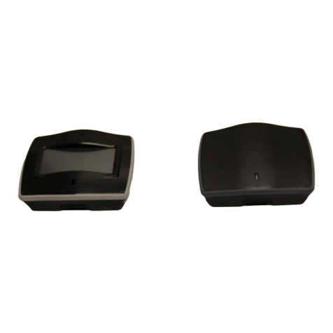
The Mini Rad-V consists of two modules: The In-Cab Display module (Figure 1: In-Cab Display Module)
and the External Detector module (Figure 2: External Detector Module). The In-Cab Display module
receives power via a cable connected to the back of the unit. The unit is powered by two lead lines attached
to the fuse box. The In-Cab Display module is connected to the External Detector module via a
communications cable.
Dimensions
•In-Cab Display Module −2.8” × 1.82” × 1” Weight: 0.4 lbs.
•External Detector Module −4.7” × 3.14” × 1.7” Weight: 1.2 lbs.

Document Number:
V013421_05_MiniRad-V_Manual_Installation_Instructions
Date:
8/28/2019
Page:
3 of 13
D-tect Systems
•
11814 South Election Rd. Suite 200, Draper, UT 84020
•
(801) 260-4000
Figure 1: In-Cab Display Module
Figure 2: External Detector Module
Figure 4: External Detector with Protective
Shield
Figure 3: Protective Shield

Document Number:
V013421_05_MiniRad-V_Manual_Installation_Instructions
Date:
8/28/2019
Page:
4 of 13
D-tect Systems
•
11814 South Election Rd. Suite 200, Draper, UT 84020
•
(801) 260-4000
4.2 External Detector Module
The External Detector module houses a 0.5” diameter x 1.5” Cesium Iodide Scintillation crystal with a
high-sensitivity photo-multiplier tube. It detects gamma radiation within the energy range of 30 keV to 3
MeV. It takes readings in less than one second.
4.3 Protective Shield
Included with the G2 model, the protective shield adds an increased level of environmental protection by
prohibiting the buildup of snow and ice on the cable and connector on the External Detector module. The
protective shield comes attached to the External Detector module.
4.4 Cables
There are 2 cables included with the Mini Rad-V –the Power cable and the Communication cable. The
Power cable connect the In-cab Display module to the vehicle power. The Communication cable connects
the In-Cab Display module to the External Detector module.
The standard cable lengths for both cables are 20 feet long. Longer cables lengths of 35’ and 50’ are offered
as options.
4.5 Maintenance
The External Detector module is designed to MIL-STD-810 environmental standards for rain, shock, and
vibration. The unit is sealed to reduce intrusion from dust, humidity, and salt fog. It may be cleaned safely
with mild soap and water using a warm, wet cloth.
5 Installation Instructions
Please refer to your vehicle manufacturer’s manual for specific installation guidance for your vehicle,
particularly for mechanical mounting of the Mini Rad-V modules, routing of the power and communication
cables, and connecting the Mini Rad-V to vehicle power. D-tect Systems assumes no responsibility for
damages to any vehicle, other electronic devices, or this product incurred during installation.
5.1 Installation Steps
Warning: Do not apply power to the In-Cab Display module until the External Detector module is
connected to the In-Cab Display module with communication cable.
The In-Cab Display module must be connected to the External Detector module BEFORE power is applied,
and the In-Cab Display module should NEVER be connected to power without the External Detector
module attached.
Please follow these instructions exactly. Failure to do so may damage the unit.
1. Mount the External Detector module to the bumper or other location as appropriate. Do NOT
connect the communication cable to the External Detector module at this time.
2. Mount the In-Cab Display module onto the dashboard of the vehicle. Do NOT connect the detector
cable to the External Detector module at this time.
3. Run the communication cable from the In-Cab Display module to the to the External Detector
module. Do not connect the cable to the External Detector module. Secure the cable to the bumper
with a zip tie. While running the cables through the vehicle, make sure to not twist the connector

Document Number:
V013421_05_MiniRad-V_Manual_Installation_Instructions
Date:
8/28/2019
Page:
5 of 13
D-tect Systems
•
11814 South Election Rd. Suite 200, Draper, UT 84020
•
(801) 260-4000
ends. Do not pull hard on or stretch the cables. Do not connect the cables to the External Detector
module or the In-Cab Display module and then allow them the hang or dangle. This can cause the
system to malfunction and fail.
4. Run the power cable from the power source to the In-Cab Display module. Do NOT connect the
cable to the power source at this time.
5. Connect the communication cable to the External Detector module.
6. Connect the communication cable to the In-Cab Display module.
7. Connect the power cable to the In-Cab Display module.
8. Connect the power cable to the power source.
9. Test to make sure the Mini Rad-V powers up and responds to a radiation source.
5.2 External Detector Module Installation
The External Detector module houses the radiation detection components and is designed to be placed on
the exterior of the vehicle. It is attached to the vehicle with four ⅛” screws (spaced 2” apart on both ends
of the module). The sensitivity of the device decreases with the amount of material between the detector
and any potential radiation sources, so it is best to mount the device in a secure location with good exposure,
such as behind the front grill or on the front bumper.
Make sure that neither the mounting equipment nor the position of the module affects the operation of the
vehicle in any way. Take special care if mounting the External Detector module under the hood to avoid
placement near the engine block, exhaust lines, compressor, or other hot/cold areas, as exposure to extreme
temperatures may damage the device. Also, make sure to avoid engine belts and electrical wires, and
confirm that the power and/or communications cables of the modules are secured and isolated from moving
parts and hot surfaces.
Figure 5: External Detector Module
•Place on the exterior of the vehicle in a
location with good exposure (i.e.
BEHIND the front grill or on the front
bumper).
•Avoid hot or cold areas of the vehicle,
such as locations near exhaust lines,
the engine block, or the radiator.
•Make sure the cable reaches from one
unit to the other before firmly securing
either unit.

Document Number:
V013421_05_MiniRad-V_Manual_Installation_Instructions
Date:
8/28/2019
Page:
6 of 13
D-tect Systems
•
11814 South Election Rd. Suite 200, Draper, UT 84020
•
(801) 260-4000
5.3 In-Cab Display Module Installation
The In-Cab Display module should be placed within easy reach of the operator and should be attached
securely to a solid surface. The module is attached to a support that is secured by three ¼” screws spaced 1
¼” apart. Make sure that the In-Cab Display module does not block the view of the driver or interfere with
vehicle controls and/or other equipment.
Contact your local Department of Transportation for information regarding regulations for dashboard-
mounted displays, as these may vary from state to state. The In-Cab Display module must be connected to
the External Detector module via the communication cable. Depending on the vehicle model and
configuration, this cable can usually be run under the dashboard and through the engine compartment.
Figure 6: In-Cab Display Module
•Place inside the cab where it is visible
from inside the vehicle but does not
obscure the driver’s view.
•Make sure the cable reaches from one
unit to the other before firmly securing
either unit.

Document Number:
V013421_05_MiniRad-V_Manual_Installation_Instructions
Date:
8/28/2019
Page:
7 of 13
D-tect Systems
•
11814 South Election Rd. Suite 200, Draper, UT 84020
•
(801) 260-4000
5.4 Installing the Mini Rad-V Cables
Figure 7: Installing Cables
•The modules are connected by the
communication cable (included).
•To connect the cable, adjust it until it fits
onto the post, then turn the cable
connector until it locks firmly into the
post.
•Make sure that the cables do not
interfere with the vehicle’s other
operating systems.
•Do not place excessive force on the
cables or the connectors.
•Do not route cables where they may be
pinched, worn excessively, or melted.

Document Number:
V013421_05_MiniRad-V_Manual_Installation_Instructions
Date:
8/28/2019
Page:
8 of 13
D-tect Systems
•
11814 South Election Rd. Suite 200, Draper, UT 84020
•
(801) 260-4000
6 System Operation
6.1 Start up
To operate the Mini Rad-V, you first need to connect the cables. Both the communication and power cables
connect to the back of the In-Cab Display module. To connect the cables, adjust the cable until it fits onto
the post, then turn the cable connector to the right until it locks firmly onto the post. To release the cable,
turn the connector in to the left until it stops. From there, the cable should pull away from the post.
When power is applied to the In-Cab Display module, the blue LED labeled ‘Power’ will light up and the
unit will begin a power-up and calibration sequence, indicated by a beep and a flashing blue LED. During
the 30 second calibration interval, the unit will measure naturally occurring background radiation and
calculate a threshold. (This threshold will be the baseline from which a radiological alert will be indicated
to the operator.) The blue LEDwill blink once more to indicate that the backgroundcalibration has finished.
If the Mini Rad-V stops detecting normal background radiation levels for a period of time (such as if it is
taken into a parking garage), the Mini Rad-V will recalibrate itself. The device will beep and the blue LED
will flash to indicate the 30 second calibration phase. When calibration is complete, the Mini Rad-V will
beep once more and go into detection mode. This keeps the Mini Rad-V at maximum sensitivity levels in
all environments.
6.2 Power
The unit can be powered by any of the following sources: a car adapter plugged into a cigarette lighter or
auxiliary power source, two lead lines attached to the fuse box, or an AC power converter for standard
outlets. After plugging in the unit, check to make sure that the blue LED on the front face of the In-Cab
Display module is on.
6.3 Alarm
The In-Cab Display module will alarm (audibly and with a blinking red LED on the front face of the In-
Cab Display module) when the presence of gamma radiation exceeds threshold background levels. The
frequency of the audio and visual alarms will increase proportionately to increasing levels of gamma
radiation. The audio alarm can be silenced by pressing the ‘mute’ button on the front face of the In-Cab
Display module. To reactivate the audio alarm, press the mute button again. The red LED will continue to
flash until the External Detector module no longer detects radiation above background levels.
6.4 Periodic Testing
A periodic test is recommended to ensure the Mini Rad-V is working properly. This test can be performed
with the use of a small radiation source such as a 1.0 µCi Cs-137 check source. Hold the small radiation
check source near the External Detector module. The In-Cab Display module will emit an audible alarm
and the small red LED light will flash.

Document Number:
V013421_05_MiniRad-V_Manual_Installation_Instructions
Date:
8/28/2019
Page:
9 of 13
D-tect Systems
•
11814 South Election Rd. Suite 200, Draper, UT 84020
•
(801) 260-4000
7 Specifications
Mission
Vehicle mounted radiation detection system
Detector
1.3 cm diam x 3.8 cm Cesium Iodide detector with a high-sensitivity photo-
multiplier tube (PMT)
Calibration
Automatic
Sensitivity
Alarms at about 55 µRem/hr
Response Time
Less than 1 second
Display
Large LED indicator for in-cab viewing
Alarm
Loud audible alarm (with acknowledge button)
Alarm Volume
> 90 dB at 10 cm
Power
12V DC
Energy Range
30 keV –3 MeV
Environment
In-Cab Display: Controlled environment, operates in high RF environments
External Detector: IP 66 Compliant, -10º F to 122º F (-23º C to 50º C)
Dimensions
In-Cab Display: 2.8” x 1.8“ x 1” (7.1 cm x 4.6 cm x 2.5 cm)
Exterior Detector: 4.7” x 3.1“ x 1.7” (11.9 cm x 7.9 cm x 4.3 cm)
Protective Shield
21-gauge anodized aluminum
Weight
In-Cab Display: 0.4 lbs. (6.4 oz)
Exterior Detector: 1.2 lbs. (19.2 oz)
Exterior Shield: 0.125 lbs. (2.0 oz)
Cables
Power Cable length: 20’
Communication Cable Length: 20’, Optional 35’ and 50’
Warranty
2-Year parts and labor. See warranty for details

Document Number:
V013421_05_MiniRad-V_Manual_Installation_Instructions
Date:
8/28/2019
Page:
10 of 13
D-tect Systems
•
11814 South Election Rd. Suite 200, Draper, UT 84020
•
(801) 260-4000
8 Trouble Shooting Guide
The Mini Rad-V In-Cab Display module emits various signals under certain conditions during bootup and
calibration, during radiation alarms, and when the system is experiencing a type of failure. The trouble
shooting table below describes various sequence, conditions and suggestions for each situation.
Table 1: Trouble Shooting Table
Sequence
Condition
Suggestion
At power on, the blue light
flashes for 30 seconds,
followed by an audible beep
and simultaneous flash of the
red light.
This is the expected sequence
at initial boot up and
calibration.
N/A
While on, the blue light starts
flashing for 30 seconds,
followed by an audible peep
and simultaneous flash of the
red light.
This is a normal sequence.
When the device senses lower
background radiation levels, it
will recalibrate.
N/A
While the blue light is on, the
red light begins to flash, and
the audio begins to beep.
This is the expected behavior
when detecting the presence
of gamma and x-ray radiation.
Radiation is detected. Use a Mini
Rad-D to localize the source, then
use a Rad-ID to identify the type of
radiation present.
If it is confirmed a radiation source
is not near, and the device continues
to alarm, then contact customer
service.
Constantly repeating flashing
blue light and audible beep
every 30 seconds.
Device is stuck in boot up
mode.
Power cycle (turn off/on) to see if
device self-corrects. If it does not
power up properly, contact customer
service.
Solid blue light and flashing
red light and audible beep
every 5 seconds.
Detector failure or electrical
failure.
Contact customer service.
Slowly flashing blue light and
quick, double beep every 5 to
6 seconds.
Detector failure or electrical
failure.
Contact customer service.
No blue light and no red light.
Constant audio beep.
Detector failure or electrical
failure.
Contact customer service.
No lights turn on when power
is on.
Electrical failure.
Contact customer service.

Document Number:
V013421_05_MiniRad-V_Manual_Installation_Instructions
Date:
8/28/2019
Page:
11 of 13
D-tect Systems
•
11814 South Election Rd. Suite 200, Draper, UT 84020
•
(801) 260-4000
9 Customer Service
The D-tect Systems team strives to provide the most reliable and technologically advanced radiation
detection and identification products available at affordable prices. All D-tect Systems products are
designed, engineered, and manufactured in the USA. In an effort to ensure that the user receives the
utmost in value and productivity in the use of D-tect Systems products, we have established a
knowledgeable, trained distributor network with a specific background in these types of products. Please
contact your distributor if you require additional information about our products, or if you require
immediate warranty assistance (please reference model, serial number, and date of purchase). We also
provide direct technical support resources at www.dtectsystems.com, techsupport@dtectsystems.com,
and 801-260-4000.
10 Limited Warranty for D-tect Systems Products
1. What this Warranty Covers and for How Long
D-tect Systems (“D-tect Systems”) warrants this device (the "Product") against defects in materials and
workmanship under normal use for a period of two years from the date of purchase. This warranty extends
to the first end-user purchaser only and is not transferable. This warranty does not extend to other ancillary
and/or consumable products including but not limited to batteries, calibration sources, straps, and shipping
cases. D-tect Systems, at its option, will at no charge either repair, replace or refund the purchase price of
any Products that do not conform with this warranty. Repair may include the replacement of parts with
functionally equivalent reconditioned or new parts. Replacement may include providing a functionally
equivalent Certified Reconditioned/Pre-owned or a new Product. Products that have been repaired or
replaced are warranted for the balance of the original warranty period or for 90 days from the date that the
repaired or replaced Product is received by you, whichever is longer. All Products for which replacements
have been provided will become D-tect Systems property.
2. Other Warranty Conditions
This warranty is D-tect Systems’ complete warranty for the Product. D-tect Systems assumes no obligation
or liability for changes to this warranty unless made in writing and signed by an officer of D-tect Systems.
If D-tect Systems agrees to perform services requested and approved by the customer that are not included
in either the Limited or Extended Warranty, these services will be billed to the customer at D-tect Systems’
standard prices and terms.
D-tect Systems does not warrant any installation, maintenance, or service that it did not perform. SERVICE
WORK PERFORMED BY SERVICE CENTERS NOT AUTHORIZED BY D-TECT SYSTEMS TO
PERFORM SUCH WORK WILL VOID THIS WARRANTY.
3. What This Warranty Does Not Cover
a. Defects or damage resulting from: collision of the Product with hard surfaces, contact with water,
rain or extreme humidity, contact with sand, dirt or the like, contact with extreme heat or cold,
spills of food or liquid, improper testing, operation, maintenance, installation, adjustment; or any
alteration or modification of any kind.
b. Normal “wear and tear” of the Product such as scratches, scuffs, and marks on the LCD, case and
other external features.

Document Number:
V013421_05_MiniRad-V_Manual_Installation_Instructions
Date:
8/28/2019
Page:
12 of 13
D-tect Systems
•
11814 South Election Rd. Suite 200, Draper, UT 84020
•
(801) 260-4000
c. Cracked or broken displays, buttons, or damage to other externally exposed parts caused by
abnormal use and/or abuse of the Product.
d. Products disassembled or repaired in such a manner as to adversely affect performance or prevent
adequate inspection and testing to verify any warranty claim.
e. Products on which serial numbers or date tags have been removed, altered or obliterated.
4. How to Get Warranty Service
To get warranty service, please contact your distributor or D-tect Systems at www.dtectsystems.com.
You will receive directions on how to mail the Product to D-tect Systems. All Products shipped to D-tect
Systems must be shipped with freight and insurance prepaid. Along with the Product you must include a
receipt, bill of sale, or some other comparable proof of purchase, a written description of the problem and,
most importantly, your address and telephone number. If additional information is needed, please contact
D-tect Systems at the web address indicated above.
5. General Provisions
THIS IS THE COMPLETE WARRANTY FOR THIS PRODUCT BY D-TECT SYSTEMS AND SETS
FORTH YOUR EXCLUSIVE REMEDIES. THIS WARRANTY IS GIVEN IN LIEU OF ALL OTHER
EXPRESS WARRANTIES. IMPLIED WARRANTIES, INCLUDING WITHOUT LIMITATION THE
IMPLIED WARRANTIES OF MERCHANTABILITY AND FITNESS FOR A PARTICULAR
PURPOSE, ARE GIVEN ONLY IF SPECIFICALLY REQUIRED BY APPLICABLE LAW.
OTHERWISE, THEY ARE SPECIFICALLY EXCLUDED. IN NO EVENT SHALL D-TECT SYSTEMS
BE LIABLE FOR DAMAGES IN EXCESS OF THE PURCHASE PRICE OF THE PRODUCT OR FOR
ANY INDIRECT, INCIDENTAL, SPECIAL OR CONSEQUENTIAL DAMAGES ARISING OUT OF
THE USE OR INABILITY TO USE THE PRODUCT, TO THE FULL EXTENT THESE DAMAGES
MAY BE DISCLAIMED BY LAW.
6. Patent and Software Provisions
D-tect Systems will defend at its own expense, any suit brought against you to the extent that it is based on
a claim that the Products infringe a United States patent. D-tect Systems will pay those costs and damages
finally awarded against you in any such suit which is attributable to any such claim. The defense and
payments by D-tect Systems are conditioned on the following: (a) that you will notify D-tect Systems
promptly in writing any notice of the claim; and (b) that D-tect Systems will have sole control of the defense
of the suit and all negotiations for its settlement or compromise; and (c) should the Products become, or in
D-tect System’s opinion be likely to become, the subject of a claim of infringement of a United States
patent, that you will permit D-tect Systems, at its option and expense, either: to procure for you the right to
continue using the Products or parts; to replace or modify them so that they become non-infringing; or to
grant you a credit for such Products or parts as depreciated and accept their return. The depreciation will
be an equal amount per year over the lifetime of the Products, accessories, battery or parts as established
by D-tect Systems.
D-tect Systems will have no liability to you with respect to any claim of patent infringement which is based
upon the combination of the Products or parts furnished under this limited warranty with software,
apparatus or devices not furnished by D-tect Systems. D-tect Systems will have no liability for the use of
ancillary or peripheral equipment or software not furnished by D-tect Systems which is attached to or used

Document Number:
V013421_05_MiniRad-V_Manual_Installation_Instructions
Date:
8/28/2019
Page:
13 of 13
D-tect Systems
•
11814 South Election Rd. Suite 200, Draper, UT 84020
•
(801) 260-4000
in connection with the Products. The foregoing states the entire liability of D-tect Systems with respect to
infringement of patents by the Products, accessories, batteries or any parts of them.
Laws in the United States and other countries preserve for D-tect Systems certain exclusive rights for
copyrighted D-tect Systems software such as the exclusive rights to reproduce in copies and distribute
copies of the D-tect Systems software. D-tect Systems software may be copied into, used in and
redistributed with only the Products associated with such D-tect Systems software. No other use, including
without limitation disassembly, of such D-tect Systems software or exercise of exclusive rights in such D-
tect Systems software is permitted.
Table of contents
Other D-tect Systems Measuring Instrument manuals