manuals.online logo
Brands
  1. Home
  2. •
  3. Brands
  4. •
  5. D-tect Systems
  6. •
  7. Security Sensor
  8. •
  9. D-tect Systems rad-D User manual

D-tect Systems rad-D User manual

Users Manual
LAURUS Systems, Inc. - Ph: 410-465-5558 - Fax: 410-465-5257 - www.LaurusSystems.com
Introduction
The rad-D is a security and inspection system that detects emissions from radioactive material. The rad-D
can inspect large numbers of packages, vehicles, or personnel and can be used to guard doorways and
driveways, to scan conveyor belts of luggage or packages, or to provide radiation detection on existing X-
ray scanning machines.
The rad-D can operate completely stand-alone, providing the user with information via the rad-D Alarm
Display Panel, or it can be integrated into a computer network, allowing for real-time display and
monitoring of multiple rad-D systems, as well as integration with security command and control systems.
System Components
A rad-D system consists of one to four detectors (Figure 1), an Alarm Display Panel (Figure 2) and
optional PRM Mounting Bracket (Figure 3). There are two types of detectors, a gamma detector and a
neutron detector. The gamma detector detects gamma radiation and high-energy X-rays emitted from
radioactive materials. Gamma detectors come in two varieties, a narrow-field of view detector and an
omni-directional detector. The neutron detector detects neutrons emitted from a small number of very
important radioactive materials. Any combination of one to four gamma and/or neutron detectors can be
installed and monitored by a single Alarm Display Panel.
Figure 1. Each rad-D detector is
17.5” in length and 5” in diameter.
Figure 2. The Alarm Display Panel
displays from up to 4 different detectors
Figure 3. Rad-D with PRM
Mounting Bracket System
System Installation
General Installation:
Physically mount the detectors in accordance with the guidelines discussed below for each type of
detector. A detector can be up to 50 feet away from the Alarm Display Panel. Connect the cable from
each detector into any one of four detector ports on the Alarm Display Panel. The rad-D will automatically
know which type of detector has been connected to the Alarm Display Panel. Connect the power cable to
the Alarm Display Panel. When all cables are connected, plug the power cable into a wall plug.
When power is applied, the rad-D begins a 90 second warm-up sequence. During this time the rad-D is
performing self-tests and calibrating to the natural radiation background environment. At the end of this
phase, the Alarm Display Panel will begin showing radiation counts from the gamma and/or neutron
detectors.
60 Hz and 50 Hz power
The rad-D can operate on both 60 Hz/110 VAC (United States) and 50 Hz/208 VAC power. The rad-D
comes with a plug configured for U.S. power sockets. To use in a 50 Hz environment, attach a wall plug
converter to convert the rad-D U.S. wall plug to the local country plug standard. The rad-D will
automatically adjust to the power supplied.
Alarm Display Panel:
Locate the Alarm Display Panel near the operator or where it can be read easily, unless your rad-D is
going to be read remotely via PC. The Alarm Display Panel must be within reach of a power plug and
within 50 feet of all detectors.
If the rad-D is integrated as part of a computer network via its wireless Bluetooth interface, the receiving
computer must be within 100 meters or less (depending on intervening walls) of the Alarm Display Panel.
If the rad-D is integrated as part of a computer network via its Serial Port interface, the receiving computer
must be connected using a single serial cable. The PC network displays rad-D information using the
provided rad-D software. The data format and structure of the interface is also available on request,
allowing the user to use create their own monitoring software.
Detector Installation Guidelines:
All detectors are mounted using two ½” screws separated by 4”. The detectors can be mounted in any
orientation. Each detector has unique placement requirements for maximum efficiency.
•Gamma Detector, Omni-directional: Place this detector as close to the traffic area as possible to
maximize its sensitivity. It can be oriented in any direction. This detector weighs approximately 8
pounds.
•Gamma Detector, Narrow Field-of-View: Aim the front of the detector at the target inspection area.
The front is the end opposite the cable interface. The front is very thin aluminum, so care must be
used to prevent dents or puncturing (neither, however, will degrade the operation of the unit. It just
won’t look as nice). The field-of-view is +/- 45º from the front. Ensure that the unit is as close as
possible to the inspection area while still getting good coverage of the field-of-view. This detector
weighs 30 lbs. Please take care when handling and mounting it to avoid injury to yourself or others.
Always use safe lifting practices when moving heavy objects.
•Neutron Detector: To maximize neutron detection, place the detector as close as possible to the
traffic area. It can be oriented in any direction. This detector weighs approximately 8 pounds.
PRM Mounting Bracket
•Detector, Following the detector
mounting guidelines, mount the
detector using the two ½” screws
with the front end of the detector
(opposite of the end with the
controller cable) being closest to
the Pan Control Adjustment Knob
(Figure 4)
•Base, The base of the PRM comes
with heavy duty earth magnet
assemblies that will hold the PRM
to a steel surface in any orientation
and with any of the rad-D configurations.
The base can also be mounted directly
to any surface by whatever means is
necessary to ensure the bracket is
securely in place and will hold the
appropriate rad-D model.
•Mounting Arm, The “L” shaped riser can be attached to the solid swing arm facing any direction. The
adjustment knob is compatible with all four sides of the solid swing arm and is used to tighten the
riser to the swing arm. It is also used to adjust the height of the rad-D from the base. The height
range is from 14” (356 mm) to 19” (483 mm).
Mounting on X-ray machines:
Typical rad-D installation on X-ray machines consist of a single narrow field-of-view gamma detector and
one-or-more neutron detectors. Because the X-ray machine can generate scatter that can be detected by
the gamma detector, to avoid false alarms please do not aim the front of the detector into the X-ray
machine.
Either aim the gamma detector at the conveyor belt coming into the X-ray machine, or leaving the X-ray
machine. Depending on the relative radiation noise from the X-ray machine (older machines tend to be
noisier), the rad-D may have to be tuned with the X-ray machine in a one-time operation to eliminate false
alarms. Inside the Alarm Display Panel is a 16-position switch that can be turned from position “0” to “15”.
From the factory the unit is set to “0”, unless requested otherwise.
If the rad-D, when mounted, is alarming as a response to the X-ray machine:
1) Unplug the rad-D
2) Open the back of the Alarm Display Panel by removing the (4) 2mm hex screws
3) Set the 16-position switch to a “1” using a small blade screwdriver
4) Close the Alarm Display Panel
5) Plug the rad-D into the wall socket
6) Check to see if the false alarm response from the X-ray machine has been eliminated.
Usually a setting of “1” is sufficient for modern X-ray machines. If there are still false alarms, adjust the
switch to a “2” using the process described above. If there are still false alarms, increase the switch one
setting using the process described until the rad-D does not have a false alarm response to the X-ray
machine.
Figure 4.
Detector Number
Gammas counted by
indicted Detector
Neutrons counted by
indicated Detector
Detector Number
Gamma Alarm
Level
Neutron Alarm
Manual Alarm
Reset Button
Detector Number
Gammas counted by
indicted Detector
Neutrons counted by
indicated Detector
Detector Number
Gamma Alarm
Level
Neutron Alarm
Manual Alarm
Reset Button
System Operation
Non-Alarming
When not alarming, the rad-D information panel displays the measured gamma counts per second and
measured neutrons per second for each detector in a repeating display cycle. If your rad-D system
consists of four gamma detectors, the display would show the gammas/second from detector #1,
indicated by the 1st LED light below the gamma count display being lit. Then the gammas/second from
detector #2 would be shown (accompanied by the second LED light being lit). The cycle would continue
with the gammas/second measured by detectors #3 and #4 being shown and then would begin again with
detector#1. A similar cycle would be shown if there were four neutron detectors. If you have a mixed
combination of gammas and neutron detectors, than the detectors would be cycled similarly to the
previous examples, except split between the gamma and neutron displays.
Alarms
During an alarm, the non-alarming detectors are no longer displayed. Instead the gamma or neutron
count of the alarming unit is displayed, with the specific detector identified by the detector number light. If
more than one gamma or neutron detector is alarming, the display shifts between the two. Both the
gamma and neutron counter displays are real-time. When the radiation source moves on, they will go
back to displaying normal levels. The Alarm Display Panel also has persistent alarm displays for gamma
and neutron alarms. These will not clear to normal levels until reset, either using the manual button on the
Alarm Display or via computer. The persistent gamma alarm displays the highest alarm level (1 through 9)
that a detector measured. The persistent neutron alarm indicates an alarm, but does not display a level
(any neutron source above natural background requires investigation).
7
Problems or Failure
Contact Laurus Systems at (410) 465-5558
Warnings
Do not open any rad-D component while it is still plugged into a power source.
Please use proper care and good practices when lifting heavy rad-D components.
Notification
This equipment has been tested and found to comply with the limits for a Class B digital device pursuant
to Part 15 of the FCC Rules.
Limited Warrantyfor Products
What this Warranty Covers and for How Long
The Mission Research Corporation division, D-tect Systems listed below (“D-tect Systems”), warrants this
device (the “Products”) against defects in materials and workmanship under normal use for a period of
one year from the date of purchase. This warranty extends to the first end-user purchaser only, and is not
transferable. This warranty does not extend to other products, including batteries.
D-tect Systems, at its option, will at no charge either repair, replace or refund the purchase price of any
Products that do not conform with this warranty. Repair may include the replacement of parts with
functionally equivalent reconditioned or new parts. Replacement may include providing a functionally
equivalent “D-tect Systems Certified Reconditioned/Pre-owned" or a new Product. Products that have
been repaired or replaced are warranted for the balance of the original warranty period or for 90 days from
the date that the repaired or replaced Product is received by you, whichever is longer. All Products for
which replacements have been provided will become D-tect Systems property.
Other Warranty Conditions
This warranty is valid only in the United States and Canada, and D-tect Systems complete warranty for
the Products. D-tect Systems assumes no obligation or liability for changes to this warranty unless made
in writing and signed by an officer of D-tect Systems
D-tect Systems does not warrant any installation, maintenance, or Service that it did not perform.
SERVICE WORK PERFORMED BY SERVICE CENTERS NOT AUTHORIZED BY D-TECT SYSTEMS
TO PERFORM SUCH WORK WILL VOID THIS WARRANTY.
What This Warranty Does Not Cover
Defects or damage resulting from: use of the Products onto hard surfaces, contact with water, rain or
extreme humidity, contact with sand, dirt or the like, contact with extreme heat, spills of food or liquid,
improper testing, operation, maintenance, installation, adjustment; or any alteration or modification of any
kind.
Scratches or other damage to plastic surfaces, cracked displays, or other externally exposed parts caused
by use of the Products
Products disassembled or repaired in such a manner as to adversely affect performance or prevent
adequate inspection and testing to verify any warranty claim.
Products on which serial numbers or date tags have been removed, altered or obliterated.
How to Get Warranty Service
To get warranty service, please call toll free 1-866-593-8328
You will receive directions on how to mail the Products to D-tect Systems. All Products shipped to D-tect
Systems Service Centers must be shipped with freight and insurance prepaid. Along with the Products
you must include a receipt, bill of sale, or some other comparable proof of purchase, a written description
of the problem and, most importantly, your address and telephone number. Products that are repaired or
replaced under this warranty will be shipped to you at D-tect System’s expense for the freight and
insurance. If additional information is needed, please contact D-tect Systems at the address at the end of
this warranty section.
General Provisions:
8
THIS IS THE COMPLETE WARRANTY FOR THIS PRODUCT BY D-TECT SYSTEMS AND SETS
FORTH YOUR EXCLUSIVE REMEDIES. THIS WARRANTY IS GIVEN IN LIEU OF ALL OTHER
EXPRESS WARRANTIES. IMPLIED WARRANTIES, INCLUDING WITHOUT LIMITATION THE IMPLIED
WARRANTIES OF MERCHANTABILITY AND FITNESS FOR A PARTICULAR PURPOSE, ARE GIVEN
ONLY IF SPECIFICALLY REQUIRED BY APPLICABLE LAW. OTHERWISE, THEY ARE
SPECIFICALLY EXCLUDED. IN NO EVENT SHALL D-TECT SYSTEMS BE LIABLE FOR DAMAGES IN
EXCESS OF THE PURCHASE PRICE OF THE PRODUCT OR FOR ANY INDIRECT, INCIDENTAL,
SPECIAL OR CONSEQUENTIAL DAMAGES ARISING OUT OF THE USE OR INABILITY TO USE THE
PRODUCT, TO THE FULL EXTENT THESE DAMAGES MAY BE DISCLAIMED BY LAW.
Patent and Software Provisions
D-tect Systems will defend at its own expense, any suit brought against you to the extent that it is based
on a claim that the Products infringe a United States patent. D-tect Systems will pay those costs and
damages finally awarded against you in any such suit which is attributable to any such claim. The
defense and payments by D-tect Systems are conditioned on the following: (a) that you will notify D-tect
Systems promptly in writing any notice of the claim; and (b) that D-tect Systems will have sole control of
the defense of the suit and all negotiations for its settlement or compromise; and (c) should the Products
become, or in D-tect System’s opinion be likely to become, the subject of a claim of infringement of a
United States patent, that you will permit D-tect Systems, at its option and expense, either: to procure for
you the right to continue using the Products or parts; to replace or modify them so that they become non-
infringing; or to grant you a credit for such Products or parts as depreciated and accept their return. The
depreciation will be an equal amount per year over the lifetime of the Products, accessories, battery or
parts as established by D-tect Systems.
D-tect Systems will have no liability to you with respect to any claim of patent infringement which is
based upon the combination of the Products or parts furnished under this limited warranty with software,
apparatus or devices not furnished by D-tect Systems. D-tect Systems will have no liability for the use of
ancillary or peripheral equipment or software not furnished by D-tect Systems which is attached to or used
in connection with the Products. The foregoing states the entire liability of D-tect Systems with respect to
infringement of patents by the Products, accessories, batteries or any parts of them.
Laws in the United States and other countries preserve for D-tect Systems certain exclusive rights for
copyrighted D-tect Systems software such as the exclusive rights to reproduce in copies and distribute
copies of the D-tect Systems software. D-tect Systems software may be copied into, used in and
redistributed with only the Products associated with such D-tect Systems software. No other use,
including without limitation disassembly, of such D-tect Systems software or exercise of exclusive rights
in such D-tect Systems software is permitted.
State and Jurisdiction Law Rights
Some states and jurisdictions do not allow limitation or exclusion of incidental or consequential damages,
so the above limitations or exclusions may not apply to you. This warranty gives you specific legal rights,
and you may also have other rights which vary from state to state or from one jurisdiction to another.
D-tect Systems, a division of:
Mission Research Corporation
735 State Street
Santa Barbara, California 93102
9

Other D-tect Systems Security Sensor manuals

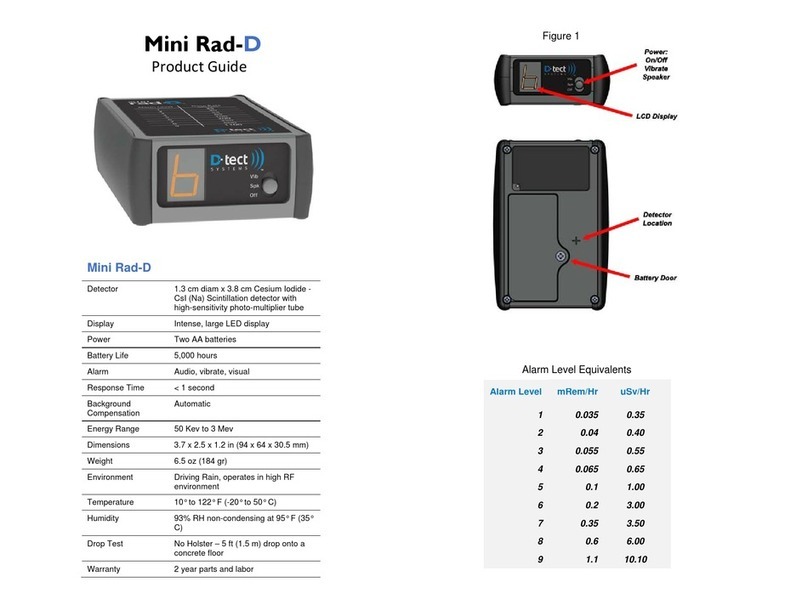
D-tect Systems Mini Rad-D Instruction Manual

D-tect Systems

D-tect Systems Mini Rad-D Instruction Manual

D-tect Systems Mini Rad-D User manual

D-tect Systems

D-tect Systems Mini Rad-D User manual

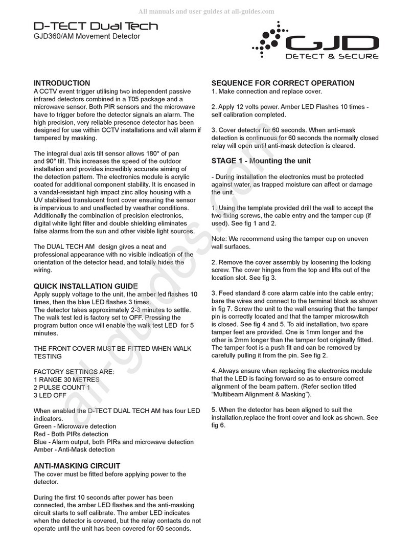
D-tect Systems D-TECT GJD360/AM User manual

D-tect Systems

D-tect Systems D-TECT GJD360/AM User manual

Popular Security Sensor manuals by other brands

Omron F3SG-*RR Series Quick installation manual

Omron

Omron F3SG-*RR Series Quick installation manual

Baumer 10P66YM manual

Baumer

Baumer 10P66YM manual

EVERLUX Excellence installation guide

EVERLUX

EVERLUX Excellence installation guide

Dahua ARD1611-W manual

Dahua

Dahua ARD1611-W manual

System Sensor OSI-RIE Series manual

System Sensor

System Sensor OSI-RIE Series manual

NOVOTEST UD1 operating manual

NOVOTEST

NOVOTEST UD1 operating manual

Niko 350-41650 Technical manual

Niko

Niko 350-41650 Technical manual

Trust AWST-6000 Important information

Trust

Trust AWST-6000 Important information

Viking K-1900-3 product manual

Viking

Viking K-1900-3 product manual

PCB Piezotronics Tourmaline ICP 138A26 Installation and operating manual

PCB Piezotronics

PCB Piezotronics Tourmaline ICP 138A26 Installation and operating manual

Heico STE Radiation Pager user manual

Heico

Heico STE Radiation Pager user manual

LEGRAND Celiane Series quick start guide

LEGRAND

LEGRAND Celiane Series quick start guide

BEA SBK-30R user guide

BEA

BEA SBK-30R user guide

Viega 1219.6 Instructions for use

Viega

Viega 1219.6 Instructions for use

DSC PG9905 installation guide

DSC

DSC PG9905 installation guide

Visonic NEXT PLUS MCW installation instructions

Visonic

Visonic NEXT PLUS MCW installation instructions

Roland R1000 series E20 manual

Roland

Roland R1000 series E20 manual

STEINEL professional Series operating instructions

STEINEL

STEINEL professional Series operating instructions

manuals.online logo
manuals.online logoBrands
  • About & Mission
  • Contact us
  • Privacy Policy
  • Terms and Conditions

Copyright 2025 Manuals.Online. All Rights Reserved.