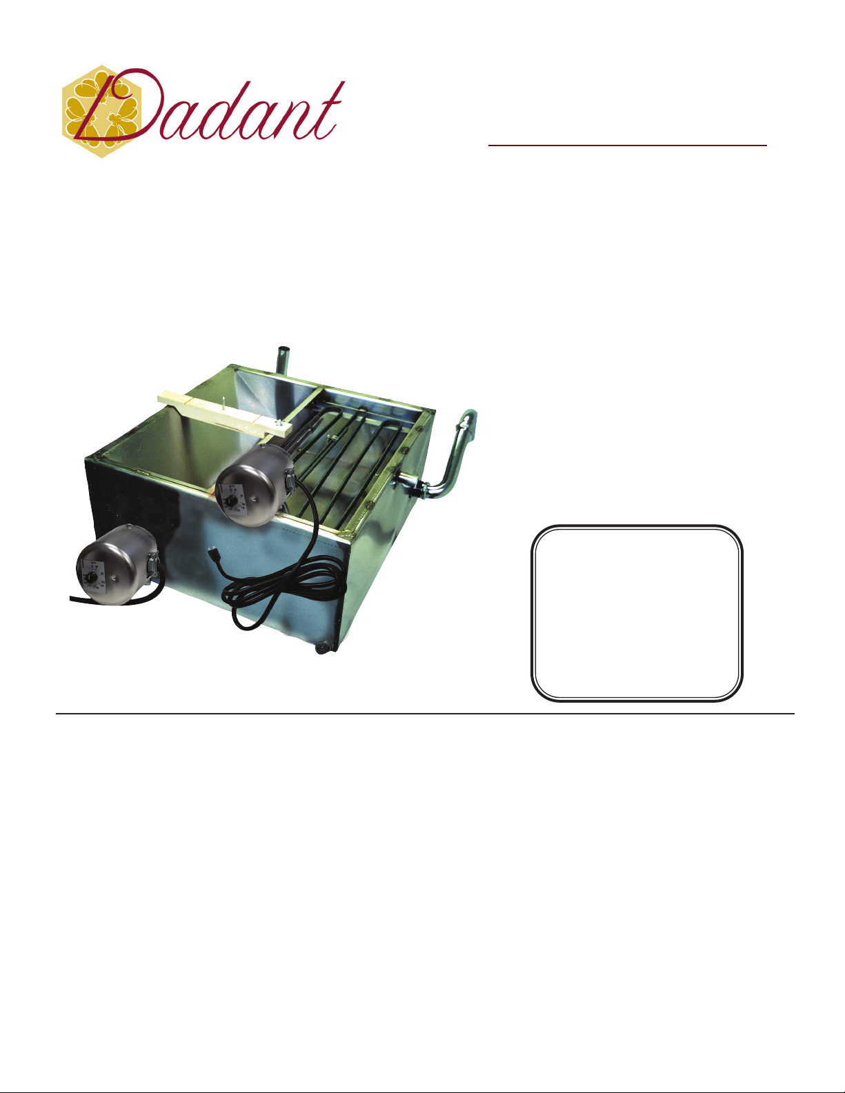
manuals.online logo
Brands
  1. Home
  2. •
  3. Brands
  4. •
  5. Dadant
  6. •
  7. Industrial Equipment
  8. •
  9. Dadant M005491 User manual

Dadant M005491 User manual

DADANT M005491MINI MELTER
CORPORATE OFFICE
51 S. 2nd Street, Hamilton, IL 62341
Ph. 217-847-3324 Toll Free 1-888-922-1293
Descripon/Funcon
Assembly
Operang Instrucons
Operaon
Precauons
The original Mini Melter was designed as an ecient cappings
processor for hand uncapping operaons. Uncap directly into
the unit on a sloped surface. Honey ows from one outlet while
beeswax ows from another outlet. Capping are processed in one
step—nothing extra to do. The cappings from over 200 pounds of
honey per hour were processed with original melter. Now the
unit has been waterjacketed to increase capacity and improve
control. The new waterjacketed Mini Melters have beer con-
trol for processing a smaller volume of cappings and have also
been used successfully under smaller capacity power uncappers.
The unit has now handled the cappings from over 300 pounds
of honey per hour. The unit comes complete with 1700 wa im-
mersion heater for water jacket. By warming the honey, faster
separaon of honey and cappings wax occurs, thus increasing
melng speed.
An Under grid Melter
Cappings slide down the sloped surface and oat up under
the heang coils. The honey seles to the boom never being
trapped in a hot area and remains “cool.”
Dadant Designed Melter Grid
Thermostacally controlled 120 volt all electric melng grid al-
lows precise control for each individual’s operaon.
Welded Tank Construcon
Made of 16 gauge (.0625 inches thick), type 304 san nish, food
grade stainless steel with MIG welds to provide superior strength
and highest quality inside and out.
Safety Precauons
The Dadant Mini Melter is an electrical heang device which
melts beeswax and requires constant safety precauons. Treat
this electrical heang device as you would any such device. It
does produce heat, therefore, if misused or abused, it can be a
hazard. However, for the use intended and by following normal
operang and important safeguards, it is a very safe unit. (See
Important Safeguards.) Keep small children and inexperienced
bystanders away from the Melter. Check to make sure all connec-
ons are secure and in good condion. Keep oor area in the vi-
cinity of the Melter clean and free of all obstacles. Be absolutely
sure nothing can fall into the pan causing splashing of hot wax.
Process Cappings in One Step
New Improved Design
Double Uncapping Area
Now 24’’ x 10’’
Electromelt Style Grid
Now It’s Like Its Big Brother
1800 Wa Melng Grid
Thermostat Control
2 Square Feet of Melng Surface
Dimensions: 37’’W x 30’’L x 11.5’’H
(Including Fings)
Descripon/Funcon
Chico, CA Branch
530-893-0921
1-877-332-3268
Fresno, CA Branch
559-495-0230
1-877-432-3268
Sioux City, IA Branch
712-255-3232
1-877-732-3268
Paris, TX Branch
903-784-6145
1-877-632-3268
Albion, MI Branch
517-629-2860
1-877-932-3268
Watertown, WI Branch
920-261-5363
1-877-232-3268
Williamsport, PA Branch
570-980-9831
1-877-532-3268
Chatham, VA Branch
434-432-8461
1-800-220-8325
High Springs, FL Branch
386-454-0237
1-877-832-3268
Frankfort, KY Branch
502-848-0000
1-888-932-3268
Dadant Mini Melter
The cappings resulting from frames of honey being
uncapped consist of honey, beeswax, and foreign mate-
rial. Dadant’s Mini Melter was designed to separate these
cappings into pure honey, quality (undamaged) beeswax
and foreign material (slum). When properly operated,
best honey experts are unable to determine which honey
is or is not melter honey, and wax tests show the highest
quality wax. The cappings melter is a great labor saving
piece of equipment as cappings are continually processed
while uncapping is being done. At the day’s end, all the
day’s cappings have been processed. The pure honey is in
storage, the extra fine beeswax is in cakes, and the slum
is barreled. No extra steps are required.
The cappings drop into the hopper area and flow
under the melting grid. When the cappings begin to flow
through the melter, separation of honey and wax occurs.
The honey, being the heaviest, settles to the bottom
of the tank and the wax particles and foreign material
float on the honey. On those waterjacketed units, the
heat from the warm water in the waterjacket, speeds
this separation process. As the wax particles float on the
honey, they come in contact with the melting grid and
are melted. A pool or layer of melted wax entirely covers
the melting grid. As the cappings float to the surface a
great bulk of the wax particles are now melted by com-
ing into contact with this layer of melted wax. As the
quantity of melted wax increases, it flows out of a wax
outlet. Meanwhile, the honey that has been separating
from the wax flows along the bottom of the tank, under
the honey baffle, and flows out of the melter through an
adjustable honey outlet. This honey outlet maintains the
honey level in the tank, thereby holding the unmelted
wax particles up against the melting grid as they float
on the honey. As the unmelted wax particles continue
to rise, the foreign material (slum) is carried upward and
collects on top of the unmelted cappings just below or in
the melted wax. The slum is periodically removed (usually
once an hour) with the larger perforated screen that was
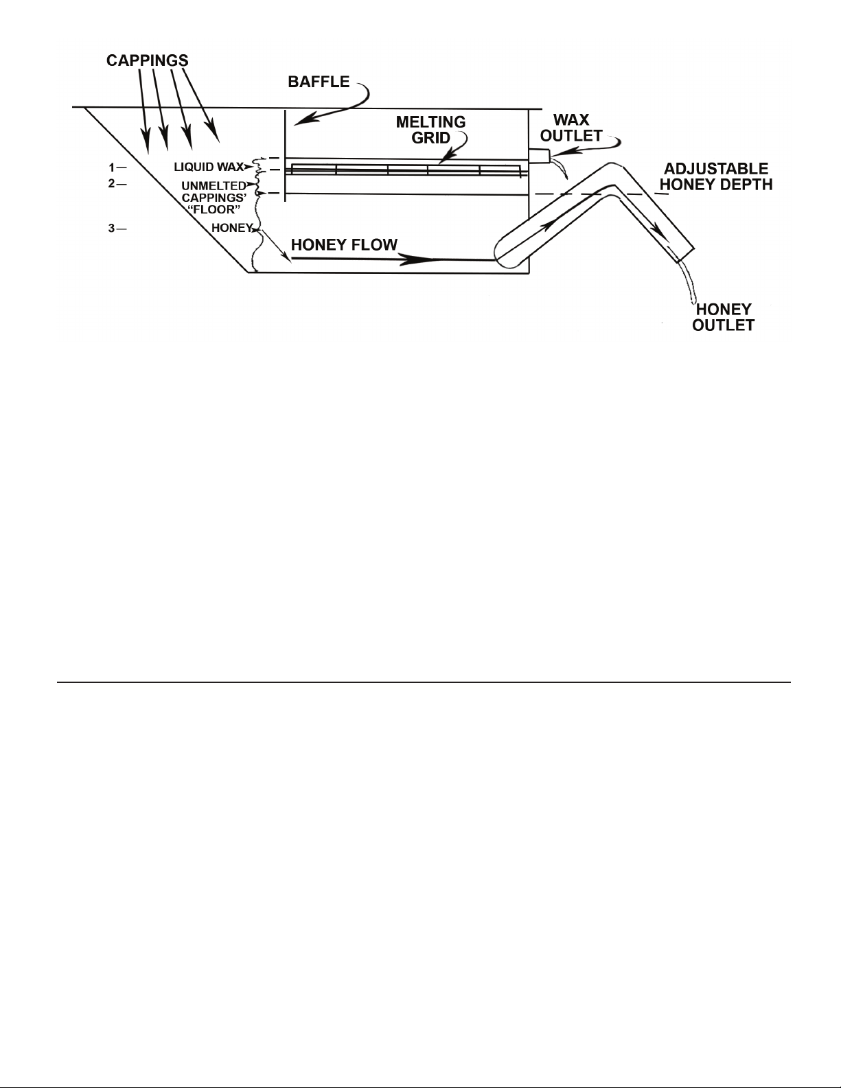
supplied with the Mini Melter. Refer to the diagram and
please note the liquid levels and visualize how the setting
of the adjustable honey tube is the key to maintaining
proper operation.
For most operating conditions, the honey outlet tube
is adjusted to a level that allows honey to flow out of the
tube when honey level in the tank is 1’’ below the bot-
tom of the melting grid. This 1’’ allows for the layer of
unmelted cappings to be maintained which in turn holds
the foreign material (slum) up thus preventing the slum
stain from filtering through and discoloring the honey.
During operation, it is important to maintain this “floor”
of unmelted cappings. This floor depth may be “felt”
by pushing a thin board between the melting grid bars
down through the liquid levels and “feeling” the depth
of unmelted cappings by noting the resistance to pushing
the board. The electric grids make heat control extremely
easy as the electric grid has a very sensitive thermostat
control that is easily adjusted. The heat supply should be
regulated so as to keep a “floor” of unmelted cappings
under the hot liquid wax yet keep the bottom of the tank
from plugging with cappings. A continuous steady flow of
cappings into the melter helps any melter work more eas-
ily. Jumpy operations are not as good, but the electric grid
makes control of the heat precise and easy.
(Prolonged application of heat with no cappings flow
can result in losing the “floor” of unmelted cappings
allowing the slum to pass down through the honey and
darken it. Excessive heat can also darken beeswax and
eventually honey.)
Assembly
1. Completely unpack the Mini Melter and idenfy:
1 melng grid,
1 uncapping cross bar,
1 small perforated screen,
1 large perforated screen,
1 adjustable honey outlet assembly,
1 1700W immersion heater and
1 elbow/nut assembly
2. A third screen should be located in the honey bae/
honey outlet of the tank.
3. Assemble the adjustable honey outlet tube as shown in
the diagram and aach to the tank.
4. If uncapping with a hand knife, aach the uncapping
cross bar to the exposed edges of the tank and tank baf-
e respecvely. (Bar is not needed if power uncapping.)
5. Place grid in tank on grid rests (See photo on cover.)
6. Install small perforated screen over wax outlet. (This
screen prevents foreign material from owing through
wax outlet.)
7. The large perforated screen is for slum removal.
8. In the tank water drain outlet, a 1’’ plug has already
been installed.
9. Using a good pipe thread compound, install the immer-
sion heater in the 1’’ female tank port.
10. The elbow/nut assembly with gasket is the water ll
pipe. Aach it to the 1 ½’’ pipe thread nipple extending
from the tank and ghten in a vercal posion.
Operaon
By allowing the hot liquid wax to accumulate on top of
the melting grid with a temperature of 170 - 210° F, the
liquid wax actually does most of the melting. The honey
never contacts the hot melter grid, but passes through
the melter along the bottom of the tank. As a general
rule, the honey flowing out of the melter should not
exceed 125° F and may be as low as 95° F. A greater
depth (floor) of unmelted cappings is obtained by push-
ing down the honey outlet pipe. This lowers the honey
level in the tank leaving more room on top of the honey
for unmelted cappings. With these new waterjacketed
models, honey temperature can be precisely controlled
by regulating water temperature. To flow all the hot
liquid wax out of the tank at the end of the day’s work,
raise the honey overflow pipe up about one inch approxi-
mately an hour before uncapping stops, or add honey to
bring up the honey level and flow the wax out of the unit.
By occasionally noting the “floor” of cappings while
uncapping, the relationship between proper heat set-
tings and good melter operation will be quickly under-
stood. It will also be noted that a rather wide range
exists thus making melting control very easy. Should
uncapping be stopped for an extended period of time,
the melting grid and water immersion heater thermo-
stats may be turned down to prevent the loss of the
“floor” of unmelted cappings. Conversely, if uncapping
is at a very rapid pace, the thermostats may be set at
higher temperatures to increase melting capacity. By
noting approximate honey and wax temperatures and
the “floor” of cappings, ultimate melter operation may
be achieved and then maintained with only minimal
attention. Being observant is the greatest asset to oper-
ating any piece of equipment, especially a melter.
Operang Instrucons
1. On water jacketed models, always be sure the immer-
sion heater in the water jacket is covered with water.
Check Daily. Set the immersion heater to approxi-
mately 140° F and let the
water begin warming.
2. Oponal-To prevent cappings from sliding under the
honey bae during empty tank start-up, pour enough
clean honey in the tank to obtain approximately a 4’’
depth of honey in the boom of the tank.
3. Adjust the honey outlet to a level that would allow
honey to ow from the unit at a level approximately
1’’ below the boom of the melng grid.
4. Begin uncapping and uncap unl the cappings begin
to touch the melng grid.
5. Turn on your melng grid and set thermostat to about
200° F to begin the melng process.
6. Connue to uncap and build a layer of melted wax. This
accumulaon (depth) of melted wax will do most of the
melng and honey will not contact the heang coils.
Honey temperature coming out of the melter should
be low enough to not darken the honey. Specic tem-
perature cannot be given as nectar source is a factor in
determining darkening temperature. As a general rule,
honey temperature should not exceed 125° F. The hon-
ey outlet tube usually works best at ¾’’ to 1’’ below the
boom of the melter grid elements and can be adjusted
slightly for best operaon. As the melter approaches full
operaon, honey will ow through the adjustable honey
outlet tube and wax will ow from the wax outlet.
7. The key to successful operaon of the Cappings Melter
is to keep a oor of unmelted cappings under the liquid
wax that is oang about the grid. A layer of slumgum
will develop between liquid wax and the layer of un-
melted cappings with the honey remaining on the
(Connued On Next Page)
Replacement Parts for M00549 Mini Melter
Part Number` Descripon
04-54921 Electric Grid
04-54906A Wooden Cross Bar w/lag screw
03-50222 1-1/2” Quarter Bend
Part Number` Descripon
03-50223 1-1/2” x 6” Slip Joint Elbow
04-54924 Hand Slum Rake perf. aluminum
cooler boom of the melter. The oor of unmelted
cappings under the hot liquid wax is necessary to
hold up the slumgum accumulaon as it melts. The
slumgum accumulaon should be scraped from the
oor of unmelted cappings from me to me which
will help speed up the melng. A perforated hand
tool (slum rake) is provided to assist you. Some nd it
easiest to remove the melng grid, remove the slum,
and replace the grid before the melted wax solidies.
The cappings oor can be tested periodically as de-
scribed in the operaon secon. If there is no oor
of unmelted cappings, cut back on the heat supply by
turning the thermostat o, or speed up the volume of
cappings entering the melter. If the incoming supply
of cappings decreases, reduce the heat.
8. When uncapping is nished for the day, let the melter
“catch up” and then turn o the melng grid and wa-
ter jacket immersion heater. (To quicken start-up on
the water jacketed model, the water jacket immersion
heater may be turned on an hour or two before un-
capping begins. Be sure enough water is in the tank.)
9. Thermostacally controlled electric heaters provide
fast start-up (usually 20-30 minutes). Local weather
condions and the moisture content of the honey
may indicate the best method of operaon.
In summary, the Mini Melter can be easily and precise-
ly controlled. Honey temperature coming out of the
melter should be 90°-120° and not over 125° F. Honey
temperature is controlled by water temperature on the
water jacketed models. Increasing water temperature
increases melng capacity because honey/wax separa-
on is faster. Melng grid temperature determines the
beeswax quality and maintains the “oor” of cappings
which oats the slum. Increasing melng grid temper-
ature increases the melter capacity and vice-versa. Set
grid temperature to corresponding uncapping speed.
The thickness of the “oor of unmelted cappings” in-
dicates the correctness of grid temperature. A rather
wide latude exists. Frequent slum raking and removal
speeds melng. Monitoring honey temperature, while
learning to use the Mini Melter speeds the learning
process and increases understanding rapidly. Aer the
melng process is understood and inial visual refer-
ences are made, the melter can easily be operated
with lile aenon required.
Precauons
Eleven Important Precauons
1. Read all instrucons.
2. Always unplug the unit from the outlet when not in
use and before cleaning.
3. Never have the unit unaended when plugged in or
in operaon.
4. Hot wax is always dangerous. Keep children away
from unit during operaon and keep oors, bench-
es, and shelves in the area free from arcles.
5. Never aempt to move the unit while wax is liquid.
Splashed melted wax will cause burns.
6. Always use the unit as specied. Never use unit for
other than intended use. Any use not recommend-
ed may cause hazards.
7. Never remove the clamps holding the heat sensor to
the melng grid. Overheang could occur.
8. Do not touch the hot grid surfaces.
9. Do not allow the power cord to get pinched, touch
hot surfaces or lay on the oor in a traveled area.
10. Never operate any electrical device with a damaged
cord or plug.
11. Keep foreign material such as rags etc., out of the
melter pan.
USA Parts Orders Only

Other Dadant Industrial Equipment manuals

Dadant Fill Master M006262 User manual

Dadant

Dadant Fill Master M006262 User manual

Dadant M005531 User manual

Dadant

Dadant M005531 User manual

Popular Industrial Equipment manuals by other brands

Graco President K Series Instructions-parts list

Graco

Graco President K Series Instructions-parts list

ABB HT582771 Operation manual

ABB

ABB HT582771 Operation manual

ATS PAV3 instruction manual

ATS

ATS PAV3 instruction manual

DRIESCHER-WEGBERG LDTM 24 kV Addition to Operating Manual

DRIESCHER-WEGBERG

DRIESCHER-WEGBERG LDTM 24 kV Addition to Operating Manual

Maxcess FIFE-500 Quick start setup

Maxcess

Maxcess FIFE-500 Quick start setup

Dupont IntegraTec Ultrafiltration T-Rack Manifold II P... Assembly instructions

Dupont

Dupont IntegraTec Ultrafiltration T-Rack Manifold II P... Assembly instructions

Judo FERROCLEAN Installation and operating instructions

Judo

Judo FERROCLEAN Installation and operating instructions

Icar SUPERriphaso instruction manual

Icar

Icar SUPERriphaso instruction manual

Siemens NEC Article 409 Reference manual

Siemens

Siemens NEC Article 409 Reference manual

Universal 5588 Series instruction manual

Universal

Universal 5588 Series instruction manual

eks pe-light-M-COAX manual

eks

eks pe-light-M-COAX manual

Shini SG-36 Series manual

Shini

Shini SG-36 Series manual

Graco TI12552a installation instructions

Graco

Graco TI12552a installation instructions

Strobel VEB100-3 Mechanic's instructions

Strobel

Strobel VEB100-3 Mechanic's instructions

Wavetronix Click 500 Series user guide

Wavetronix

Wavetronix Click 500 Series user guide

Sagola PREMIUM 30 instruction manual

Sagola

Sagola PREMIUM 30 instruction manual

BGU HBG 100-2 user manual

BGU

BGU HBG 100-2 user manual

ABB TPL76-C35 Operation manual

ABB

ABB TPL76-C35 Operation manual

manuals.online logo
manuals.online logoBrands
  • About & Mission
  • Contact us
  • Privacy Policy
  • Terms and Conditions

Copyright 2025 Manuals.Online. All Rights Reserved.