Daekyung DTR-300N User manual

DAEKYUNG TECH & TESTERS Mfg. CO.,LTD
- 1 -
대경테크주식회사
DAEKYUNG TECH & TESTERS Mfg. CO.,LTD
ADDRESS : 118-10, 688-10, GOJAN-DONG, NAMDONG-GU
INCHEON-CITY, KOREA
PHONE : 82-32-822-5511
FAX : 82-32-821-4580
URL : http://www.dktt.co.kr or www.idtnt.com
Operation Manual for
Rockwell Hardness Tester
[ MODEL : DTR-300N ]
Model : DTR-400N

DAEKYUNG TECH & TESTERS Mfg. CO.,LTD
- 2 -
Greetings
Thanks for purchasing our product! Please use the product
correctly after first reading this operation manual carefully.
With gratitude for your selection, all of the employees promise to
do our best to continue to produce more advanced testers that
compete with the world’s most famous testers.
Daekyung
Tech
&
Testers
Co., Ltd

DAEKYUNG TECH & TESTERS Mfg. CO.,LTD
- 3 -
-
Table of Contents
-
1. Product Overview P.4
2.
Features
P.4
3. Specifications P.4~5
4. Part Names P.5
5.
Names and Functions of Digital Display Part
P.6~10
6. Installation and Test procedures P.10~11
7.
Cautions
P.11~12
8. Standard Accessories P.12
9.
Others
9.1 Reference Table 1. P.13
9.2 Reference Table 2. P.14
9.3 Reference Table 3. P.15
10. Hardness Comparison Table 1
Copy

DAEKYUNG TECH & TESTERS Mfg. CO.,LTD
- 4 -
1. Product Overview
This tester is easy to use and supports high accuracy. Its
operating principle is to measure by using the depth difference
of the test traces caused by the initial load and the test load.
At this time, 10 kgf is applied to the initial load, and the test
load is determined by increasing the load. This Rockwell
hardness tester can measure even nonmetal materials like
plastics as well as soft/hard metal materials.
2.
Features
2.1 The tester uses the automatic motor operation method that
has no personal error while measuring.
2.2 The indicating lamp turns on during the test. It is easy to
construct a test environment.
2.3 The load hold time can be controlled directly.
2.4 Relatively soft/hard materials can be measured exactly.
2.5 The hardness value is displayed in the digital display part to
enable reading the value directly.
2.6
Test trace remains fine, and it does not influence the product test.
2.6 Measurement range is wide.
3.
Specifications
3.1
Load
3.1.1
Standard Load
:
10
kgf

DAEKYUNG TECH & TESTERS Mfg. CO.,LTD
- 5 -
4.1 ①
Digital Display Part
4.2 ②
Lighting
LA
M
P
4.3 ③
Indenter (Diamond cone/Steel Ball)
4.4
④
Anvil
4.5 ⑤
Screw
4.6 ⑥
Screw
Handle
4.7 ⑦
Menu Setup Key
4.8 ⑧
Main
S/W
4.9 ⑨
Cord
Connector
4.10 ⑩
RS-232C & USB Port
4.11 ⑪
Equipment Cover
4.12 ⑫
Dead Weight Adjustment Handle
⑪
①
⑦
③ ② ⑫
④ ⑧
⑤ ⑩
⑥ ⑨
3.1.2
Test Load
: (60, 100, 150) kgf
3.2
Vertical Test Gap
: 210 mm
3.3
Maximum Specimen Diameter
: ø 250
4. Part Names

DAEKYUNG TECH & TESTERS Mfg. CO.,LTD
- 6 -
HRC, HRA, HRB,
HRD
HRE,
HRF,
HRG,
HRH
HRK,
HRL,
HRM, HRP
HRR,
HRS,
HRV
◉ USE ↑ ↓ ← →
◉ ENTER :
Close after Setting
◉ RESET : Exit
Ex) Enter after selecting HRC
5. Names and Functions of Digital Display Part
5.1 Selected Balance Weight
5.2
Selected Hardness Unit and Cone Display
①
5.3
Strain Display
②
5.4
Display of normal test standby or dead selection error
③
5.5 MENU : All Menu Setting
④
5.6 ∅
:
Input of Spherical or Cylinder Shape Specimen Size
5.7
Reset
:
G
A
U
G
E
Zero Setting
5.8
Enter, Arrow: Buttons for Menu Mode
⑧
⑤ ⑥ ⑦ ⑧
5.9
Manu
⑤
Function
5.9.1 Scale (
SCALE)
:
Change and Setting of Hardness Unit
5.9.2
Load Maintenance (D. Load Sec): Load applying time by the dead weight
1)
Set by using the Up/Down (↑,↓) arrow keys. (Increase/decrease second by second)
2)
Press the Enter key after setting.
5.9.3
Reading Standby (D. Read Sec): Set the standby time before reading
1)
Set by using the Up/Down (↑,↓) arrow keys. (Increase/decrease second by second)
2)
Press the Enter key after setting.
5.9.4
Minimum HRC/0.0 (miN HRC 0.0): Error message when out-of-minimum tolerance
1)
Set by using the Up/Down/Left/Right arrow (↑,↓,←,→) keys.
2)
Press the Enter key after setting.
(Initial Value
:
0.0
miN)

DAEKYUNG TECH & TESTERS Mfg. CO.,LTD
- 7 -
5.9.5
Maximum HRC/0.0 (maX HRC 0.0): Error message when out-of-minimum tolerance
1)
Set by using the Up/Down/Left/Right arrow (↑,↓,←,→) keys.
2)
Press the Enter key after setting.
(Initial Value
:
0.0
maX)
5.9.6
Continuous Function (Data Size 200): Maximum Test Count
1) Initial Value
:
N
=
0
(Maximum Setting
:
N
=
200)
2)
Ex) Setting Value: For N = 5 –Mean and Standard Deviation f(S.D.)or the measurement of five times
5.9.7 View Result
(
View
S.D
)
:
Mean and S.D. for test count
5.9.8
Data Initialization (Data Initial): Test Data Initialization (Deletion)
5.9.9
Language (Language Eng/Kor): Language selection (English/Korean)
5.9.10 Load Unit
(
A.
Force
Unit
kgf/N
)
:
Load display unit
5.9.11
Serial Output (B. Serial Out OFF/OnK/OnA): Printer output (Printer Optional item)
1)
For
OFF
:
No print
◉
Execute after the hardness measurement result value is displayed
- Ex
)
For
HRC
99.2
2)
For
OnK
①
When pressing the right arrow key (
▶):
The current hardness value is printed (One time)
-
003 : HRC 099.20 Output
Test count Hardness value
②
When pressing the left arrow key (
◀):
The current hardness value is printed
(one time):
003: HRC 099.20 (Test Count:Print of the hardness value)
Total No: 003 (Print of the measured counts in the specified count)
S.D Value: 000.50 (Print of the current hardness standard deviation)

DAEKYUNG TECH & TESTERS Mfg. CO.,LTD
- 8 -
3)
For
OnA
①
When pressing the right arrow key (
▶):
The current hardness value is printed (one time)
:
Test Number : (
Manual input of Test
No.
)
Test Date
:
(
Manual input of test date
)
Operator
:
(
Manual input of test operator
)
Specimen :
(Manual input of specimen mark)
Remarks :
(
Manual input of remarks
)
001 : HRC 099.30 (
Test Count: Print of Hardness value)
②
When pressing the left arrow key (
◀):
The currently measured hardness value is printed
:
Test Number : (
Manual input of test No.)
Test Date
: (
Manual input of test date
)
Operator
:
(
Manual input of test operator
)
Specimen : (
Manual input of specimen mark
)
Remarks :
(
Manual input of remarks
)
001 : HRC 099.30 (
Test Count: Print of Hardness value
)
002 : HRC 099.30 (
Test Count: Print of Hardness value
)
Total No
: 002 (
Print of total test counts
)
Avr Value : 098.30 (
Print of total hardness mean value)
S.D Value : 000.30 (
Print of total standard deviation
)
5.9.12
Backlight (C. Back-Light): Setting of backlight (unit: sec.) – Up to 200 sec can be selected.
5.9.13
Calibration Mode (D.Calibration OFF/C-1,C-2): Calibration mode (1: Indirect, 2: Direct), Set as Off usually.

DAEKYUNG TECH & TESTERS Mfg. CO.,LTD
- 9 -
◉ ← → : Adjust digit numbers
◉ ↑ ↓ : Adjust selected digit numbers
◉ Enter : Confirm
◉ Reset
: Cancel
◉ ← → : Adjust digit numbers
◉ ↑ ↓ : Adjust selected digit numbers
◉ Enter : Confirm
◉ Reset
: Cancel
5.9.14
Debug Mode Non (E.Debug Mode:Print of the system status): (Inhibition of use), Initial setting value Non
5.9.15
Exit (
F.
Exit
)
:
Exit the
Manu
5.10 ∅
Function
5.10.1
R. Cylinderical: Enter a radius (R) value for a cylinder-shaped specimen.
1)
Initial value
:
R
=
0.00
mm
2)
ex) Enter a radius value, R10, when the specimen has the radius of Ø
Press the Enter key after setting as R = 10.00 by using the Up/Down/Left/Right arrow keys (↑,↓,←,→)
3)
Maximum input range
:
R
=
19.99
mm
5.10.2
D Spherical: Enter a diameter (Ø) value for a spherical-shaped specimen.
1)
Initial Value
:
D
=
0.00
mm
2)
Ex) Enter a diameter value, Ø 20, when the specimen has the diameter of Ø 20.
Press the Enter key after setting as D = 20.00 by using the Up/Down/Left/Right arrow keys (↑,↓,←,→)
3)
Maximum input range
:
D
=
25.99
mm
5.10.3 Exit : Exit the menu.
5.11 Others
5.11.1
If R is entered, D is set as Ø. If D is entered, R is set as Ø. At this
time, only one of the above cases is valid.

DAEKYUNG TECH & TESTERS Mfg. CO.,LTD
- 10 -
2. Wait Hold Time ⇨ 3. Load Weight : Motor operation
⇨
6. Wait Load Time :
→ D. Load Time Setting Value
⇨ 7. Remove Weight :
Motor operation
⇨
8. Wait Read Time :
→ D. Read Time
Setting Value
⇨
Display of Hardnes Value
5.11.2
If Øhas been entered after the test, the calibration value is displayed.
6. Installation and Test Procedures
6.1
The tester should be installed in the stable place without dust, humidity, or vibration.
6.2
After installing the machine on the strong support, make a hole for the test at the diameter of 90 mm and the
depth of 160 mm on the support located in the screw lower part. This makes it possible to lower the screw.
6.3
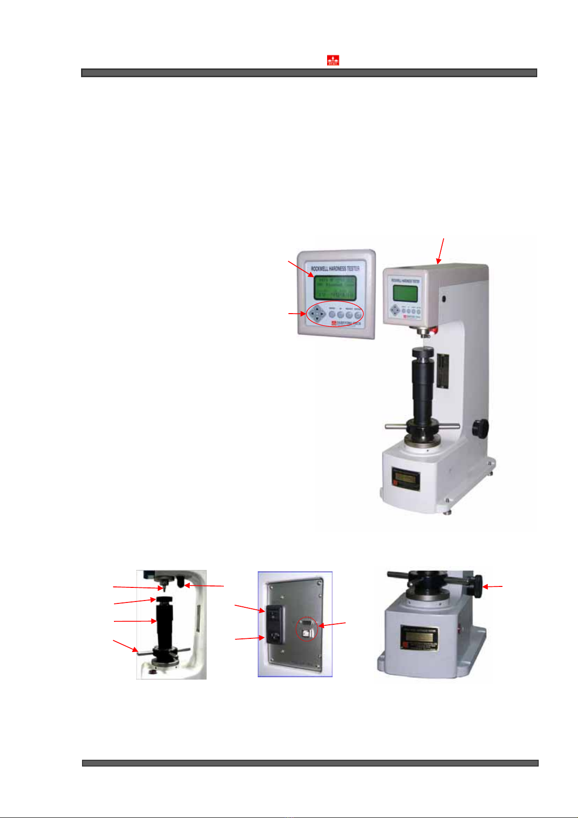
After installing the machine on the support, unpack the machine and align the level to prevent the
machine from shaking. To align the level, unfasten the equipment cover (⑪) by using a hexagonal
wrench and align the dead weight and the dead weight support in line by using a level adjustment screw.
6.4
Clean the contact surface of the Anvil (④), remove foreign materials and oil, and then insert the anvil to the machine.
6.5
Select a scale appreciate for the specimen and insert a diamond cone or a steel
ball indenter matching with the scale. Set the dead weight (60, 100, 150 kgf)
adjustedfor the scale by using the dead weight adjustment handle (⑫).
6.6
Turn on the Main S/W (⑧). At this time, check if the main power is turned on. If
not, connect the Cord Connector (⑨). The lighting LAMP (②) is turned on.
6.7
Put the specimen on the Anvil (④) and turn the Screw Handle (⑥) in the right
direction. If the the mark (>) of the Digital Display part is progressed to the end
of >>>>>>>> (Gauge 2.900 mm or more), the test is started along with the
‘beep’ buzzer sound as the lighting lamp (②) is turned off.
※ The procedure is as follows:

DAEKYUNG TECH & TESTERS Mfg. CO.,LTD
- 11 -
6.8
If the test is started, the load is applied and released automatically. If the test is
completed, read the hardness value of the Digital Display part (①).
Measured Hardness
Mean Value
Measured Counts
Standard Deviation
User Setting
:
Measurement Setting Counts
Conversion to another hardness value: Convert into another
hardness value by using the Up/Down arrow keys (↑,↓).
6.9
Extract the specimen, turning the Screw Handle (⑥) to the right and continue the
next test. At this time, the Digital Display part (①) returns to the initial screen and
the Lighting Lamp (②) is turned on.
7. Cautions
7.1 Do not disassemble or modify this tester. For the repair,
contact our customer service team.
7.2 This tester operates on
AC
220V. Do not touch with wet hands.
To do so may cause trouble or electirc shock.
7.3 If water enters in the tester, disconnect the power (AC 220V)
quickly. Contact your dealer or our customer service.
7.4
To transport the machine, first turn off the machine and then move. For
the installation procedure after transporting, refer to Paragraph 6.3..
7.5
For the test, process the contact surface roughly between a specimen and the Anvil to make it flat.

DAEKYUNG TECH & TESTERS Mfg. CO.,LTD
- 12 -
7.6
Install a specimen and the indenter vertically and avoid getting the trace surface rough.
7.7
For the selection of a scale appreciate for the specimen, refer to Reference table 1.
7.7.1 Round Bar
:
V
Anvil (big-sized
)
7.7.2 Small Pin Type
:
V
Anvil (small-sized)
7.7.3
For step-shaped contact surface (not plane): Spot Anvil
7.7.4
For large-sized specimen: 200 mm Testing Table - Optional item
7.8 Replace the anvil or the specimen with care to prevent from
damage by shock.
7.9 For a cylinder-shaped specimen, refer to Reference table 2.
8. Standard Accessories
8.1 C Scale Hardness-Standard Specimen
:
1 ea
8.2
B Scale Hardness-Standard Specimen
:
1ea
8.3
Dead Weight
(60,
100,
150
kg):
1 ea
8.4
Diamond Cone
:
1 ea
8.5
Stee1 Ball Indenter
(1/16")
:
1 ea
8.6
Spare Indenter
(1/16")
:
5 ea
8.7
Spot
Anvil
(Ø10)
:
1 ea
8.8
Plane Anvil
(Ø63)
:
1 ea
8.9
V
Anvil
(Big-sized)
:
1 ea
8.10
V
Anvil
(Small-sized)
:
1 ea
8.11
Tester Cover
:
1 ea
8.12
P.P
Box
(Tool
Box)
:
1 set

DAEKYUNG TECH & TESTERS Mfg. CO.,LTD
- 13 -
Scale Indenter Std. Load
(kgf) Test Load
(kgf) Hardness
Expression Application Scope
A
D
C
Cone line-tip angle 120±30°
Diamond indenter that the
curvature radius of the
spherical surface is
0.2 ±0.02mm
10 60
100
150 100-500h
Sintered Carbide
Carburizing Steel
Pearlitic Malleable Iron
Carbon Steel
F
B
G
Name:
1/16"
Steel Ball
(Diameter:
1.588mm)
10 60
100
150 130-500h
Copper Alloy
Aluminum Alloy
Malleable Iron
Soft Steel
H
E
K
Name:
1/8"
Steel Ball
(Diameter:
3.175mm)
10 60
100
150 130-500h
Powder Alloy
Aluminum Alloy
Magnesium Alloy
Grindstone
L
M
P
Name:
1/4"
Steel Ball
(Diameter:
6.350mm)
10 60
100
150 130-500h Plastics
Light Alloy
Lead
R
S
V
Name:
1/2"
Steel Ball
(Diameter:
12.70mm)
10 60
100
150 130-500h Plastics
Light Alloy
9.1 Reference Table
1. Rockwell Hardness Scale

Measured
Hardness
Cylinder Diameter
1/4"
(6.4mm) 3/8"
(10mm) 1/2"
(13mm) 5/8"
(16mm) 3/4"
(19mm) 7/8"
(22mm) 1 "
(25mm) 1 1/4"
(32mm) 1 1/2"
(38mm)
Calibration value (Actual hardness = Measured hardness + Calibration value)
20 6.0 4.5 3.5 2.5 2.0 1.5 1.5 1.0 1.0
25 5.5 4.0 3.0 2.5 2.0 1.5 1.0 1.0 1.0
30 5.0 3.5 2.5 2.0 1.5 1.5 1.0 1.0 0.5
35 4.0 3.0 2.0 1.5 1.5 1.0 1.0 0.5 0.5
40 3.5 2.5 2.0 1.5 1.0 1.0 1.0 0.5 0.5
45 3.0 2.0 1.5 1.0 1.0 1.0 0.5 0.5 0.5
50 2.5 2.0 1.5 1.0 1.0 0.5 0.5 0.5 0.5
55 2.0 1.5 1.0 1.0 0.5 0.5 0.5 0.5 0
60 1.5 1.0 1.0 0.5 0.5 0.5 0.5 0 0
65 1.5 1.0 1.0 0.5 0.5 0.5 0.5 0 0
70 1.0 1.0 0.5 0.5 0.5 0.5 0.5 0 0
75 1.0 0.5 0.5 0.5 0.5 0.5 0 0 0
80 0.5 0.5 0.5 0.5 0.5 0 0 0 0
85 0.5 0.5 0.5 0 0 0 0 0 0
900.500000000
DAEKYUNG TECH & TESTERS Mfg. CO.,LTD
- 14 -
9.2
Reference Table
2.
Calibration value when a cylinder-shaped specimen is tested as C, A, D scales

Measured
Hardness
Cylinder Diameter
1/4"
(6.4mm) 3/8"
(10mm) 1/2"
(13mm) 5/8"
(16mm) 3/4"
(19mm) 7/8"
(22mm) 1 "
(25mm)
Calibration value (Actual hardness = Measured hardness + Calibration value)
0 12.5 8.5 6.5 5.5 4.5 3.5 3.0
10 12.0 8.0 6.0 5.0 4.0 3.5 3.0
20 11.0 7.5 5.5 4.5 4.0 3.5 3.0
30 10.0 6.5 5.0 4.5 3.5 3.0 2.5
40 9.0 6.0 4.5 4.0 3.0 2.5 2.5
50 8.0 5.5 4.0 3.5 3.0 2.5 2.0
60 7.0 5.0 3.5 3.0 2.5 2.0 2.0
70 6.0 4.0 3.0 2.5 2.0 2.0 1.5
80 5.0 3.5 2.5 2.0 1.5 1.5 1.5
90 4.0 3.0 2.0 1.5 1.5 1.5 1.0
100 3.5 2.5 1.5 1.5 1.0 1.0 0.5
DAEKYUNG TECH & TESTERS Mfg. CO.,LTD
- 15 -
9.3
Reference Table
3
.
Calibration value when a cylinder-shaped specimen is tested as B, F, G scales
Table of contents