GENERAL ENGINE INFORMATION 1A – 3
DAEWOO T-154 BL2,3
OIL PRESSURE TEST (CONT’D)
Step
ÜÜÜÜÜÜÜÜÜÜÜÜÜÜÜÜÜ
ÜÜÜÜÜÜÜÜÜÜÜÜÜÜÜÜÜ
Action
Value(s)
Yes
No
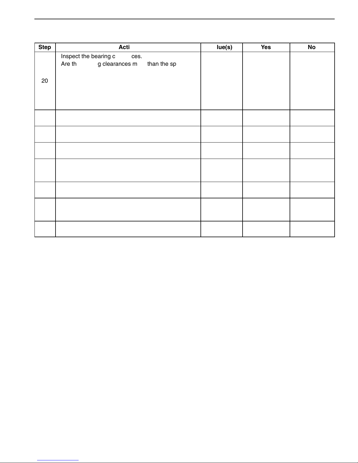
20
Inspect the bearing clearances.
Are the bearing clearances more than the specified
values?
Crankshaft
0.005 mm
(0.002 in.)
Connecting
Rod
0.019 X
0.070 mm
(0.0007 X
0.0027 in.) Go to Step 21 Go to Step 22
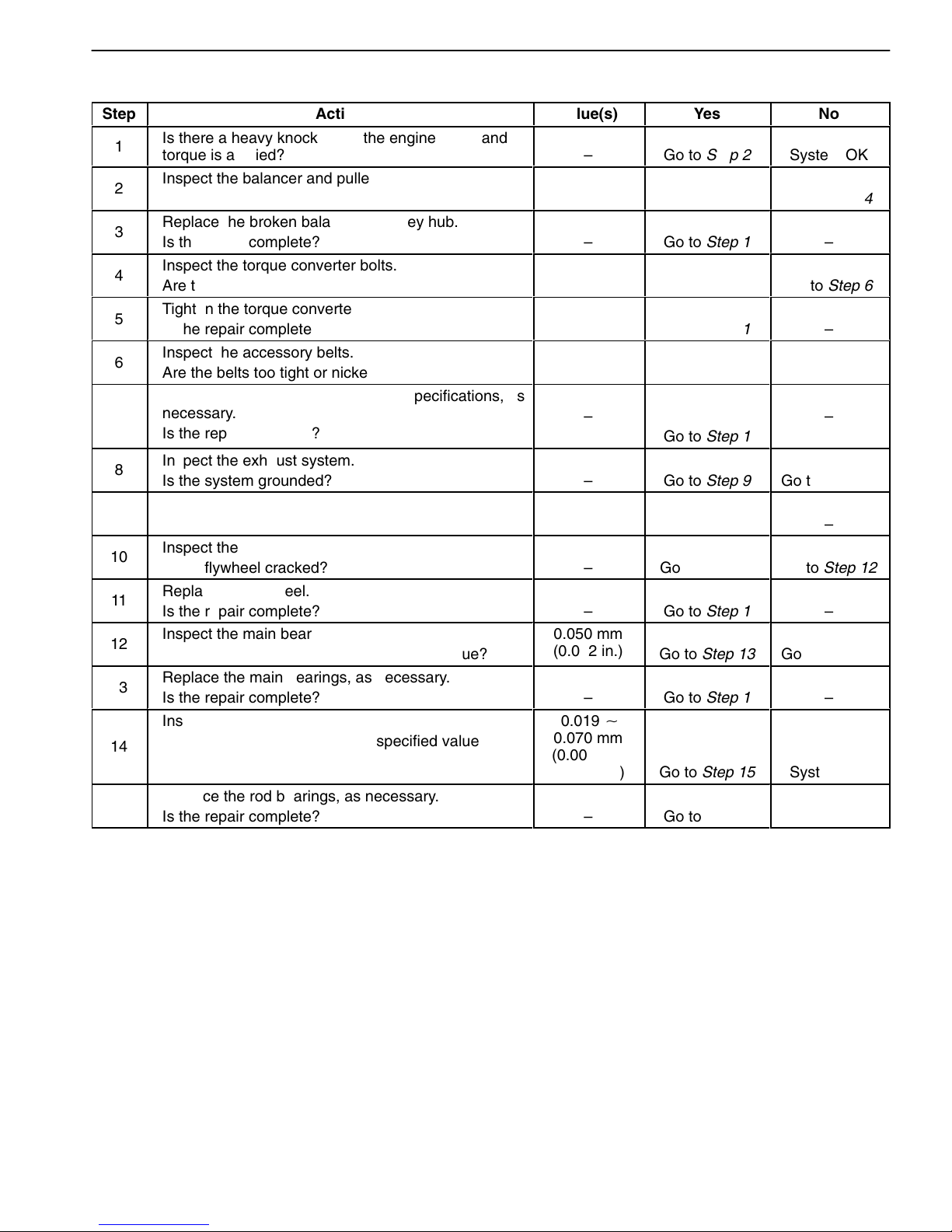
21 Replace the bearing, if necessary.
Is the repair complete? –Go to Step 1 –
22 Inspect the oil galleries.
Are the oil galleries cracked, porous or plugged? –Go to Step 23 Go to Step 24
23 Repair or replace the engine block.
Is the repair complete? –Go to Step 1 –
24
Inspect the gallery plugs.
Are any of the gallery plugs missing or installed
improperly?
–
Go to Step 25 Go to Step 26
25 Install the plugs or repair them, as necessary.
Is the repair complete? –Go to Step 1 –
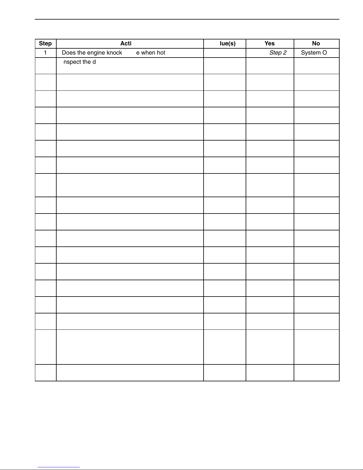
26
Inspect the camshaft.
Is the camshaft worn or is there evidence of poor
machining?
–
Go to Step 27 System OK
27 Replace the camshaft.
Is the repair complete? –Go to Step 1 –
OIL LEAK DIAGNOSIS
Most fluid oil leaks are easily located and repaired by
visually finding the leak and replacing or repairing the
necessary parts. On some occasions, a fluid leak may
be difficult to locate or repair. The following procedures
may help you in locating and repairing most leaks.
Finding the Leak:
1. Identify the fluid. Determine whether it is engine oil,
automatic transmission fluid, power steering fluid, etc.
2. Identify where the fluid is leaking from.
2.1. After running the vehicle at normal operating
temperature, park the vehicle over a large
sheet of paper.
2.2. Wait a few minutes.
2.3. Find the approximate location of the leak by
the drippings on the paper.
3. Visually check around the suspected component.
Check around all the gasket mating surfaces for
leaks. A mirror is useful for finding leaks in areas that
are hard to reach.
4. If the leak still cannot be found, it may be necessary to
clean the suspected area with a degreaser, steam, or
spray solvent.
4.1. Thoroughly clean the area.
4.2. Dry the area.
4.3. Operate the vehicle for several miles at normal
operating temperature and varying speeds.
4.4. After operating the vehicle, visually check the
suspected component.
4.5. If you still cannot locate the leak, try using the
powder or black light and dye method.
Powder Method:
1. Clean the suspected area.
2. Apply an aerosol-type powder, (such as foot powder),
to the suspected area.
3. Operate the vehicle under normal operating conditions.
4. Visually inspect the suspected component. Trace the
leak path over the white powder surface to the source.
Black Light and Dye Method:
A dye and light kit is available for finding leaks. Refer to
the manufacturer’s directions when using the kit.
1. Pour the specified amount of dye into the engine oil fill
tube.
2. Operate the vehicle under normal operating condi-
tions as directed in the kit.