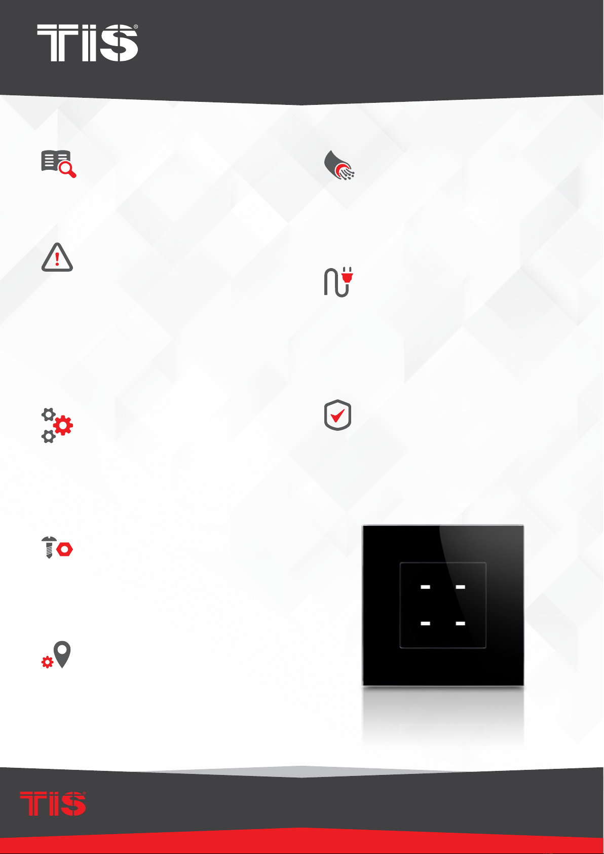
TIS TER-4G Safety guide

This product is a wall switch with touch buttons
designed for lights and motorized curtains
control. It offers customizable backlit color and
frame covers for an easy combination with
interior schemes.
PRODUCT INFORMATION
6 58921 79802 7
BARCODE (UPC-A)
PRODUCT SPECIFICATIONS
Touch Active area 1.5”
Touch type Capacitive
Input Temp sensor Resistive temp sensor
TIS Bus
Number of devices on 1 line Max. 64
Bus voltage 12-32 V DC
Current consumption <20 mA / 24 V DC
Protection Reverse polarity protection
ESD protection
Operation
Touch buttons 4 control buttons
Backlit LED indicators
TIS bus TIS protocol messages and commands
Upgrading By Rs485 upgrading kit
Dimensions Width × length × height 25mm × 45mm × 45mm
Housing
Materials Fireproof PC / Glass in front
Internal Parts color Black & gray
IP rating IP 50
TIS TERRE PANEL
4G Touch Switch
INSTALLATION MANUAL
Model: TER-4G
INSTALLATION MANUAL
MODEL : TER-4G
TIS TERRE PANEL
2
www.tiscontrol.com
TIS CONTROL LIMITED
Wanchai, Hong Kong
TIS CONTROL PTY LIMITED
SA , AUSTRALIA
Copyright © 2022 TIS, All Rights Reserved
TIS Logo is registered trademark of TIS CONTROL.
All of the specification are subject to change without notice.
Data Cable
Use screened stranded RS485 data cable
with four twisted pairs. Congure devices in
a “Daisy Chain.”
Do not cut or terminate live data cables.
Electrical Wires
The recommended wire size for light
channels is 1.5mm - 2.5mm for loads, if you
are using the Panel Addition 3R type. The
installer should consider the total current
consumption when selecting the wires.
Warranty
There is a two-year warranty provided
by law. The hologram warranty seal and
product serial number are available on
each device.
Read Instructions
We recommend that you read this
Instruction Manual before installation.
Safety instructions
Electrical equipment should only be
installed and tted by electrically skilled
persons.
Failure to follow the instructions may cause
damage to the device and other hazards.
These instructions are an integral part of
the product and must remain with the end
customer.
Programming
This device can be tested and programmed
manually. Advanced programming
requires knowledge of the TIS Device
Search software and instruction in the TIS
advanced training courses.
Simple Installation
You can use 2 screws to install this panel
on the wall; it ts European round and UK
square junction box sizes.
Mounting Location
Install in a dry, indoor area with a suitable
temperature and humidity range.
INSTALLATION MANUAL
MODEL : TER-4G
TIS TERRE PANEL
3
www.tiscontrol.com
TIS CONTROL LIMITED
Wanchai, Hong Kong
TIS CONTROL PTY LIMITED
SA , AUSTRALIA
Copyright © 2022 TIS, All Rights Reserved
TIS Logo is registered trademark of TIS CONTROL.
All of the specification are subject to change without notice.
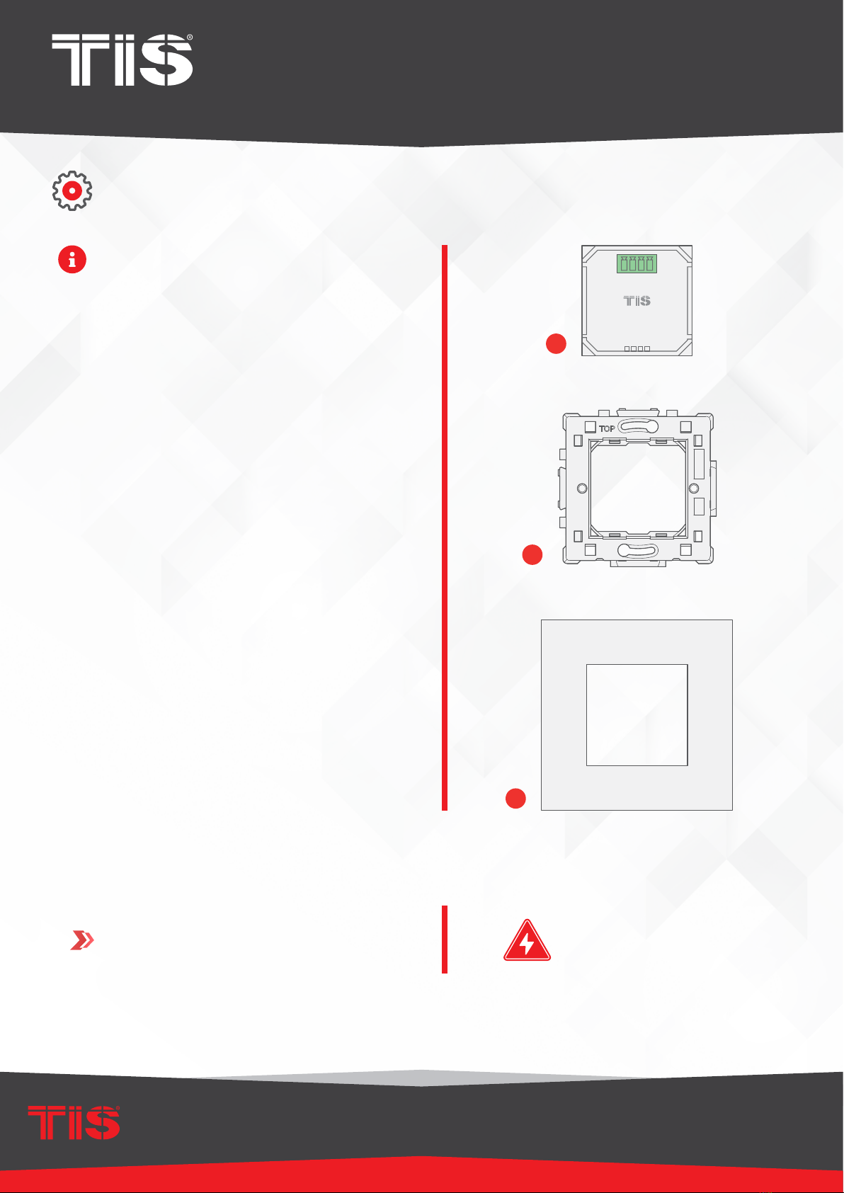
Turn off TIS power supply.
The TIS Terre wall switch consists of three
main components for installation; a base
module unit (g. 1), a wall base (g . 2),
and a top interface cover (g. 3).
The top cover comes in a variety of
materials, colors, and a customized
combination of 1-4 gangs.
1
INSTALLATION STEPS
1
2
3
WARNING! HIGH VOLTAGE

INSTALLATION MANUAL
MODEL : TER-4G
TIS TERRE PANEL
4
www.tiscontrol.com
TIS CONTROL LIMITED
Wanchai, Hong Kong
TIS CONTROL PTY LIMITED
SA , AUSTRALIA
Copyright © 2022 TIS, All Rights Reserved
TIS Logo is registered trademark of TIS CONTROL.
All of the specification are subject to change without notice.
INSTALLATION STEPS
Insert the Terre Module inside the Terre
Base by pushing it inside. Please note
the “TOP” label on the base in order to
insert the module correctly.
2
3Connect the TIS-BUS Cable to the
connector, and insert it into the Terre
module.
Cat5e

INSTALLATION MANUAL
MODEL : TER-4G
TIS TERRE PANEL
5
www.tiscontrol.com
TIS CONTROL LIMITED
Wanchai, Hong Kong
TIS CONTROL PTY LIMITED
SA , AUSTRALIA
Copyright © 2022 TIS, All Rights Reserved
TIS Logo is registered trademark of TIS CONTROL.
All of the specification are subject to change without notice.
Install the Terre base into the wall, and x
it with 2 screws.
INSTALLATION STEPS
5
4
6
Install the Terre cover on the Terre base.
Turn the power supply ON. The Terre
panel should turn on.

INSTALLATION MANUAL
MODEL : TER-4G
TIS TERRE PANEL
6
www.tiscontrol.com
TIS CONTROL LIMITED
Wanchai, Hong Kong
TIS CONTROL PTY LIMITED
SA , AUSTRALIA
Copyright © 2022 TIS, All Rights Reserved
TIS Logo is registered trademark of TIS CONTROL.
All of the specification are subject to change without notice.
INSTALLATION STEPS
The Terre series is modular, so you can
combine 2 to 4 different Terre panels,
switches, or plugs together vertically or
horizontally. To do so, follow these steps:
1Combine 2, 3, or 4 bases together
horizontally or vertically. Please note that
all “TOP” labels should always be in the
correct position.
▸
The following picture shows how to
install 2 bases horizontally.
▸
The following picture shoes how to
install 2 bases vertically.

INSTALLATION MANUAL
MODEL : TER-4G
TIS TERRE PANEL
7
www.tiscontrol.com
TIS CONTROL LIMITED
Wanchai, Hong Kong
TIS CONTROL PTY LIMITED
SA , AUSTRALIA
Copyright © 2022 TIS, All Rights Reserved
TIS Logo is registered trademark of TIS CONTROL.
All of the specification are subject to change without notice.
INSTALLATION STEPS
2
3
Insert the Terre panels, switches, or plugs
into the base.
Cover with the Terre 2-, 3-, or 4-gang
covers according to the combination.
INSTALLATION MANUAL
MODEL : TER-4G
TIS TERRE PANEL
8
www.tiscontrol.com
TIS CONTROL LIMITED
Wanchai, Hong Kong
TIS CONTROL PTY LIMITED
SA , AUSTRALIA
Copyright © 2022 TIS, All Rights Reserved
TIS Logo is registered trademark of TIS CONTROL.
All of the specification are subject to change without notice.
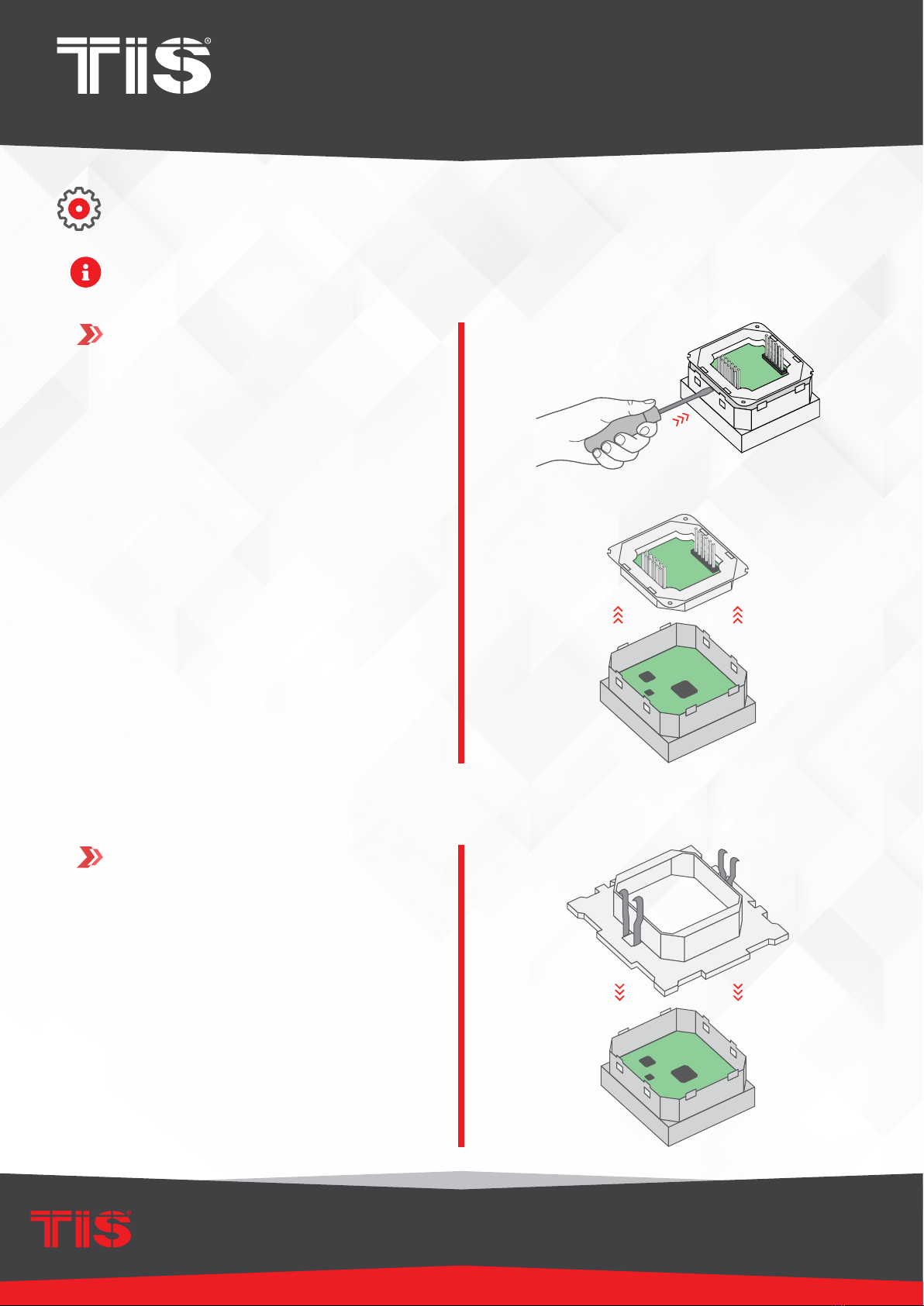
To use the Terre with Panel Addition, you should select Model TER-4G-A and follow these
steps:
1
2
Remove the back Terre part.
Insert the Terre panel into the Terre base.
INSTALLATION STEPS

INSTALLATION MANUAL
MODEL : TER-4G
TIS TERRE PANEL
9
www.tiscontrol.com
TIS CONTROL LIMITED
Wanchai, Hong Kong
TIS CONTROL PTY LIMITED
SA , AUSTRALIA
Copyright © 2022 TIS, All Rights Reserved
TIS Logo is registered trademark of TIS CONTROL.
All of the specification are subject to change without notice.
4
5
Connect any panel addition type that
supports the Terre panel.
Follow the connection diagram as per the
type of panel addition.
O-OFF
I-ON
MCB
GND(white-orange)&(white-brown)
D-(white-green)&(white-blue)
D+(blue-green)
+24V(brown-orange)
Cat5e connection
1.5 mm Electric Cable
1.5 mm Electric Cable
2.5 mm Electric Cable
PANEL ADDITION
3 Output Relay 5 Amp
Model : ADD-3R-5A
TIS BUS Input : 45-75mA/24V DC
Output Current : 3A220VAC
COM OUT3 OUT2 OUT1 COM
www.tissmarthome.com
D- +24V
GND D+
TER-4G-A
Connect To L
Connect To N
Cat5e
To the TIS BUS Network
INSTALLATION STEPS
3Connect the back part to the panel again.
INSTALLATION MANUAL
MODEL : TER-4G
TIS TERRE PANEL
10
www.tiscontrol.com
TIS CONTROL LIMITED
Wanchai, Hong Kong
TIS CONTROL PTY LIMITED
SA , AUSTRALIA
Copyright © 2022 TIS, All Rights Reserved
TIS Logo is registered trademark of TIS CONTROL.
All of the specification are subject to change without notice.
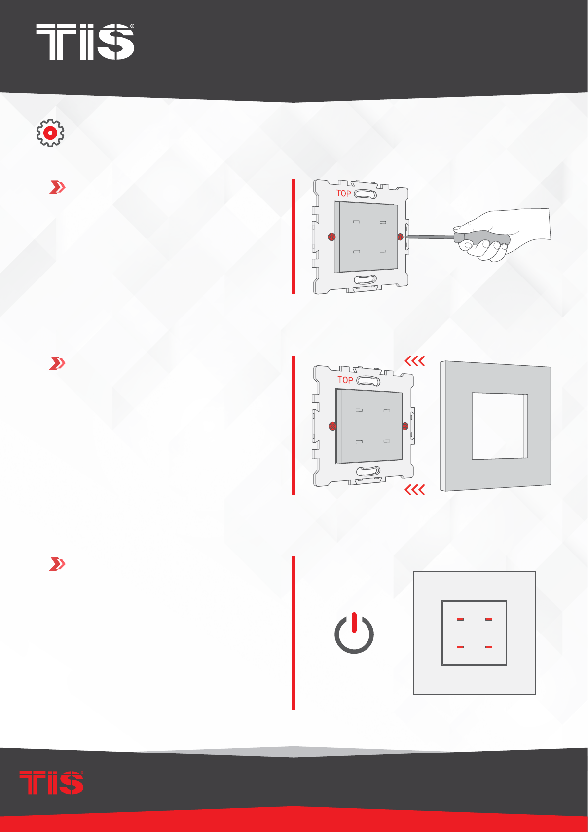
INSTALLATION STEPS
Install the Terre base into the wall, and x
it with 2 screws.
7
6
8
Install the Terre cover on the Terre base.
Turn the power supply ON. The Terre
panel should turn on.
INSTALLATION MANUAL
MODEL : TER-4G
TIS TERRE PANEL
11
www.tiscontrol.com
TIS CONTROL LIMITED
Wanchai, Hong Kong
TIS CONTROL PTY LIMITED
SA , AUSTRALIA
Copyright © 2022 TIS, All Rights Reserved
TIS Logo is registered trademark of TIS CONTROL.
All of the specification are subject to change without notice.
PAIRING (MANUAL PROGRAMMING)
RCU80-UT8-IN WARNING! HIGH VOLTAGE!
TIS-BUS
GND D- D+ 24+V
PRG
1 2 3 4 5 678
1 2 3 4 5 678
-+
8
7
GND
6
54
32
10-0V
DIGITAL INPUT
GND
1
6”
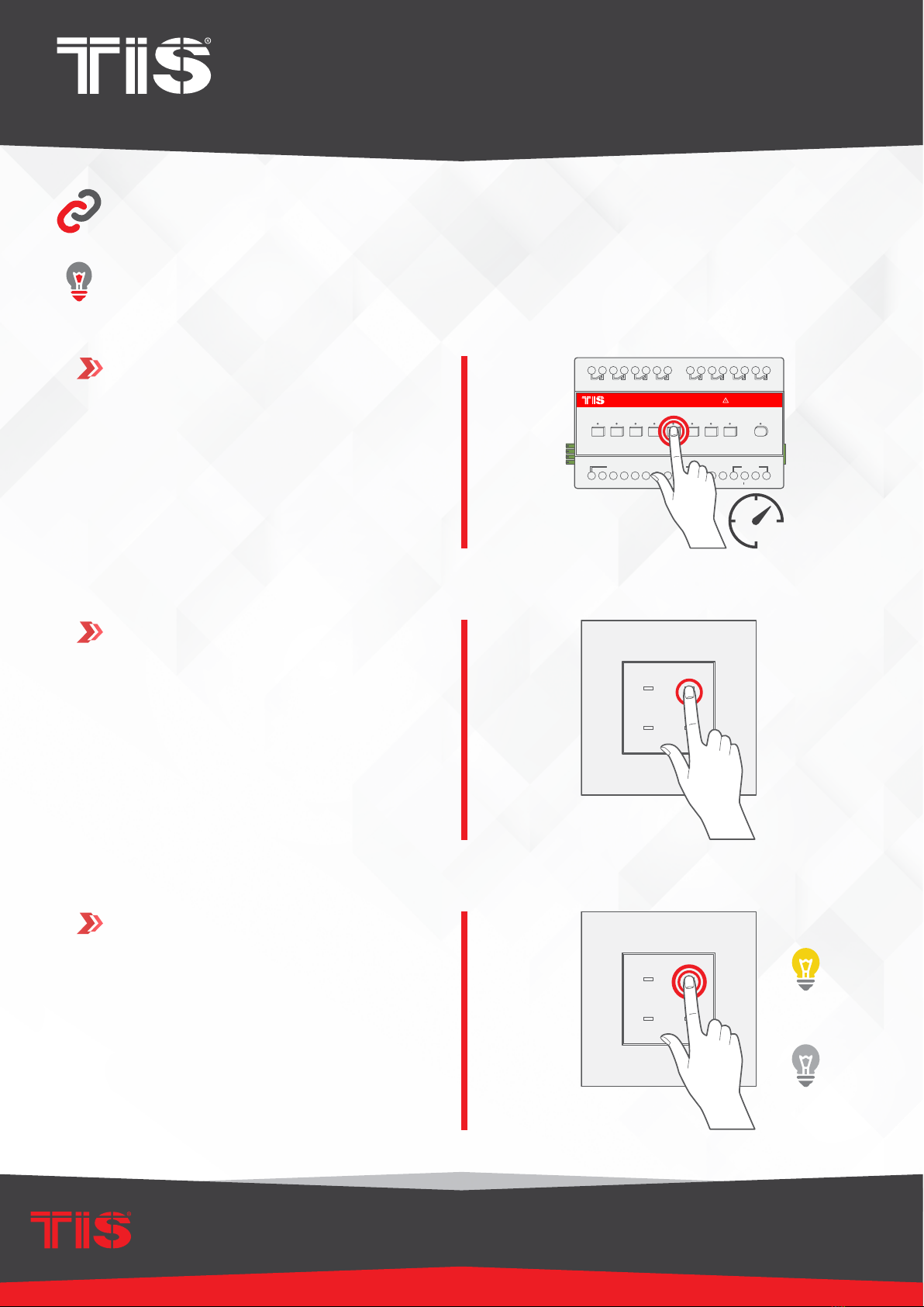
LIGHTS / SHUTTERS PROGRAMMING
You can pair the light channels with any wall panel. To do so, follow these steps:
1Press any button on any channel of a
relay or dimmer module for 6 seconds so
that the LED indicator light of that button
starts blinking.
Shortly press on any button on the wall
panel.
2
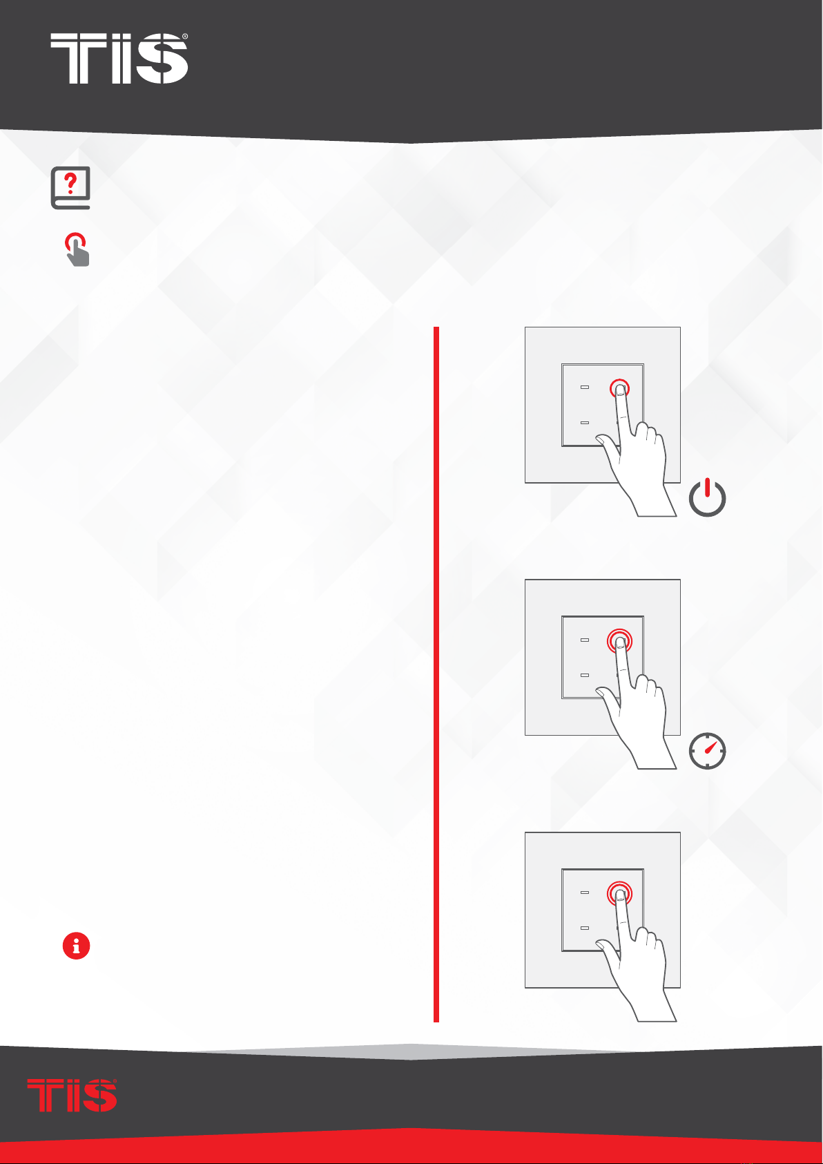
Test the button on the panel by short
pressing it for ON/OFF and long pressing
it to dim (if channel is dimmable).
3
INSTALLATION MANUAL
MODEL : TER-4G
TIS TERRE PANEL
12
www.tiscontrol.com
TIS CONTROL LIMITED
Wanchai, Hong Kong
TIS CONTROL PTY LIMITED
SA , AUSTRALIA
Copyright © 2022 TIS, All Rights Reserved
TIS Logo is registered trademark of TIS CONTROL.
All of the specification are subject to change without notice.
USER MANUAL
You can use the panel buttons 1-4; press on any button to get the settings that you
programmed.
▸
Short press for ON/OFF or to run a
scene.
▸
Double click to trigger a special
programmed scene.
All panel LEDs’ RGB can be programmed
to different colors in ON/OFF status.
▸
Long press to dim or ramp up the lights.
USING THE PANEL
×2
INSTALLATION MANUAL
MODEL : TER-4G
TIS TERRE PANEL
13
www.tiscontrol.com
TIS CONTROL LIMITED
Wanchai, Hong Kong
TIS CONTROL PTY LIMITED
SA , AUSTRALIA
Copyright © 2022 TIS, All Rights Reserved
TIS Logo is registered trademark of TIS CONTROL.
All of the specification are subject to change without notice.
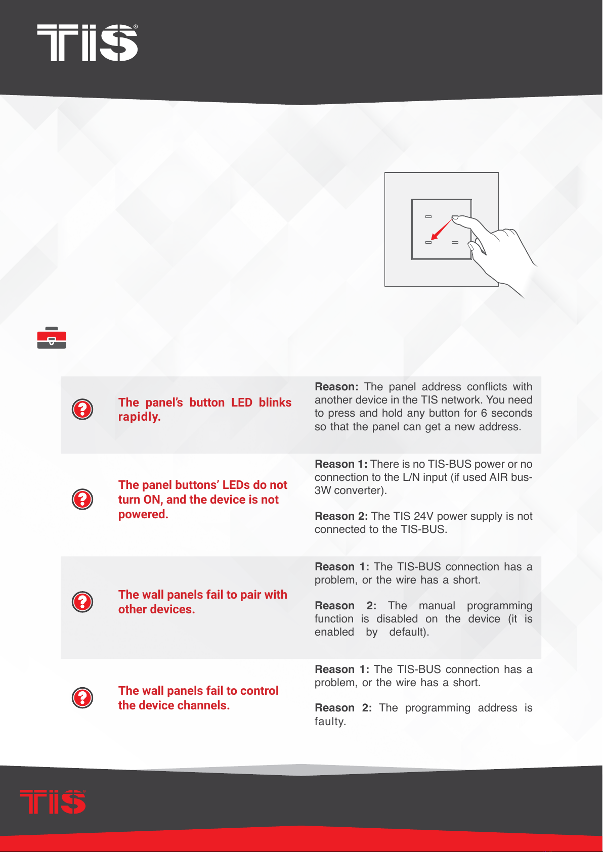
TROUBLESHOOTING
The panel’s button LED blinks
rapidly.
Reason: The panel address conicts with
another device in the TIS network. You need
to press and hold any button for 6 seconds
so that the panel can get a new address.
The panel buttons’ LEDs do not
turn ON, and the device is not
powered.
Reason 1: There is no TIS-BUS power or no
connection to the L/N input (if used AIR bus-
3W converter).
Reason 2: The TIS 24V power supply is not
connected to the TIS-BUS.
The wall panels fail to pair with
other devices.
Reason 1: The TIS-BUS connection has a
problem, or the wire has a short.
Reason 2: The manual programming
function is disabled on the device (it is
enabled by default).
The wall panels fail to control
the device channels.
Reason 1: The TIS-BUS connection has a
problem, or the wire has a short.
Reason 2: The programming address is
faulty.
Other manuals for TER-4G
1
Table of contents
Other TIS Switch manuals


Popular Switch manuals by other brands


D-Link
D-Link 5000 Series Cli reference guide

Linksys
Linksys EG005W - Instant Gigabit Workgroup Switch user guide

H3C
H3C S5130-28F-EI Configuration guide

Lightwave Communications
Lightwave Communications System Console Switch user manual

Jinan USR IOT Technology
Jinan USR IOT Technology USR-G781 user manual

ITT
ITT NEO-DYN 182P Installation and operation manual


