1. X-RAY RADIATION PRECAUTION
1) Excessive high voltage can produce potentially haz-
ardous X-RAY RADIATION to avoid such hazards, the
high voltage must not be above the specified limit. The
nominal value of the high voltage of this receiver is
24.4kv (27.5kv) at zero beam current (mininum
brighrness) under a 120V AC power source. The high
voltage must not, under any circumstance, exceed 27kv
(28.5kv). Each time a receiver requires servicing, the
high voltage should be checked following the HIGH
VOLTAGE CHECK procedure on page 4 of this manual.
It is recommend as parts of the servuce record. It is
important to use an accurate and reliable high voltage
meter.
2) This receiver is equipped with X-RADITION PROTEC-
TION circuit which prevents the receiver from producing
an excessively high voltage even of the B+ vlotage
increases abnormally. Each time the receiver is serviced,
X-RADIATION PROTECTION circuit must be checked to
determine that the circuit is properly functioning, following
the X-RADIATION PROTETION CIRCUIT CHECK pro-
cedure on page 4 of this manual.
3) The only source of X-RAY RADIATION in this TV receiv-
er is the picture tube. For continued X-RAY RADIATION
PROTECTION, the replacement tube must be exactly
the same type tube as specified in the parts list.
4) Some parts in the receiver have special safety-related
characteristics for X-RAY RADIATION PROTECTION.
for continued safety, parts replacement should be under-
taken only after referring to the PRODUCT SAFETY
NOTICE below.
2. SAFETY PRECAUTION
WARNING : Service should not be attempted by anyone
unfamiliar with the necessary precautions on this receiver.
The following are the necessary precaution to be observed
before servicing.
1) Since the chassis of this receiver has hazardous poten-
tial to ground whenever to receiver is plugged in (floating
chassis), an isolation transformer must be used during
service to avoid shock hazard.
2) Always discharge the picture tube anode to the CRT con-
ductive coating before handling the picture tube.
The picture tube is highly evacuated and if broken, glass
fragments will be violently expelled. Use shat-ter-proof
goggles and keep picture tube away from the body while
handling.
3) When replacing a chassis in the cabinet, always be cer-
tain that all the protective devices are put back in place,
such as; non-metallic control knobs, insulating covers,
shields, isolation resistor-capacitor network etc.
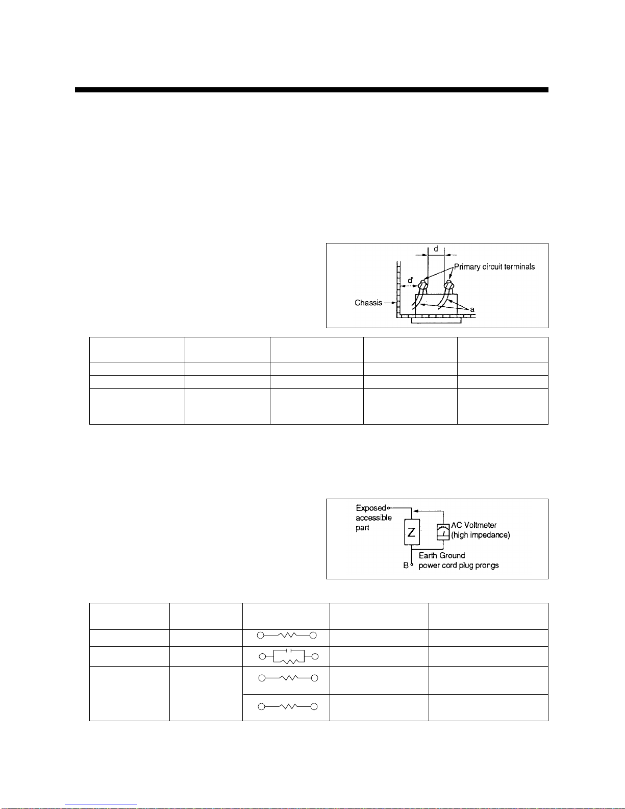
4) Before returning the set to the customer, always perform
an AC leakage curent check on the exposed metallic
parts of the cabinet, such as antennas, terminals, screw-
heads, metal overlays, control shafts etc. to be sure the
set is safe to operate without danger of electrical shock.
(Plug the AC line cord directly into a 120V AC outlet do
not use a line isolation transformer during this check).
Use an AC voltmeter having 5000 ohms per volt or more
sensitivity in the following manner.
Connect at 1500 ohm watt resistor, paralleled by a 0.15
mfd, AC type capacitor, between a known good earth
ground (water pipe, conduit, etc.) and the exposed metalic
parts, one at a time. Measure the AC voltage across the
combination of 1500 ohm resistor and o.15 mfd capacitor.
Reverse the AC plug at the AC output and repeat AC volt-
age measurements for each exposed metallic part. Voltage
messured much not exceed 0.3 volts RMS. this corre-
sponds to 0.2 milliamp AC. Any value exceeding this limit
constitutes a potential shock hazard and must be corrected
immediately.
3. PRODUCT SAFETY NOTICE
many electrical and mechanical parts in this chassis have
special safety-related characteristics. These characteristics
are often passed unnoticed by a visual inspection and the
protection afforded by them cannot necessarily be obtained
by using replacement components rated for higher voltage,
wattage, etc. Replacement parts which have these special
safety characteristics are identified in this manual and its
supplements; electrical components having such features
are identified by shading on the schematic diagram and the
parts list.
Before replacing ant of these componrnts, read the parts list
in this manual carefully. The use of substitute replacement
parts which do not have the same safety characteristics as
specified in the parts list may create X-ray radiation or other
hazards.
4. SERVICE NOTES
1) Which replacing parts or circuit boards, clamp the lead
wires to terminals before soldering.
2) When replacing a high wattage resistor (metal oxide film
resistor) in the circuit board, keep the resistor min 1/2 inch
away from circuit board.
3) Keep wires away from high voltage or high temperature
components.
■■IMPORTANT SERVICE NOTES
3


D User manual")