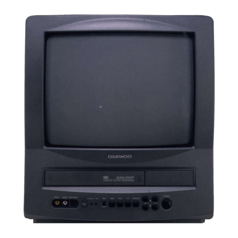
Daewoo DVQ-13H1FCN User manual

✔ Caution:In this Service Manual, some parts can be changed for improving, their performance without notice in the parts list. So, if you need the
latest parts information, please refer to PPL(Parts Price List) in Service information Center(http://svc.dwe.co.kr)

1
TABLE OF CONTENTS
SAFETY INSTRUCTION .................................................................................................... 2
SPECIFICATION ............................................................................................................ 5
CIRCUIT BLOCK DIAGRAM ............................................................................................ 6
ALIGNMENT INSTRUCTIONS............................................................................................ 8
SERVICE MODE ADJUSTMENTS......................................................................................................................8
ASSEMBLY ADJUSTMENTS..............................................................................................................................10
VCR DECK ADJUSTMENTS.............................................................................................................................12
SCHEMATIC DIAGRAM.................................................................................................. 13
EXPLODED VIEW .......................................................................................................... 14
PRINTED CIRCUIT BOARD............................................................................................... 18
SERVICE PARTS LIST ....................................................................................................... 19
APPENDIX ( Appendix is provided only by internet [http://svc.dwe.co.kr] )
IC DESCRIPTION ........................................................................................................... 1
TROUBLESHOOTING GUIDE............................................................................................ 10

2
SAFETY INSTRUCTION
CAUTION
: DO NOT ATTEMPT TO MODIFY THIS PRODUCT IN ANY WAY.
NEVER PERFORM CUSTOMIZED INSTALLATIONS WITHOUT MANUFAC-
TURER°ØS APPROVAL. UNAUTHORIZED MODIFICATIONS WILL NOT ONLY
VOID THE WARRANTY, BUT MAY LEAD TO YOUR BEING LIABLE FOR ANT
RESULTING PROPERTY DAMAGE OR USER INJURY.
SERVICE WORK SHOULD BE PERFORMED ONLY AFTER YOU ARE THOR-
OUGHLY FAMILIAR WITH ALL OF THE FOLLOWING SAFETY CHECKS AND
SERVICING GUIDELINES. TO DO OTHERWISE, INCREASES THE RISK OF
POTENTIAL HAZARDS AND INJURY TO THE USER.
WHILE SERVICING, USE AN ISOLATION TRANSFORMER FOR PROTECTION
FROM A.C. LINE SHOCK.
SAFETY CHECKS
AFTER THE ORIGINAL SERVICE PROBLEM HAS BEEN CORRECTED, A CHECK
SHOULD BE MADE OF THE FOLLOWING:
SUBJECT:FIRE & SHOCK HAZARD
1. BE SURE THAT ALL COMPONENTS ARE POSITIONED IN SUCH A WAY AS
TO AVOID POSSIBILITY OF ADJACENT COMPONENT SHORTS. THIS IS
ESPECIALLY IMPORTANT ON THOSE MODULES WHICH ARE TRANS-
PORTED TO AND FROM THE REPAIR SHOP.
2. NEVER RELEASE A REPAIR UNLESS ALL PROTECTIVE DEVICES SUCH AS
INSULATORS, BARRIERS, COVERS, SHIELDS, STRAIN RELIEFS, POWER
SUPPLY CORDS, AND OTHER HARDWARE HAVE BEEN REINSTALLED PER
ORIGINAL DESIGN. BE SURE, THAT THE SAFETY PURPOSE OF THE
POLARIZED LINE PLUG HAS NOT BEEN DEFEATED.
3. SOLDERING MUST BE INSPECTED TO DISCOVER POSSIBLE COLD SOL-
DER JOINTS, SOLDER SPLASHES OF SHARP SOLDER POINTS. BE CER-
TAIN TO REMOVE ALL LOOSE FOREIGN PARTICLES.
4. CHECK FOR PHYSICAL EVIDENCE OF DAMAGE OR DETERIORATION TO
PARTS AND COMPONENTS, FOR FRAYED LEADS, DAMAGED INSULATION
(INCLUDING A.C. CORD), AND REPLACE IF NECESSARY. FOLLOW ORIGI-
NAL LAYOUT, LEAD LENGTH AND DRESS.
5. NO LEAD OR COMPONENT SHOULD TOUCH A RECEIVING TUBE OR A
RESISTOR RATED AT 1 WATT OR MORE. LEAD TENSION AROUND PRO-
TRUDING METAL SURFACES MUST BE AVOIDED.
6. ALL CRITICAL COMPONENTS SUCH AS FUSES, FLAMEPROOF RESISTOR,
CAPACITORS, ETC. MUST BE REPLACED WITH EXACT FACTORY TYPES.
DO NOT USE REPLACEMENT COMPONENTS OTHER THAN THOSE SPECI-
FIED OR MAKE UNRECOMMENDED CIRCUIT MODIFICATIONS.
7. AFTER RE-ASSEMBLY OF THE STE ALWAYS PERFORM AN A.C. LEAKAGE
TEST ON ALL EXPOSED METALLIC PARTS OF THE CABINET. (THE CHAN-
NEL SELECTOR KNOB, ANTENNA TERMINALS, HANDLE AND SCREWS) TO
BE SURE THE SET IS SAFE TO OPERATE WITHOUT DANGER OF ELECTRI-
CAL SHOCK. DO NOT USE A LINE ISOLATION TRANSFORMER DURING
THIS TEST USE AN A.C. VOLTMETER, HAVING 5000 OHMS PER VOLT OR
MORE SENSITIVITY, IN THE FOLLOWING MANNER : CONNECT A 1500 OHM
10 WATT RESISTOR, PARALLELED BY A .15 MFD. 150V A.C. TYPE CAPACI-
TOR BETWEEN A KNOWN GOOD EARTH GROUND (WATER POPE, CON-
DUIT, ETC.) AND THE EXPOSED METALLIC PARTS, ONE AT A TIME.
MEASURE THE A.C. VOLTAGE ACROSS THE COMBINATION OF 1500 OHM
RESISTOR AND .15 MFD CAPACITOR. REVERSE THE A.C. PLUG AND
REPEAT A.C. VOLTAGE MEASUREMENTS FOR EACH EXPOSED METALLIC
PART. VOLTAGE MEASURED MUST NOT EXCEED .75 VOLTS R.M.S THIS
CORRESPONDS TO 0.5 MILLIAMP A.C. NAY VALUE EXCEEDING THIS LIMIT
CONSTITUTES A POTENTIAL SHOCK HAZARD AND MUST BE CORRECTED
IMMEDIATELY.
SUBJECT : GRAPHIC SYMBOLS
THE LIGHTNING FLASH WITH ARROWHEAD SYMBOL,
WITHIN AN EQUILATERAL TRIANGLE, IS INTENDED
TO ALERT THE SERVICE PERSONNEL TO THE PRES-
ENCE OF UNINSULATED “DANGEROUS VOLTAGE”
THAT MAY BE OF SUFFICIENT MAGNITUDE TO CON-
STITUTE A RISK OF ELECTRIC SHOCK.
THE EXCLAMATION POINT WITHIN AN EQUILATERAL
TRIANGLE IS INTENDED TO ALERT THE SERVICE
PERSONNEL TO THE PRESENCE OF IMPORTANT
SAFETY INFORMATION ON SERVICE LITERATURE.
SUBJECT : X-RADIATION
1. BE SURE PROCEDURES AND INSTRUCTIONS TO ALL SERVICE PERSON-
NEL COVER THE SUBJECT OF X-RADIATION. THE ONLY POTENTIAL
SOURCE OF X-RAYS IN CURRENT T.V. RECEIVERS IS THE PICTURE TUBE.
HOWEVER, THIS TUBE DOES NOT EMIT X-RAYS WHEN THE HIGH VOLT-
AGE IS AT THE FACTORY SPECIFIED LEVEL. THE PROPER VALUE IS
GIVEN IN THE APPLICABLE SCHEMATIC. OPERATION AT HIGHER VOLT-
AGES MAY CAUSE A FAILURE OF THE PICTURE TUBE OR HIGH VOLTAGE
SUPPLY AND, UNDER CERTAIN CIRCUMSTANCES, AMY PRODUCE RADIA-
TION IN EXCESS OF DESIRABLE LEVELS.
2. ONLY FACTORY SPECIFIED C.R.T ANODE CONNECTORS MUST BE USED.
DEGAUSSING SHIELDS ALSO SERVE AS X-RAY SHIELD IN COLOR SETS.
ALWAYS RE-INSTALL THEM.
3. IT IS ESSENTIAL THAT SERVICE PERSONNEL HAVE AVAILABLE AN ACCU-
RATE AND RELIABLE HIGH VOLTAGE METER. THE CALIBRATION OF THE
METER SHOULD BE CHECKED PERIODICALLY AGAINST A REFERENCE
STANDARD. SUCH AS THE ONE AVAILABLE AT YOUR DISTRIBUTOR.
4. WHEN THE HIGH VOLTAGE CIRCUITRY IS OPERATING PROPERLY THERE
IS NO POSSIBILITY OF AN X-RADIATION PROBLEM. EVERY TIME A COLOR
CHASSIS IS SERVICED, THE BRIGHTNESS SHOULD BE RUN UP AND
DOWN WHILE MONITORING THE HIGH VOLTAGE WITH A METER TO BE
CERTAIN THAT THE HIGH VOLTAGE DOES NOT EXCEED THE SPECIFIED
VALUE AND THAT IT IS REGULATING CORRECTLY. WE SUGGEST THAT
YOU AND YOUR SERVICE ORGANIZATION REVIEW TEST PROCEDURES
SO THAT VOLTAGE REGULATION IS ALWAYS CHECKED AS A STANDARD
SERVICING PROCEDURE, AND THAT THE HIGH VOLTAGE READING BE
RECORDED ON EACH CUSTOMER°ØS INVOICE.
5. WHEN TROUBLESHOOTING AND MAKING TEST MEASUREMENTS IN A
PRODUCT WITH A PROBLEM OF EXCESSIVE HIGH VOLTAGE, AVOID
BEING UNNECESSARILY CLOSE TO THE PICTURE TUBE AND THE HIGH
VOLTAGE SUPPLY. DO NOT OPERATE THE PRODUCT LONGER THAN IS
NECESSARY TO LOCATE THE CAUSE OF EXCESSIVE VOLTAGE.
6. REFER TO HV, B+ AND SHUTDOWN ADJUSTMENT PROCEDURES
DESCRIBED IN THE APPROPRIATE SCHEMATIC AND DIAGRAMS (WHERE
USED).
SUBJECT : IMPLOSION
1. ALL DIRECT VIEWED PICTURE TUBES ARE EQUIPPED WITH AN INTEGRA
IMPLOSION PROTECTION SYSTEM. BUT CARE SHOULD BE TAKEN TO
AVOID DAMAGE DURING INSTALLATION. AVOID SCRATCHING THE
TUBE. OF SCRATCHED REPLACE IT.
2. USE ONLY RECOMMENDED FACTORY REPLACEMENT TUBES.
SUBJECT : TIPS ON PROPER INSTALLATION
1. NEVER INSTALL ANY PRODUCT IN A CLOSED-IN RECESS, CUBBYHOLE OR
CLOSELY FITTING SHELF SPACE, OVER OR CLOSE TO HEAT DUCT, OR IN
THE PATH OF HEATED AIR FLOW.
2. AVOID CONDITIONS OF HIGH HUMIDITY SUCH AS: OUTDOOR PATIO
INSTALLATIONS WHERE DEW IS A FACTOR, NEAR STEAM RADIATORS
WHERE STEAM LEAKAGE IS A FACTOR, ETC.
3. AVOID PLACEMENT WHERE DRAPERIES MAY OBSTRUCT REAR VENTING.
THE CUSTOMER SHOULD ALSO AVOID THE USE OF DECORATIVE
SCARVES OR OTHER COVERINGS WHICH MIGHT OBSTRUCT VENTILA-
TION.
4. WALL AND SHELF MOUNTED INSTALLATIONS USING A COMMERCIAL
MOUNTING KIT, MUST FOLLOW THE FACTORY APPROVED MOUNTING
INSTRUCTIONS.A PRODUCTMOUNTED TOA SHELF ORPLATFORM MUST
RETAIN ITS ORIGINAL FEET (OR THE EQUIVALENT THICKNESS IN SPAC-
ERS)TO PROVIDE ADEQUATE AIR FLOW ACROSS THE BOTTOM, BOLTS
OR SCREWS USED FOR FASTENERS MUST NOT TOUCH ANY PARTS OR
WIRING. PERFORM LEAKAGE TEST ON CUSTOMIZED INSTALLATIONS.
5. CAUTION CUSTOMERS AGAINST THE MOUNTING OF A PRODUCT ON
SLOPING SHELF OR A TILTED POSITION, UNLESS THE PRODUCT IS
PROPERLY SECURED.
6. A PRODUCT ON A ROLL-ABOUT CART SHOULD BE STABLE ON ITS MOUNT-
ING TO THE CART. CAUTION THE CUSTOMER ON THE HAZARDS OF TRY-
ING TO ROLL A CART WITH SMALL CASTERS ACROSS THRESHOLDS OR
DEEP PILE CARPETS.
7. CAUTION CUSTOMERS AGAINST THE USE OF A CART OR STAND WHICH
HAS NOT BEEN LISTED BY UNDERWRITERS LABORATORIES. INC. FOR
USE WITH THEIR SPECIFIC MODEL OF TELEVISION RECEIVER OR
GENERICALLY APPROVED FOR USE WITH T.V.S OF THE SAME OR
LARGER SCREEN SIZE.
8. CAUTION CUSTOMERS AGAINST THE USE OF EXTENSION CORDS,
EXPLAIN THAT A FOREST OF EXTENSIONS SPROUTING FROM A SINGLE
OUTLET CAN LEAD TO DISASTROUS CONSEQUENCES TO HOME AND
FAMILY.
10WATT
GOOD EARTH GROUND
SUCH AS THE WATER
PIPE, CONDUIT, ETC. 1500 OHM
A.C. VOLTMETER
PLACE THIS PROBE
ON EACH EXPOSED
METAL PART
0.15uF
3
SAFETY INSTRUCTION
CAUTION : Do not attempt to modify this product in any way. Unau-
thorized modifications will not only void the warranty, but may lead to
your being liable for any resulting property damage or user injury.
Service work should be performed only after you are thoroughly
familiar with all of the following safety checks and servicing guide-
lines. To do otherwise, increases the risk of potential hazards and
injury to the user.
SAFETY CHECKS
Afterthe original serviceproblem hasbeen corrected,a check should
be made of the following:
SUBJECT : FIRE & SHOCK HAZARD
1. Be sure that all components are positioned in such a way as to
avoid possibility of adjacent component shorts. This is especially
important on those chassis which are transported to and from the
repairshop.
2.Never release arepair unlessall protective devicessuch asinsula-
tors, barriers, covers, shields, strain reliefs, and other hardware
have been reinstalled per original design.
3.Soldering mustbe inspected todiscover possiblecold solderjoints,
frayed leads, damaged insulation (including A.C. cord), solder
splashes or sharp solder points. Be certain to remove all loose for-
eign particals.
4. Check for physical evidence of damage or deterioration to parts
and components, and replace if necessary follow original layout,
lead length and dress.
5.Noleads orcomponentsshould touchareceiving tubeora resistor
rated at 1 watt or more. Lead tension around protruding metal sur-
faces must be avoided.
6. All critical components such as fuses, flameproof resistors, capaci-
tors, etc. must be replaced with exact factory types. Do not use
replacement components other than those specified or make
unrecommendedcircuit modifications.
7. After re-assembly of the set always perform an A.C. leakage test
on all exposed metallic parts of the cabinet, (the channel selector
knob, antenna terminals, handle and screws) to be sure the set is
safe to operate without danger of electrical shock. Do not use a
line isolation transformer during this test. Use an A.C. voltmeter,
having 5000 ohms per volt or more sensitivity, in the following
manner : connect a 1500 ohm 10 watt resistor, paralleled by a 15
mfd. 150V A.C. type capacitor between a known good earth
ground (9water pipe, conduit, etc.) and the exposed metallic parts,
one at a time. Measure the A.C. voltage across the combination of
1500 ohm resistor and 0.15 MFD capacitor. Reverse the A.C. plug
and repeat A.C. voltage measurements for each exposed metallic
part. Voltage measured must not exceed 0.75 volts R.M.S. This
corresponds to 0.5 milliamp A.C. Any value exceeding this limit
constitutes a potential shock hazard and must be corrected imme-
diately.
GRAPHIC SYMBOLS :
The lightning flash with arrowhead symbol,
within an equilateral triangle, is intended to alert
theservice personnelto the presenceof uninsu-
lated “dangerous voltage” that may be of suffi-
cienty magnitude to constitute a risk of electric
shock.
The exclamation point within an equilateral tri-
angle is intended to alert the service personnel
to the presence of important safety information
inserviceliterature.
Fuse symbol is printed on pcb adjacent to the
fuse, with “RISK OF FIRE REPLACE FUSE AS
MARKED”. The symbol is explained in the ser-
vice manual with the following wording or equiv-
alent.
“CAUTION :
FOR CONTINUED PROTECTION AGAINST FIRE
HAZARD, REPLACE ONLY WITH SAME TYPE (6.3A, 250V)” and
“
ATTENTION
: AFIN D’ASSU UNE PROTECTION PERMANENTE
CONTRE LES RISQUES D’INCENDIE, REMPLACER UNIQUE-
MENT PAR UN FUSIBLE DE MEME TYPE ET DE ”6.3A, 250V”.
SUBJECT : X-RADIATION
1. Be sure procedures and instructions to all service personnel cover
the subject of X-rays in current T.V. receivers is the picture tube.
However, this tube does not emit X-rays when the high voltage is
atthe factoryspecifiedlevel. Theproper valueisgiven inthe appli-
cable schematic. Operation at higher voltages may cause a failure
of the picture tube or high voltage supply and, under certain cir-
cumstances, may produce radiation in excess of desirable levels.
2. Only factory specified C.R.T. anode connectors must be used.
Degaussing shields also serve as X-ray shield in color sets.
Alwaysre-install them.
3. It is essential that the serviceman has available an accurate and
reliable high voltage meter. The calibration of the meter should be
checked perio - dically against a reference standard. Such as the
one available at your distributor.
4. When the high voltage circuitry is operating properly there is no
possibility of an X-radiation problem. Every time a color chassis is
serviced, the brightness should be run up and down while monitor-
ingthe highvoltage witha meterto becertain thatthe highvoltage
does not exceed the specified value and that it is regulating cor-
rectly. We suggest that you and your service organization review
test procedures so that voltage regulation is always checked as a
standardservicing procedure.Andthat thehighvoltage readingbe
recorded on each customer’sinvoice.
5. When troubleshooting and making test measurements in a
receiver with a problem of excessive high voltage, avoid being
unnecessarilyclosetothepicturetubeandthehighvoltagecompartment.
Do not operate the chassis longer than is necessary to locate the
cause of excessive voltage.
6. Refer to HV, B+and Shutdown adjustment procedures described in
the appropriate schematic and diagrams(where used).
10WATT
Good earth ground,
such as the water
pipe, conduit, etc. 1500 OHM
A.C. VOLTMETER
Place this probe
on each exposed
metal part.
0.15 uF

4
SAFETY INSTRUCTION
SUBJECT : IMPLOSION
1. All direct viewed picture tubes are equipped with an integral implo-
sion protection system, but care should be taken to avoid damage
during installation. Avoid scratching the tube. If scratched, replace
it.
2. Use only recommended factory replacement tubes.
SUBJECT : TIPS ON PROPER INSTALLATION
1. Never install any receiver in closed-in recess, cubbyhole or closely
fitting shelf space over, or close to heat duct, or in the path of
heatedair flow.
2. Avoid conditions of high humidity such as : Outdoor patio installa-
tions where dew is a factor. Near steam radiators where steam
leakage is a factor, etc.
3. Avoid placement where draperies may obstruct rear venting. The
customer should also avoid the use of decorative scarves or other
coverings which might obstruct ventilation.
4. Wall and shelf mounted installations using a commercial mounting
kit, must follow the factory approved mounting instructions. A
receiver mounted to a shelf or platform must retain its original
feet(or the equivalent thickness in spacers) to provide adequate
are flow across the bottom, bolts or screws used for fasteners
must not touch and parts or wiring. Perform leakage test on cus-
tomized installations.
5. Caution customers against the mounting of a receiver on sloping
shelf or a tilted position, unless the receiver is properly secured.
6. A receiver on a roll-about cart should be stable on its mounting to
thecart. Cautionthecustomer onthe hazardsoftrying toroll acart
with small casters across thresholds or deep pile carpets.
7.Caution customers againstthe useof a cartor standwhich has not
been listed by underwriters laboratories, inc. For use with their
specific model of television receiver or generically approved for
usewith T.V.’s of the same or larger screen size.

5
SPECIFICATION
ITEMS MODEL DVQ-13/19H1FCN, DVQ-13/19H2FCN REMARK
TV
SECTION STANDARD NTSC-M
TUNING SYSTEM Frequency Synthesizer(FS) Tuning System
TUNING RANGE VHF : 2 - 13(12)
UHF : 14 -69(56)
CATV : 1-125(125)
ANTENNA INPUT IMPEDENCE 75ohm Unbalanced
AUXILIARY INPUT TERMINAL Front : Video, Audio
VIDEO
SECTION FORMAT VHS NTSC Standard
VCR SYSTEM Rotary 2-Head Helical Scanning
MonauralSystem
AUDIO RECORDING SYSTEM Monaural
TAPE SPEED SP:33.35mm/sec; EP:11.12mm/sec
LP:16.67mm/sec PLAY ONLY
INPUT Video :1Vp-p,75 Ohm
Audio :3.8dBm, over 100K Ohm
TIMER PROGRAMING 6 Event/1 Month
GENERAL POWER INPUT AC 120V 60Hz
POWER CONSUMPTION 13=60W
SOUND OUTPUT 1.3W
SPEAKER 3W 8 OHM
OPRATING TEMPERATRE 5
°
C to 40
°C
REMOTE CONTROL R-39A02
SPECIAL FUNTION 3-Language OSD
With CAPTION
Parental Control
K-50MECHA
One Touch Record
Repeat Play
Energy Star Power (Stand-By:2W Under)

6
CIRCUIT BLOCK DIAGRAM

7
CIRCUIT BLOCK DIAGRAM

ALIGNMENT INSTRUCTIONS
1. SERVICE MODE ADJUSTMENTS
Follow the steps below whenever service adjustment is required. See Table-A.
and Table-B to determine if service adjustments are required.
1)How to enter the service mode using the user remote control.
w
Turn the set on.
w
Direct the remote control to the reception window of your TV/VCR
w
Push buttons of remote control in sequence as follows.
1
Z
MUTE
Z
RECALL
Z
MUTE
w
Then, the screen will appear as follows.
w
Using the channel up ( s ) or down ( t ) buttons, select the item you wish to adjust..
The curser (
U
) move you wish to adjust item.
w
Using the volume up (
U
) or down(
) buttons to enter in the sevice mode you wish to adjust.
w
You adjust the values of service mode, automatically save to EEPROM
Table-A : Adjust the values of service mode when a part is replaced
PART
REPLACE ADJUSTMENT NOTE
NECESSARY UNNECESSARY
ICS01
(TIMER/SYSCON) OData is stored in IS03(EEPROM)
I501
(TV CHROMA) O
IS03
(EEPROM) OInitial setting values are written from ICS01
Adjusting Items
S5:IFC, S6:GEO, S8:W/B, S9:DP,S11:PG Adjust
CRT OAdjusting Items
S2:SCRN, S6:GEO, S8:W/B, S9:DP
VCR DECK
(DRN-7203) OAdjusting Items related to VCR DECK only.
S10:ATK OFF, S11:PG Adjust
ICY01
(VCR Y/C) O
U
S2
S5
S6
S8
S9
S10
S11
S12
FIELE SVC
SCRN
IFC
GEO
W/B
DP
ATK OFF
PG Adjust
FACT
8

ALIGNMENT INSTRUCTIONS
Table-B
*1 indicates the items with differnt settings each of sets.
*2 CROSS BW: Internal pattern of Device(I501:DCT814B)
Whenever you select the "CROSS BW" using volume up(
U
) or down( ) button,
the screen is changing like this;
VOL UP (
U
)
NORMAL
Z
BLACK
Z
WHITE100
Z
WHITE60
Z
CROSS
VOL DOWN ( )
MODE ADJUSTMENT ITEMS DATA REMARK
INITIAL RANGE
S2 Screen Adjustment - -
S5:
IF
CONTROL
AGC Auto - - Automatical adjustment
AGC Vol 3.75V -Select AGC reference voltage (3.75V)
AGC * 1 0-63 Align RF AGC threshold
VIDEO LEV 007 0-7 Must be set to 7
FM LEV 005 0-31 Must be set to 5
HFREQ 012 0-63 NOT USED
CROSS BW * 2 - - NOT USED
S6:
GEOMETRY H CENTER (Horizontal center) * 1 0-31 Using internal cross pattern
(CROSS BW * 2)
V SIZE (Vetical Size) * 1 0-127
V CENTER (Vertical Center) * 1 0-63
V SC (Vertical S-Correction) 00-31 Must be set to 0
V LIN (Vertical Linearity) 20 0-31 Must be set to 20
NO SD POWER OFF NO Automatically turn off in 15min for no received signal (YES)
CROSS BW * 2 - -
HBLKR 10-6 Must be set to 1
HBLKL 60-6 Must be set to 6
S8:
WHITE
BALANCE
RD(Red Drive) * 1 0-127 Using internal 100% WHITE pattern
(CROSS BW * 2)
GD(Green Drive) 10 0-15
BD(Blue Drive) * 1 0-127
RB(RedBias) * 1 0-255 Using internal 60% WHITE pattern
(CROSS BW * 2)
GB(Green Bias) * 1 0-255
BB(Blue Bias) * 1 0-255
CROSSBW * 2 - -
S9
D.P Brightness * 1 0-63
sharpness 00-63
Color 35 0-63
Tint 22 0-63
S10 ATK(Auto Tracking) OFF - - For VCR DECK Adjustment
S11 PG Adjustment - - Automatically P.G Adjustment
S12 FACT - - Factory Initialization
ZZZZ
9

ALIGNMENT INSTRUCTIONS
2. ASSEMBLY ADJUSTMENTS
1) SCREEN ADJUSTMENT(S2)
w
Enter the service mode and select service adjustment S2
w
You can see the horizontal straight line on the screen
w
Adjust the Screen Control volume(located on FBT) so that the horizontal straight line on screen may be disappear.
w
Press the MENU button to exit the screen adjustment mode.
2) FOCUS ADJUSTMENT(S2)
w
Turn in a local station and the Focus Control volume(located on FBT) for best picture details at light condition.
3) RF-AGC ADJUSTMENT(S5)
w
Receive a good local channel.
w
Enter the service mode and select service adjustment S5
w
You can see the OSD as shown in below.
w
Select AGC item, press volume up (
U
) or down( ) buttons until noise or beet in picture disappears.
4) GEOMETRIC ADJUSTMENT(S6)
w
Enter the service mode and select service adjustment S6
w
You can see the OSD as shown in below.
w
Use the CH up ( s ) or down ( t ) buttons to select "CROSS BW" item.
w
Use the VOL up (
U
) button to select internal cross pattern.
AGC Auto
IF CONTROL
AGC Vol 3.75V
AGC 000
VIDEO LEV 005FM LEV 007
HFREQ 012
CROSS BW
H CENTER
GEOMETRY
V SIZE 060
V CENTER 040
V SC 020V LIN 000
NO SD POWER OFF NO
CROSS BW
020
HBLKR 1 HBLKL 6
H CENTER
GEOMETRY
V SIZE 060
V CENTER 040
V SC 020
V LIN 000
NO SD POWER OFF NO
CROSS BW
020
HBLKR 1 HBLKL 6
- Figure1 -
10

ALIGNMENT INSTRUCTIONS
4-1.HORIZONTAL CENTER Adjustment
w
Select H CENTER item, adjust H CENTER data value to obtain proper horizontal centering of the internal cross
pattern at the left and right of the screen.
4-2.VERTICAL CENTER Adjustment
w
Select V CENTER item, adjust V CENTER data value to center the raster properly on the screen.
4-3.VERTICAL SIZE Adjustment
w
Select V SIZE item, adjust V SIZE data value to proper vertical size as figure 1.
5) WHITE BALANCE ADJUSTMENT(S8)
w
Enter the service mode and select service adjustment S8.
w
You can see the OSD as shown in below.
NOTE:
The color coordinator to x:285, y:290.
w
Use the CH up( s ) or down ( t ) buttons to select "CROSS BW" item.
w
Use the VOL up (
U
) button to select internal WHITE60 pattern.
w
Use the CH s tbuttons to select RB/GB/BB item, adjust data until a good white.
w
Use the CH stbuttons to select "CROSS BW" item.
w
Use the VOL
U
button to select internal WHITE100 pattern.
w
Use the CH stbuttons to select RD/BD item, adjust data until a good white.
6) D.P(DIGITAL PRESET) ADJUSTMENT(S9)
SUBBRIGHTNESS Adjustment
w
Receive a good local channel.
w
Enter the service mode and select service adjustment S9
w
You can see the OSD as shown in below.
NOTE :
SUBBRIGHTNESS = RETMA PATTERN : 8%
w
Select Brightness item, adjust Brightness data value to obtain normal brightness level.
Sharpness
w
Fixed value = 000
Color
w
Fixed value = 035
Tint
w
Fixed value = 022
RD
GD 010
BD 063
GB 127BB
127
CROSS BW
063
RB 127
D.P
Brightness 042
Sharpness 000
Color 022Tint 035
11

3. VCR DECK ADJUSTMENTS
1) X-DISTANCE & P2,P3 ADJUSTMENT(S10)
w
Connect Path JIG to connector PS04, Playback the test tape (DN-2,7KHz)
w
Connect oscilloscope CH1 to V.SW(PS04 #2),CH2 to PB RF(PS04 #1) and trigger on CH1.
w
Enter the service mode and select service adjustment S10
w
Use the VOL up(
U
) button to set ATK Off CEN.
w
Turn the X-distance screw to maximum of PB-RF.
w
Use the VOL up(
U
) button to set ATK Off MIN and MAX.
w
If PB-RF is not smooth, adjust P2,P3.
a
P2, P3
VH SW
RF
2) P.G ADJUSTMENT(S11)
w
Playback the test tape (DN-2,7KHz)
w
Enter the service mode and select service adjustment S11
w
Push the "REC" KEY once, P.G Adjustment is Automatically.
w
Connect oscilloscope CH1 to V/SW(PS04 #2),CH2 to CVS(PS04 #5) and trigger on CH1,
Confirm The P.G is 6.5H(412msec).
3) AUDIO AZIMUTH ADJUSTMENT
w
Playback the test tape (DN-2,7KHz)
w
Connect oscilloscope and level meter to Aout(PS04 #4).
w
Turn the azimuth screw to maximum 7KHz level.
4) FACTORY OUTGOING MODE(S12)
w
If you select the S12, then the set becomes factory outgoing status.
w
You can see the channel to "02" or if the set playback you can see the OSD "AUTO TRACKING"
ALIGNMENT INSTRUCTIONS
12

13
SCHEMATIC DIAGRAM
AUDIOVIDEO
VERTICAL HORIZONTAL

14
EXPLODED VIEW
1. DVQ-19H2FCN
4857246201
4851941600
4859813091
48A96220C1
SPTH-CT0.5
DRN-9200
A48AGY13X

15
EXPLODED VIEW
2. DVQ-19H1FC
48572462011
4851941600
4859813091
48A96220C1
SPTH-CT0.5
DRN-9200
A48AGY13X

16
EXPLODED VIEW
3. DVQ-13H2FC
4857246201
4851941600
97P0475800
4859813091
48A96314C3
SPTH-C T0.5
ETT0.4
330 246T1.6
A34KQV42X

17
EXPLODED VIEW
4. DVQ-13H1FC
T025
ET T0.4
330 246 T1.6
A34KQV42X

18
PRINTED CIRCUIT BOARD

19
SERVICE PARTS LIST
r
DVQ-13H2FCN
LOC PART CODE PART NAME DESCRIPTION REMARK
ZZ100 48B4139A02 TRANSMITTER
REMOCON R-39A02 (AAA)
2
ZZ110 PTACPWH452 ACCESSORY AS DVQ-14H2FCN
0001 4850A02510 ANT ROD S3BW216B (L=600 MM)
0002 4850Q00910 BATTERY R03/NN
0003 4850A00250 TRANS ANT MATCH-
ING IMT-06
0004 485860710 MANUAL INSTRUC-
TION DVQ-14/20H1FC
M821 4858213800 BAG INSTRUCTION L.D.P.E T0.05X250X400
ZZ120 PTBCSHH452 COVER BACK AS DVQ-14H2FCN
M211 4852153600 COVER BACK FR HIPS BK
M541 4855415800 SPEC PLATE 150ART P/E FILM (C/TV)
M781 4857817610 CLOTH BLACK FELT 300X20X0.7
M782 4857817640 CLOTH BLACK FELT 100X20X0.7
M783 4857817621 CLOTH BLACK CLOTH T0.7 L=60
ZZ130 PTPKCPH452 PACKING AS DVQ-14H2FCN
M801 4858042700 BOX CARTON SW-3
M801A 6520010100 STAPLE PIN 18M/M J D O
M811 4858190200 PAD EPS 14H2
M822 4858215700 BAG PE PE FOAM t0.5x1000X950
ZZ131 48519A4710 CRT GROUND NET 1401S-1015-1P
ZZ132 58G0000078 COIL DEGAUSSING DC-1400
ZZ140 PTCACAH452 CABINET AS DVQ-14H2FCN
CRT1 PTRTPWH452 CRT AS "NTSC 14"" ITC CRT AS" 2
V01 58D0000082 COIL DY ODY-M1489
V02 2233030001 PAINT LOCK 3B-1401B
V03 2TC26019BE TAPE CLOTH 19X30 BEIGE
V04 2224050026 BOND SILICON RTV 122 CARTRIDGE
V05 4850PM001- MAGNET CP NY-225 (MINI NECK)
V06 48A96R004- RUBBER WEDGE HMR 28 SR (|0X54)
V901 48A96314C3 CRT BARE A34KQV42X
M191 4851937200 BUTTON CTRL 4942601+5538800
M191A 7178301212 SCREW TAPPTITE TT2 WAS 3X12 MFZN BK
M201A 4856013300 SCREW CRT FIXING 30X80 BK
M201B 4856013301 SCREW CRT FIXING 30X140 YL
M201C 4856215402 WASHER RUBBER CR T2.0
M201D 4855800016 LABEL WARNING ART 300 92X20
M211A 7172401611 SCREW TAPPTITE TT2 TRS 4X16 MFZN
M281 4852817720 DOOR F/L ABS BK SILK
M481 4854855101 BUTTON POWER ABS
M671 4856723400 SPRING SWPB 0.4
M672 4856715600 SPRING SWPA PIE 0.4
M681 4853535600 HOLDER CORD NYROLN 66
ZZ200 PTFMSJH452 MASK FRONT AS DVQ-14H2FCN 2
M201 4852070800 MASK FRONT FR HIPS BK
M352 4853535300 HOLDER BRKT FR HIPS BK
ZZ202 PTSPPWH452 SPEAKER AS DVQ-14H2FCN
PA601 4850703S53 CONNECTOR YH025-03+35098+ULW=500
SP01 4858314310 SPEAKER SP-5070A01 3W 8 OHM 2
ZZ290 PTMPMSH452 PCB MAIN MANUAL
AS DVQ-14H2FCN
A001 4859813091 PCB MAIN 330X246 2
C101 CMXM2A103J C MYLAR 100V 0.01MF J (TP)
C102 CMXB1H333J C MYLAR 50V EU 0.033MF J (TP)
C105 CEXF1C101A C ELECTRO 16V RSM 100MF (6.3X7) TP
C106 CEXF1H109A C ELECTRO 50V RSM 1MF (4X7) TP
C110 CEXF1H478A C ELECTRO 50V RSM 0.47MF 4X7
C111 CEXF1H108A C ELECTRO 50V RSM 0.1MF 4X7
C112 CBZF1H104Z C CERA SEMI 50V F 0.1MF Z
C116 CEXF1H229A C ELECTRO 50V RSM 2.2MF (4X7) TP
C117 CEXF1H100V C ELECTRO 50V RSS 10MF (5X11) TP
C121 CEXF1C101A C ELECTRO 16V RSM 100MF (6.3X7) TP
C122 CEXF1H228V C ELECTRO 50V RSS 0.22MF (5X11) TP
C301 CEXF1H479A C ELECTRO 50V RSM 4.7MF 4X7
C302 CEXF1V101V C ELECTRO 35V RSS 100MF (8X11.5) TP
C303 CXSL2H100D C CERA 500V SL 10PF D (TAPPING)
C304 CMXM2A103J C MYLAR 100V 0.01MF J (TP)
C305 CMXM2A104J C MYLAR 100V 0.1MF J (TP)
C308 CEXF1E102V C ELECTRO 25V RSS 1000MF (13X20) TP
C309 CEXD1H109Q C ELECTRO 50V RT 1MF (6.3X11) TP
C310 CEXF1H100V C ELECTRO 50V RSS 10MF (5X11) TP
C401 CEXF2D470V C ELECTRO 200V RSS 47MF (13X25) TP
C402 CMYH3C692H C MYLAR 1.6KV BUP 6900PF H 2
C403 CCXB2H102K C CERA 500V B 1000PF K (TAPPING)
C404 CEXF2E100V C ELECTRO 250V RSS 10MF (10X20) TP
C405 CEXF1H100V C ELECTRO 50V RSS 10MF (5X11) TP
C406 CCXB2H102K C CERA 500V B 1000PF K (TAPPING)
C407 CEXF1C102V C ELECTRO 16V RSS 1000MF (10X20) TP
C408 CCXB2H102K C CERA 500V B 1000PF K (TAPPING)
C409 CMXM2A104J C MYLAR 100V 0.1MF J (TP)
C410 CEXF1V471V C ELECTRO 35V RSS 470MF (10X20) TP
C411 CEXF1C100A C ELECTRO 16V RSM 10MF 5X7
LOC PART CODE PART NAME DESCRIPTION REMARK
“
I
“ is safety component, so it must be used the same component.
"
2
" is recomendable part for stock.
CAUTION
I
I
I
I
I
I
I
I
I
✔ Caution:In this Service Manual, some parts can be changed for improving, their performance without notice in the parts list. So, if you need the
latest parts information, please refer to PPL(Parts Price List) in Service information Center(http://svc.dwe.co.kr)
This manual suits for next models
3
Table of contents
Other Daewoo TV VCR Combo manuals

Daewoo
Daewoo DVQ-13H1FC User manual

Daewoo
Daewoo 14H1N, 20H1N 14H1T, 20H1T 14H2 User manual

Daewoo
Daewoo GB14H3T1 User manual

Daewoo
Daewoo DVQ 14H1FC User manual

Daewoo
Daewoo DVT-14H3UB User manual

Daewoo
Daewoo DVN-14F6N User manual

Daewoo
Daewoo DVQ-9H1FC User manual

Daewoo
Daewoo GB14H1T User manual

Daewoo
Daewoo DVT-14/20H1(T)D User manual

Daewoo
Daewoo DVQ-10H1FCN User manual