Daewoo RCC-9508HR User manual

March.2006
Service Manual
VACUUM CLEANER
MODEL : RCC-9508HR
DAEWOO ELECTRONICS CO., LTD
S/M No : RCC9508001

Page
1.SPECIFICATIONS ------------------------------------------------------------
-
2
2. EXTERNAL VIEWS
2-1. ASSEMBLY ------------------------------------------------------------------------------------- 3
3. DIAGRAM
3-1. WIRING DIAGRAM --------------------------------------------------------------- 4
3-2. CIRCUIT DIAGRAM ------------------------------------------------------------------- 5
4. TRBOUBLE SHOOTING GUIDE ----------------------------------------- 67
5. DISASSEMBLING AND TREATMENT
5-1. CLEANER ASSEMBLY ---------------------------------------------- 89
5-2. BODY ASSEMBLY ------------------------------------------------------------ 10
5-3. COVER ASSEMBLY ------------------------------------------------ 11
5-4. CORDREEL ASSEMBLY ------------------------------------------------ 12 13
5-5. MOTOR ASSEMBLY ---------------------------------------------------------------- 14
5-6. FILTER EXHAUST ASSEMBLY ----------------------------------------------------------
-
15
5-7. HOSE ASSEMBLY ---------------------------------------------------------------- 16 17
5-8. DUST BOX ASSEMBLY ---------------------------------------------------------------- 18 19
5-9. PIPE ELBOW ASSEMBLY ---------------------------------------------------------------- 20
5-10. BRUSH SLIM ASSEMBLY -------------------------------------------------------------- 21
5-11. BRUSH WIDE ASSEMBLY -------------------------------------------------------------- 22
5-12. BRUSH FLOOR ASSEMBLY ------------------------------------------------------------
-
23
5-13. BRUSH PEDAL ASSEMBLY ------------------------------------------------------------
-
24
6. EXPLODED VIEW AND PARTS LIST
6-1. CLEANER ASSEMBLY ---------------------------------------------- 25 26
6-2. BODY ASSEMBLY ----------------------------------------------- 27 28
6-3. COVER SIDE ASSEMBLY ----------------------------------------------- 29
6-4. CASE MOTOR ASSEMBLY ----------------------------------------------------- 30 31
6-5. CORDREEL ASSEMBLY ------------------------------------------------------ 32 33
6-6. COVER BODY ASSEMBLY ----------------------------------------------------- 34
6-7. COVER TOP ASSEMBLY ----------------------------------------------------- 35
6-8. DUST BOX ASSEMBLY ----------------------------------------------------- 36 37
6-9. FILTER EXHAUST ASSEMBLY ----------------------------------------------------- 38
6-10. HOSE ASSEMBLY -------------------------------------------------------- 39 40
6-11. PIPE ELBOW ASSEMBLY ---------------------------------------------------------- 41 42
6-12. PIPE ASSEMBLY ---------------------------------------------------------- 43
6-13. BRUSH SLIM ASSEMBLY -------------------------------------------------------- 44 45
6-14. BRUSH WIDE ASSEMBLY -------------------------------------------------------- 46 47
6-15. BRUSH FLOOR ASSEMBLY -------------------------------------------------------- 48 49
6-16. BRUSH PEDAL ASSEMBLY -------------------------------------------------------- 50 56
CONTENTS

1. SPECIFICATIONS
MODEL RCC-9508HR
Rating AC 230V, 50Hz
Watts 1800W
Weight(body) 5.5Kg
Dimension
(WxHxD) 430 X 295 X 295 mm
Anti-biotic
NanoSilver Dust Box
Hose PVC transparency
1.6M
Pipe One touch
Elbow Pipe ○
Main Brush Slim+Wide+Front
Pedal
Sub Brush Dusting/Crevice/
Upholstery
Exhaust Filter System HEPA Filter
Functional Filter Carbon Deodorization Filter
convenience transparency dust box / 360 degree rotational hose /
stand keeping and body keeping temporary / convnient handle for moveing
- 2 -

RCC-9508HR
A- Dust Box ○
B- System HEPA Filter ○
C- High Quality LED Display ○
D- Hose (PVC 1.6M) ○
E- Elbow Pipe ○
F- Pipe (One touch aluminum) ○
G- Main Brush (Slim+Wide Brush) ○
H- Main Brush (Floor Brush) ○
I - Main Brush (Pedal Brush) ○
J- Dusting, Crevice Nozzle ○
K- Upholstery nozzle ○
Part Name
2-1. ASSEMBLY
2. EXTERNAL VIE
W
- 3 -

3. DIAGRAM
1) MODEL
1) LED PCB
3-1. WIRING DIAGRAM
3-2. CIRCUIT DIAGRAM
- 4 -

2) MAIN PCB
- 5 -

4. Trouble Shooting Guide
☞
CAUTION ! Please surely unpluged power plug before repairing.
TROUBLE CAUSE CHECKING COUNTERMEASURE
Dust box is full with dust Dust Box (See 5-8) Remove the dust
Dust box is installed incorrectly Dust Box (See 5-8) Reinstall dust box
Filter in dust box is clogged with dust Dust Box (See 5-8) Cleaning→drying→using
Exhaust filter is clogged with dust Exhaust Filter (See 5-6) Cleaning→drying→using
Defective motor Motor (See 5-5) Replace the motor
Filter in motor assembly is clogged with dust Motor (See 5-5) Clean the filter
Pressure switch is defective Body (See 5-2) Replace pressure switch
Clogging or tear in hose Hose (See 5-7 ) Remove obstacle or replace the hose
Telescopic/elbow pipe is clogged with large dust Elbow Pipe (See 5-9) Remove obstacle
Brush nozzle or hose is clogged with large dust Brush (See 5-7,10~12) Remove obstacle
Dust Box (See 5-8) Remove dust
PCB (See 5-1) Replace PCB
Hose (See 5-7 ) Remove obstacle
Elbow Pipe (See 5-9) Remove obstacle
Breaking in power cord Replace power cord
Bad contacts in cord reel assembly Repair bad contact
Breaking of connections in cord reel assembly Repair Disconnection
Defective terminal connection of PCB in body PCB (See 5-1) Check terminal connection state
Wire disconnection in body Body (See 5-2) Repair Disconnection
Pressure switch disconnection in body Body (See 5-2) Repair Disconnection
Defective terminal contact between body and hose Body, Hose (See 5-2, 5-7) Repair bad contact
Breaking of connections in hose Replace hose
Defective terminal contact in hose handle Repair bad contact
Defective slide volume in hose handle Replace slide volume
Defective PCB PCB (See 5-1) Replace PCB
Defective contact between PCB and motor/cord reel PCB (See 5-1) Repair bad contact
Motor out Motor (See 5-5) Replace Motor
Fuse disconnection Cord reel (See 5-4) Replace fuse
Broken reel sping of cord reel Cord reel (See 5-4) Replace Cord reel
Power cord is interwined Cord reel (See 5-4) Repair interwinement
Power cord is not
wound up
Suction power
is weak
(Red light blink)
Vacuum cleaner
does not work
Motor does not stop
even if switch off
Red light on the body
blink and suction
power is low and high
repeatedly
Motor protect system will be executed when dust
box is filled up with dust or hose is clogged
with obstacle over 15 seconds.
Cord reel (See 5-4)
Hose (See 5-7 )
Defective PCB PCB (See 5-1) Replace PCB
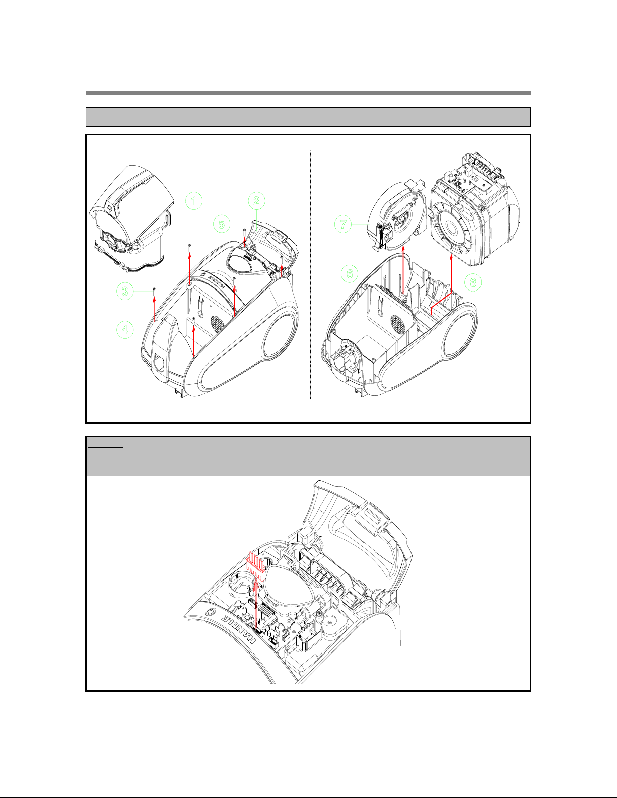
Be careful when breaking up the cord reel, the reelspring may spring out of the spring cover.
CAUTION
- 11 -

TROUBLE CAUSE CHECKING COUNTERMEASURE
Abrasion of the roller tire of cord reel Cord reel (See 5-4) Replace tire
Broken lever Cord reel (See 5-4) Replace lever
Lever spring broken away from cord reel bracket Cord reel (See 5-4) Repair lever spring
Bobbin is transformed Cord reel (See 5-4) Replace bobbin
Bracket is transformed Cord reel (See 5-4) Replace bracket
Lever is pushed by handle Cover (See 5-3) Repair handle
Brush does not rotate
any direction
Power cord does
not stop at an
arbitraty position
Clogged impurites in rotational part Brush (See5-10) Remove impurites
- 12 -

5. DISASSEMBLING AND TERATMENT
◈NOTE
First of all take cover top(5) out of cover Assy(4) and then take LED terminal out of main PCB
If do not remove LED terminal, main PCB may be damaged.
1) Remove dust box Assy(1) form body assembly(6).
2) Open cover filter(2) of cover Assy(4) then unscrew 6 screws(3).
3) Remove cover top(5) form cover assembly(4).
4) Remove cover Assy(4) from body assembly(6).
5) Remove cord reel Assy(7) and Motor Assy(8) from body assembly(6)
5-1. CLEANER ASSEMBLY
- 8 -

1) Check dust leakage between dust box(1) and clearner body(7) (Cause of defective motor).
2) Check inlet(9) of clearner body(7) clogged with dust (Cause of low suction power).
3) Check connection between wire connector(2) of cord reel and PCB (Cause of malfunction).
4) Check connection between wire connector(3) of motor and PCB (Cause of malfunction).
5) Check connection between wire connector(4) of body and PCB (Cause of malfunction).
6) Check connection between wire connector(5) of pressure switch and PCB (Cause of malfunction).
7) Check PCB circuit (Cause of of malfunction).
8) Check connection between hose adapter(10) and body(7) (Cause of malfunction).
- 9 -

1) Unscrew 3 screw(12) and separate socket(11) from body(1).
2) Remove socket(11) then separate Terminal(10) from socket.
3) Unscrew 1 screw(16) and remove switch pressure(15).
4) Cover Side(18) is separated by pulling outside and lift up.
5) Assembling is reverse order of disassembly.
1) Check Terminal assembly(10) (Cause of malfunction).
2) Check leakage between socket(11) and packing socket(9) (Cause of low suction power).
3) Check leakage between packing socket(9) and dust box (Cause of low suction power).
4) Check impurities in roller(4,5,6) (Cause of roller malfunction).
5) Check roller(4) (Cause of roller malfunction).
6) Check leakage between safety assembly(13) and body(1) (Cause of low suction power).
7) Check switch pressure (Cause of low suction power and malfunction).
5-2. BODY ASSEMBLY
- 10 -

1) Remove cover assembly from body.
2) Unscrew 2 screws(6) then remove handle(4) and stopper(5).
3) Separate button(2) form cover(1).
4) Unscrew 2 screws(10) then separate case pcb main assembly(9) form cover(1).
5) Assembling is reverse order of disassembly.
1) Check handle(4) (Cause of defective cord rewinding).
2) Check stopper(5).
3) Check button(2) (Cause of automatic cord rewinding).
4) Check cover filter(7) (Cause of defecitve cover closing).
5-3. COVER ASSEMBLY
- 11-

1) Separate cord reel assembly form body.
2) Separate plug of power cord(5) from bracket(11) and turn bobbin counterclockwise 4~5 times by holding plug.
Unscrew 1 screw(21).
3) Separate bobbin(1) from bracket(11).
4) Unscrew 2 screws(15) then separate wires(13,14) from supporter terminal(12).
5) Unscrew 2 screws(10) then separate cover sping assembly(9).
6) Unscrew 1 screw(6) then separate hole terminal(2~4) from bobbin(1).
7) Assembling is reverse order of disassembly. Make reserved winding 5 revolutions of bobbin clockwise
then assemble plug of power cord to bracket.
5-4. CORDREEL ASSEMBLY
CAUTION Be careful when disassembling the cord reel, the reelspring may spring
out of the spring cover.
- 12 -

1) Check connection between power cord and plug(5) (Cause of malfunction)
2) Check breaking of connection in power cord(1) (Cause of malfunction)
3) Check contact and abrasion between Y terminal(13,14) and ring terminal(3,4)
(Cause of malfunction)
4) Check connection between Y terminal(13,14) and wires (Cause of malfunction)
5) Check connection between terminal ring(3,4) and power cord.
6) Check spring(17) of lever (Cause of automatic rewinding by itself).
7) Check lever(16) (Cause of automatic rewinding by itself).
8) Check abrasion in tire(18) of stopper (Cause of automatic rewinding by itself).
9) Check reel spring assembly(9) is damaged (Cause of unwinding power cord).
10) Check power cord(5) is entangled in bobbin(1) (Cause of unwinding power cord).
11) Check fuse(14) (Cause of malfunction).
12) Check bobbin(1) is transformed (Cause of unwinding bobbin or noise)
- 13 -

1) Separate motor assembly from body.
2) Unscrew 8 screws(6) then separate case moto front(4) form case motor rear(5).
3) Separate packing motor(2), motor(1), mount motor(3) form case motor rear(5).
4) Assembling is reverse order of disassembly. Put motor wire in a hole of case motor rear(5) before assembling.
1) Check motor(1) brush is damaged (Cause of malfunction, noise or smell).
2) Check connection between motor(1) and wire (Cause of malfunction).
3) Check leakage between packing motor(2) and case motor front(4) (Cause of low suction power).
4) Check exhaust filter is clogged with dust (Cause of low suction power and high temperature of motor).
5) Check gasket(5-2, 5-6) (Cause of fine dust leakage).
5-5. MOTOR ASSEMBLY
- 14 -

1) Check filters(5,6) is polluted by dust (Casue of low suction power or bad smell).
5-6. FILTER EXHAUST ASSEMBLY
- 15 -

1) Unscrew 2 screws(30) then separate cover pipe(29). Separate knob(18), plate(17), button(31) and spring(32).
Unscrew 1 screw(16) then separate slide volume(15).
2) Unscrew 1 screw(34) then remove holder accessories(33).
3) Unscrew 1 screw(27) then remove holder hose(28) and separate cover terminal(26).
Unscrew 1 screw(24) then separate PCB assemble(22).
4) Separate wire of ring terminal assemble(21) from hose(8).
5) Unscrew 2 screws(13) then separate handles(11,12).
6) Unscrew 1 screw(7) then separate cover(6).
7) Assembling is reverse order of disassembly
5-7. HOSE ASSEMBLY
CAUTION Plsease do not remove assembly(8, 10, 19~20), before disassemble PCB(22).
If not do it, Y terminals in PCB Assy(22) may be damaged.
- 16 -

1) Check assembling states of knob ans slide volume (Cause of defective power control)
2) Check slide volume(15) (Cause of malfunction)
3) Check connection between slide volume(15) and wire (Cause of malfunction).
4) Check button(31) is damaged (Cause of defective holding of telescopic pipe)
5) Check connection between electronic wire(23) and PCB(22) (Cause malfunction).
6) Check soldering between Y terminal and PCB(22) (Cause of malfunction).
7) Check contact between Y terminal(22) and ring terminals(21)
(Cause of malfunction and noise of metal scratch)
8) Check connection between ring terminal(21) and wire of hose(8) (Cause of malfunction).
9) Check disconnection of wires in hose(8) (Cause of malfunction).
10) Check connection between terminals(2,3) and hose(8) (Cause of malfunction).
11) Check pipes(1, 14) and hose(8) are clogged with large object.
(Cause of low suction power and operation of electric safety device)
12) Check states of packing(20)
(Cause of low suction power, a air leakage(noise) or defective rotation of hose).
13) Check protrusion inside of cover terminal(26) (Cause of breakaway of hose and break of Y terminal).
14) Check button(4) is damaged (Cause of breakaway of hose from body).
15) Check holder accessaries(33) (Cause of breakaway of accessories).
- 17 -

1) Unscrew 3 screws(5) then separate cover box dust(1) form box dust(6). When separate cover box dust(1),
first disassemble central(rear) connection and then disassemble both sides(front) connection.
2) Unscrew 1 screw(5) then separate handle box dust(2) from cover box dust(1).
3) Separate guide(9) and door(14) from box dust(6).
4) Separate filter(8) and button(11) from box dust(6).
5) Separate cover box rear(15) from box dust(6) then separate button(18) and lever(20).
6) Separate filter assembly(22) from cover box rear(15).
7) Assembling is reverse order of disassembly
5-8. DUST BOX ASSEMBLY
- 18 -

1) Check clamp(3) (Cause of breakaway of box dust)
2) Check inside between guide air inlet(9) and box dust(6) clogged with large object or not.
(Cause of low suction power)
3) Check assemble state (a air leak or not) of gasket(10) of guide air inlet(9) and box dust(6)
(Cause of fine dust leakage)
4) Check assemble state of door(14) and box dust(6) (Cause of fine dust leakage)
5) Check button(11) (Cause of dust leakage).
6) Check frame filter(8) (Cause of malfuction of dust compression)
7) Check assemble state(a air leak or not) of cover box rear(15) and box dust(6).
(Cause of fine dust leakage)
8) Check lever(20) (Dust box assembly can't be assembled in the body properly
if assemble filter assembly incorrectly or if not filter assembly).
9) Check button(18) (Cause of dust leakage).
10) Check gasket(22-4) of filter assembly (Cause of fine dust leakage).
11) Check filter assembly(22) clogged with dust.
(Cause of low suction power and overheating of cleaner body →cause of lighting of dust meter).
- 19 -
Table of contents
Other Daewoo Vacuum Cleaner manuals

Daewoo
Daewoo RCU-3006 Series User manual

Daewoo
Daewoo HURRICANE CAT 5 User manual

Daewoo
Daewoo RCW-401 User manual

Daewoo
Daewoo RC-407 User manual

Daewoo
Daewoo RC-230 User manual

Daewoo
Daewoo RC-371BC User manual

Daewoo
Daewoo RC-6005B User manual

Daewoo
Daewoo DAC-20L User manual

Daewoo
Daewoo RCC-153R User manual

Daewoo
Daewoo RC-2200 User manual

Daewoo
Daewoo RCG-110 Series User manual

Daewoo
Daewoo RC-320F User manual

Daewoo
Daewoo RC-172 User manual

Daewoo
Daewoo RC-406 User manual

Daewoo
Daewoo CYCLONE ESSENTIAL User manual

Daewoo
Daewoo RCP-1000 User manual

Daewoo
Daewoo DCVC100 User manual

Daewoo
Daewoo RCC-231 User manual

Daewoo
Daewoo RC-370F User manual

Daewoo
Daewoo RCC-250F User manual