Dahua VTO2202F-P User manual

tel: +44 (0)1457 874 999 | fax: +44 (0)1457 829 201 | email: [email protected] | web: www.cop-eu.com
Please read this document before installation
VTO2202F-P
QUICK INSTALL
GUIDE
V1
Official UK distribution partner

2Tel: +44 (0)1457 874 999 | Fax: +44 (0)1457 829 201 | Email: [email protected] | Online: www.cop-eu.com
VTNS1060A
Switch
VTO2202F-P
Module
802.3af PoE 24v PoE
Tamper Switch Sounds an alarm in the event that the VTO unit is tampered with
Network Connection Connect the supplied RJ45 adapter cable to this port
+12v Used when not powering the VTO via PoE, connect the 12v or 24v DC positive supply to this
terminal
GND Ground connection for 12v DC negative supply and other inputs
12v Out DC 12v continuous output for auxiliary device (100mA max)
Door Button Input to connect a switch such as a push button for releasing the door lock
Door FB Input for door contact to check if the door is closed before engaging lock
Door NO/NC/COM Relay output used when unlocking door
RS485 A/B RS485 Bus for connecting secondary lock controller DEE1010B
Main VTH Monitor
VTH Passive PoE Monitor
Camera Module
When confi guring a home VDP system, all devices should fi rst be connected together. Usually, this is done by connecting both the
camera unit (VTO) and monitor unit (VTH) to the VTNS1060A PoE switch.
The VTNS1060A is a 24v passive PoE unit, this is a different type of PoE than that seen on conventional IP devices. As such, both the
VTO2000A and VTH1550CH can only be used with 24v passive PoE or by connecting a 12/24v DC power supply to the power input
terminals on the units.
Example 1
Example 2
HOME SYSTEM CONFIGURATION
VTO CONNECTIONS
PoE
Switch
Ethernet Link
VTNS1060A
Switch
802.3af PoE
24v PoE
PoE
Switch
Ethernet Link
Tamper
Switch
NET
Network
Connection
Inputs &
Outputs
GND
ALARM_COM
DOOR_FB
DOOR BUTTON
ALARM_ON
GND
DOOR_NC
DOOR_COM
DOOR_NO
12V_OUT
RS485_B
RS485_A
EOC1(+12)
EOC1(GND)

3
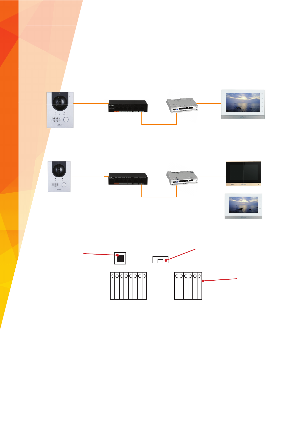
The fi rst step in confi guring the VTO cameras is to discover the cameras on the network so the IP address can be confi gured. By default
all VTO units are shipped on an IP address of 192.168.1.110 and in an uninitialised state.
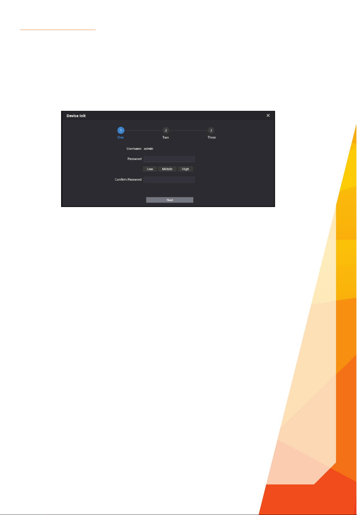
Before the VTO can be used and confi gured, the unit must fi rst be initialised. This can be achieved by connecting directly to the unit
via a web browser or using the VDP Confi g Tool in the Dahua Toolbox.
To initialise via the web browser, open Internet Explorer and type http://192.168.1.110 then follow the on screen prompts.
Please note: The computer IP address must be in the same IP subnet.
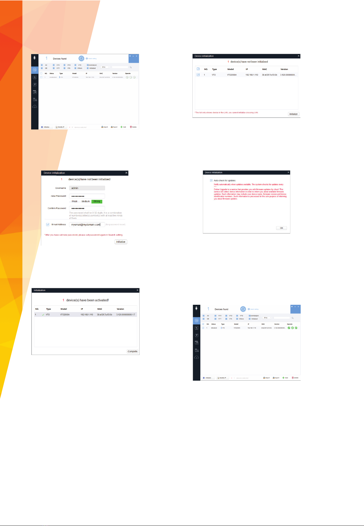
To initialise via the VDP Tool, fi rst download the Dahua Toolbox application and the VDP Tool.
Go to www.dahuasecurity.com, the toolbox application can be found using the top menu.
Go to Support > Download Center > Tools > Maintenance Tools.
Once the Toolbox application has been installed and opened, a list of smaller applications will be listed. Click install next to VDP Tool,
once the installation is complete, click Open to run the program.
With the VDP Tool open and the computer connected to the same network as the VTO, click the refresh icon at the top of the tool.
Any VDP devices connected to the computer directly or via a switch should now be displayed.
INITIALISATION

4Tel: +44 (0)1457 874 999 | Fax: +44 (0)1457 829 201 | Email: [email protected] | Online: www.cop-eu.com
1. Check the box next to the VTO to be initialised. 2. Click the initialise button to start the initialise process.
3. Enter the new password to be used for the VTO
and an email address for password recovery. Set
P/N to P and click next to continue.
4. Check or Uncheck Online update options. A direct
internet connection is required for these features.
5. After a few seconds the tool should show that the
VTO was successfully initialised. Click Finish to end
the process.
6. The VTO will now show in the Confi g Tool in an
initialised state. It is now possible to program the
VTO IP address and other settings. You must ensure
the password is modifi ed to the initialised password
of the VTO within the search setting, located at the
top of the confi g tool.

5
Once logged in to the VTO, Go to Local Setting
Change Device Type to Villa Station
Click Confi rm to save the setting.
Login to the VTO via the computers web browser using the username of “admin” and the password entered during the initialisation
stage.
VTO Camera Confi guration
HOME SYSTEM CONFIGURATION

6Tel: +44 (0)1457 874 999 | Fax: +44 (0)1457 829 201 | Email: [email protected] | Online: www.cop-eu.com
Before confi guring the VTH it must fi rst be initialised. Follow the on screen wizard to set an admin password. The password can only
be made up of numbers.
To confi gure the VTH unit use the built in menu within the monitor itself. VTH units do not support web browser confi guration.
Hold down the Settings button for 5 seconds and enter the admin password set during the initialisation wizard.
If the settings button is only pressed and not held, entering the password 123456 will enter the user settings rather than engineer
settings.
In the settings menu select Network to confi gure the VTH network settings. When confi guring the network address of the VTH it is vital
to ensure the IP address range is within the same Subnet as the VTO.
VTH Monitor Confi guration

7
The VTH Confi g menu is used to set the room number of the VTH and to confi gure the unit as a Master or Extension unit. If only a single
VTH is being used in the system, then this should be set to Master and a room number chosen. Adding extension VTH units is covered
on page 9. Note: Master monitor must have #0 after the room number.
In the settings menu select SIP to confi gure the VTH SIP settings. Enter the IP address of the VTO and also a register password of your
choosing, it is important to remember this password as it will be used again later.
For both the VTO and VTH to communicate, each unit must have the IP address details of the other unit. To add the VTO unit to the
VTH, select VTO Confi g and input the VTO units IP address, Username & Password then set Enable Status to ON.
Set Enable Status to ON and tap OK

8Tel: +44 (0)1457 874 999 | Fax: +44 (0)1457 829 201 | Email: [email protected] | Online: www.cop-eu.com
To add the VTH to the VTO, revisit the VTO web browser and go to Household Setting > Room No Management. Click Clear to
remove the rooms already added into the system by default.
Click Add and enter the connection details for the VTH monitor such as Resident name and the register password chosen earlier.
Please refer to page 6.
Click Save
At the top of the VTH screen the icon should disappear, this indicates that the VTO and VTH are now connected.
If the icon is still displayed, go back to the VTH menu > VTO Confi g and Disable then re-enable the Status option.
To call the VTH from the VTO, press the button on the VTO unit and press Answer to initiate two way communication.

9
Additional VTH monitors can be added to the system as Extension monitors. These monitors can then be called simultaneously along
with the Master monitor. Up to 9 extension monitors can be added to each master monitor.
To enable this feature and confi gure the additional VTH units;
Login to the VTO web browser and go to Local Setting > Basic and tick the Group Call option.
Click Confi rm to save the setting
On the additional VTH unit, fi rst confi gure the network address within the same range as both the VTO and existing VTH units.
Go to Settings > VTH Confi g and select Master, this will change the VTH to Extension mode. Input the room number of the master unit
followed by #1, as an example if the room number is 1 enter 1#1 or 1#2, 1#3 etc. for further additional units.
Note: When using Extension monitors, the Master monitor room number must have #0 included. For example 1#0
In the Master IP fi eld enter the IP address of the main VTH unit.
The master name must be admin and the master password must be the engineer password of the master monitor.
Select OK to save the setting, the confi guration is now complete.
Adding Extension VTH Units

10 Tel: +44 (0)1457 874 999 | Fax: +44 (0)1457 829 201 | Email: [email protected] | Online: www.cop-eu.com
iDMSS - Free
iPhone
gDMSS - Free
Android Phone
iDMSS HD- Free
iPad
gDMSS HD - Free
Android Tablet
Connect using the app
2. Select Home
5. Select SN/Scan.
1. Open DMSS app.
4. Tap +
3. Tap the Device List
icon.
6. Scan the QR Code for the
VTO in the Network Setting
page of the web browser
Currently P2P is only supported for iOS and Android devices.
Download the mobile application to your mobile device by scanning the QR codes below or by searching for the app in your relative
app store.
APPLICATION SET UP

11
2. Select Notifi cation icon
8. Select VTO from the list
of Device types
1. Select Message icon
7. Confi rm the serial
number presented on
screen matches the serial
number of the VTO and
click Next
3. Enable Subscribe for
the device.
9. Enter a name for the
device and password,
click the Save icon
Confi gure Push Notifi cations
10. Tap Live preview to
view the camera stream
4. VTO Events will now be
pushed to the app

COP UK, Delph New Road, Dobcross, OL3 5BG England
Table of contents