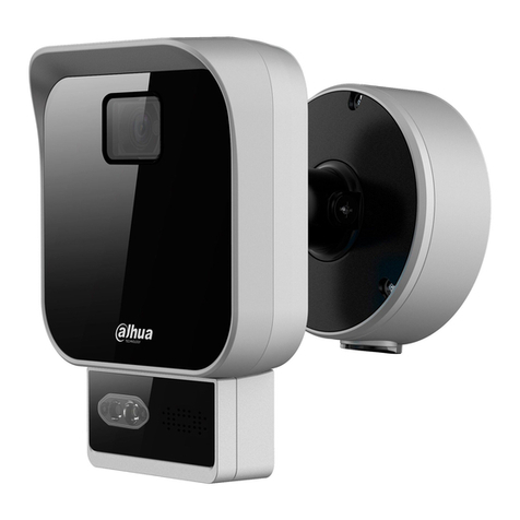
Dahua DHI-ITSJC-2302-DC12 User manual

79GHz Anti-smashing Radar
User’s Manual
V1.0.0
V1.0.0
ZHEJIANG DAHUA VISION TECHNOLOGY CO., LTD.

User’s Manual
I
Foreword
General
This manual introduces the functions and operations of the 79GHz anti-smashing radar
(hereinafter referred to as the "Radar").
Models
DHI-ITSJC-2302-DC12
DHI-ITSJC-2202-DC12
Safety Instructions
The following categorized signal words with defined meaning might appear in the manual.
Signal Words
Meaning
DANGER
Indicates a high potential hazard which, if not avoided, will result
in death or serious injury.
WARNING
Indicates a medium or low potential hazard which, if not avoided,
could result in slight or moderate injury.
CAUTION
Indicates a potential risk which, if not avoided, could result in
property damage, data loss, lower performance, or unpredictable
result.
TIPS
Provides methods to help you solve a problem or save you time.
NOTE
Provides additional information as the emphasis and supplement
to the text.
Revision History
Version
Revision Content
Release Time
V1.0.0
First release.
March 2020
About the Manual
The manual is for reference only. If there is inconsistency between the manual and the
actual product, the actual product shall prevail.
We are not liable for any loss caused by the operations that do not comply with the manual.
The manual would be updated according to the latest laws and regulations of related
jurisdictions. For detailed information, refer to the paper manual, CD-ROM, QR code or our

User’s Manual
II
official website. If there is inconsistency between paper manual and the electronic version,
the electronic version shall prevail.
All the designs and software are subject to change without prior written notice. The product
updates might cause some differences between the actual product and the manual. Please
contact the customer service for the latest program and supplementary documentation.
There still might be deviation in technical data, functions and operations description, or
errors in print. If there is any doubt or dispute, we reserve the right of final explanation.
Upgrade the reader software or try other mainstream reader software if the manual (in PDF
format) cannot be opened.
All trademarks, registered trademarks and the company names in the manual are the
properties of their respective owners.
Please visit our website, contact the supplier or customer service if there is any problem
occurring when using the device.
If there is any uncertainty or controversy, we reserve the right of final explanation.

User’s Manual
III
Important Safeguards and Warnings
This chapter describes the contents covering proper handling of the Radar, hazard prevention,
and prevention of property damage. Read these contents carefully before using the Radar,
comply with them when using, and keep the manual well for future reference.
Operation Requirements
Make sure that the barrier will not jitter obviously, and when installing guardrail at one side
of the lane, secure the guardrail to prevent it from moving back-and-forth or jittering.
After installing the Radar, please insulate the exposed cable cores.
Install the Radar 60 cm (23.6'') away from the ground (70 cm (27.6'') is recommended
when large trucks are frequently seen).
Do not impact the Radar. Prevent the Radar from falling down.
Do not place metal objects in the range of 0.5 m (1.6 ft) right in front of the Radar.
Guardrails and speed bumps that might contain metal elements should be installed as far
away from the Radar as possible.
Do not dissemble the Radar.
Clean the surface of the Radar with a soft dry cloth or a clean soft cloth dipped in neutral
detergent, and then dry the surface.
WARNING
Use accessories suggested by the manufacturer, and install and maintain the Radar by
professionals.
When using a laser beam device, avoid exposing the device surface to laser beam
radiation.
Do not provide two or more than two kinds of power supply modes; otherwise, the Radar
might be damaged.
Power Requirements
Improper battery use might result in fire, explosion, or inflammation.
When replacing battery, make sure that the same model is used.
Use the recommended power cables in the region and use them under the rated
specification.
Use the power adapter provided with the Radar; otherwise, it might result in people injury
and device damage.
The power source shall conform to the requirement of the Safety Extra Low Voltage (SELV)
standard, and supply power with rated voltage which conforms to Limited power Source
requirement according to IEC60950-1. Note that the power supply requirement is subject
to the device label.

User’s Manual
IV
Connect device (type-I structure) to the power socket with protective earthing.
The appliance coupler is a disconnection device. Keep a convenient angle when using it.
Application Environment Requirements
Do not aim the Radar at strong light (such as lamplight, sunlight) for focusing.
Transport, use and store the Radar under the allowed humidity and temperature
conditions.
Prevent any liquid from flowing into the Radar.
Install the Radar in a well-ventilated place, and do not block the ventilation of the Radar.
Do not press, vibrate or soak the Radar during transportation, storage and installation.
Pack the Radar with packaging materials provided by its manufacturer or materials with the
same quality before transporting it.
It is recommended to use the Radar with a lightning-proof device for better lightning-proof
effect.
Ground the Radar to improve its reliability.

User’s Manual
V
Table of Contents
Foreword.................................................................................................................................................... I
Important Safeguards and Warnings.................................................................................................... III
1 Product Introduction............................................................................................................................. 1
Overview....................................................................................................................................... 11.1 Features........................................................................................................................................ 11.2
2 Appearance and Structure ................................................................................................................... 2
Appearance................................................................................................................................... 22.1 Dimensions ................................................................................................................................... 22.2
3 Installation.............................................................................................................................................. 3
Tools.............................................................................................................................................. 33.1 Installation Method........................................................................................................................ 33.2 3.2.1 Radar for Triggering Snapshot ........................................................................................... 3
3.2.2 Radar for Anti-smashing..................................................................................................... 5
Wiring............................................................................................................................................ 73.3 3.3.1 Cable Description ............................................................................................................... 7
3.3.2 Cable Connection............................................................................................................... 8
4 Configuration on Mobile App............................................................................................................... 9
Connecting Your Phone to Radar Wi-Fi........................................................................................ 94.1 Connecting App to Radar.............................................................................................................. 94.2 4.2.1 Setting Radar Parameters................................................................................................ 10
4.2.2 Upgrading Firmware......................................................................................................... 12
4.2.3 Modifying Wi-Fi Information.............................................................................................. 12
4.2.4 Viewing Real-time Data.................................................................................................... 13
5 Commissioning ................................................................................................................................... 15
Radar for Anti-smashing ............................................................................................................. 155.1 Radar for Triggering Snapshot.................................................................................................... 155.2
6 FAQ ....................................................................................................................................................... 16
Cybersecurity Recommendations................................................................................... 17Appendix 1

User’s Manual
1
1 Product Introduction
Overview1.1
The 79GHz anti-smashing radar adopts leading technologies of high-precision microwave
measurement and high-speed digital signal processing, endowing it with high accuracy, free of
commissioning, and high stability. The radar is ideal for working with boom barrier to monitor
and control vehicles that enter and leave, and prevent the barrier arm from hitting people or
vehicles when it falls. It can also work with the camera to read and recognize license plate,
providing reliable evidence for parking management.
The Radar sends the information of detection target to the host computer or central platform
through RS-485 communication or Wi-Fi, so the real-time information can be displayed on the
computer or the platform. It can also send the information to the relay to trigger the camera for
taking snapshots, and helps control barrier opening and closing.
Features1.2
79GHz monolithic microwave integrated circuit (MMIC) technology allows higher resolution
and more stable detection.
Uses the latest algorithm to filter interference, suitable for advertising barriers, fence arm
barriers, straight arm barriers, and folding arm barriers.
Uses MIMO (multiple-input multiple-output) technology to recognize movement directions
of targets, ideal for scenes with both vehicles and people entering and leaving.
Adjustable detection distance and width, and no need of reading scene data, applicable to
complicated scenes.
Supports upgrading through RS-485 and mobile app (with Wi-Fi connection), and allows
online commissioning and firmware upgrade, providing ease of operation.
Convenient installation and maintenance: Compared with coils, you can easily installed the
Radar by tightening the screws, with no need of road construction.
Capable of identifying vehicles and people, preventing the barrier arm from hitting the
vehicles and people.
Long service life of 5–10 years.
Two LED indicators are designed to better know the working status of the Radar: Red for
power, and green for activity.
Solid red: Power is supplied.
Solid green: Target is detected. When the target leaves, the green indicator turns off.
Automatically goes to the last working status before it is powered off.
Adaptable to harsh environments, and its detection performance will not be influenced by
electromagnetic interference, light, dust, rain, and snow.

User’s Manual
2
2 Appearance and Structure
Appearance2.1
AppearanceFigure 2-1
Dimensions2.2
Dimensions (mm [inch])Figure 2-2

User’s Manual
3
3 Installation
Tools3.1
Hole opener, Phillips screwdriver, straight screwdriver, wire stripper, RS-485 cable, and PC.
Extra tools needed when installing radar for triggering snapshot: Impact driver, M10 drill, and
wrench.
Installation Method3.2
The Radar, either used for triggering snapshots or anti-smashing, needs to be installed vertical
to the lane direction. Install the anti-smashing radar on the casing of the boom barrier, and
when the Radar is used for triggering snapshots, install it on a pole, with the lower side of the
Radar 0.6 m (2.0 ft) away from the ground.
Installation exampleFigure 3-1
When installing the Radar on the casing of the barrier, the casing must be stable (jittering
angle no more than 5°) to ensure the detection accuracy of the Radar.
When installing guardrail at one side of the lane, secure the guardrail to prevent it from
moving back-and-forth or jittering.
3.2.1 Radar for Triggering Snapshot
Install the mounting pole.Step 1 1) Install the mounting pole on the same side with the license plate recognition
camera.
2) Mark four holes on the ground according to holes of the mounting pole, and then
use M10 drill to drill four 50 mm (2.0'') holes in the ground based on the marks.
3) Use four M6 expansion screws to fix the mounting pole to the ground. Put the
cover in place.

User’s Manual
4
Install the mounting poleFigure 3-2
Install the Radar.Step 2 1) Install the Radar 60 cm (23.6'') away from the ground (70 cm (27.6'') is
recommended when large trucks are frequently seen).
2) Fix the rear plate of the Radar to the mounting pole by using 4 flange screws.
3) Fix the Radar to the rear plate by using two M4 screws. See Figure 3-3 and Figure
3-4. Install the RadarFigure 3-3
Installation completedFigure 3-4

User’s Manual
5
3.2.2 Radar for Anti-smashing
Drill holes.Step 1 1) Drill a Φ23 mm (0.9'') circular hole (hole A) on the casing of the advertising barrier
and at a height of 68 cm (26.8'') from the ground (78 cm (30.7'') is recommended
when large trucks are frequently seen).
2) Drill two Φ5 mm (0.2'') circular holes (holes B and C). The distance between holes
A and B is 39 mm (1.5''), and the distance between holes A and C is 85 mm (3.3'').
Hole size (mm)Figure 3-5
Fix the Radar.Step 2 1) Install waterproof joints between the Radar and the casing of the barrier. See
Figure 3-6.
2) Fix the Radar to the casing through holes B and C by using screws.
3) Connect radar cables to the barrier through hole A. See Figure 3-7.
For the installation result, see Figure 3-8.

User’s Manual
6
Waterproof joint installationFigure 3-6
1: Front cover; 2: Rear cover; 3: Waterproof joint
Fix the RadarFigure 3-7
Installation completedFigure 3-8

User’s Manual
7
The Radar can be installed either on the barrier casing or the mounting pole. See
Figure 3-9. For both of the installation methods, the Radar needs to be installed within
50 cm (19.7'') of the barrier arm. Right Width and Left Width should be more than 0.5
m (1.6 ft) to avoid interference from the barrier arm and ensure radar detection
accuracy. You can set the widths on the mobile app STJ79 (see "4.2.1 Setting Radar
Parameters"). Radar installation methodsFigure 3-9
Install the Radar on mounting pole Install the Radar on barrier casing
Wiring3.3
3.3.1 Cable Description
CableFigure 3-10

User’s Manual
8
Table 3-1 Cable description
Cable
Description
J1-1 (brown), J1-2 (yellow)
Relay output.
J2-1 (white), J2-2 (purple)
Program loading control, barrier closing signal input.
T/R- (blue), T/R+ (green)
RS-485 communication.
GND (black), +12V (red)
12V power output.
3.3.2 Cable Connection
Connect the Radar to power: Connect +12V (red) and GND (black) to positive and
negative terminals of power source respectively. A solid red indicator on the Radar
indicates that the power supply is normal.
Connect the Radar to camera:
Alarm: Connect J1-1 (brown) and J1-2 (yellow) to alarm output ports of camera.
RS-485 communication: Connect T/R- (blue) and T/R+ (green) to RS-485 ports of the
camera, and then connect the RS-485 cable to computer serial port.
Connect to barrier: Connect J1-1 (white) and J1-2 (purple) to the I/O and COM ports of the
barrier.
Upgrade radar firmware: Connect J2-1 (white) and J2-2 (purple) to the push button. When
connecting the radar to barrier, you can also connect J2-1 (white) and J2-2 (purple) to
closing signal input port of the barrier.

User’s Manual
9
4 Configuration on Mobile App
Connecting Your Phone to Radar Wi-Fi4.1
After connecting the Radar to power, enable WLAN of your phone from Settings > WLAN,
select AWHST_DZ_01 and enter the Wi-Fi password (123456789 by default).
Wi-Fi connectionFigure 4-1
Connecting App to Radar4.2
Scan the QR code provided in the accessory to download and install the STJ79 app,Step 1 and an icon is generated on the desktop of your phone.
Open the app, and then tap WiFi Connection. The app is successfully connected toStep 2 the Radar. Now you can start setting radar parameters.
Tap at the upper-right corner, and then tap Instructions to view help.

User’s Manual
10
Wi-FiconnectionFigure 4-2
4.2.1 Setting Radar Parameters
In the Parameter section, tap Basic Parameter Setting and Advanced Parameter Setting to
set the parameters. Set basic parametersFigure 4-3

User’s Manual
11
Set advanced parametersFigure 4-4
Table 4-1 Set basic and advanced parameters
Type
Name
Description
Basic
Parameter
Max Range
The maximum detection range of the Radar, generally the length
of the barrier arm or lane width. Value range: 0.3–6.0 (3.0 by
default).
Falling Time
Set this parameter only when the Radar is used for
anti-smashing.
Set falling time according to the time that the barrier arm takes to
rise and then fall. The value is 6 s by default, and it does not
affect the opening/closing speed of the barrier.
Mode
Select mode according to the actual installation position of the
Radar.
Advanced
Parameter
Left Width
Detection width at the left or right side of the radar normal line.
Value range: 0–1.0 (1.0 by default).
How to tell the left or right side: The left or right side of the Radar
when you face the Radar and the indicator lights are at the upper
side.
Right Width
Min Range
The range filtered by the Radar. Value range: 0.3–6.0 (0.3 by
default). Suitable for setting the minimum range when there is
interference near the Radar.
Sensitivity
Reserved parameter. Keep the default value (0.3).
DPV
DPV means distinguishing people and vehicles.
Yes: The Radar will detect only vehicles.
No: The Radar will detect both people and vehicles.
Direction
Set this parameter only when the Radar is used for triggering
snapshots.
Select direction according to the approaching direction of
vehicles. The Radar can only detect vehicles approaching from
the selected direction.

User’s Manual
12
4.2.2 Upgrading Firmware
In the Update section, tap Select Firmware to select firmware of interest, and then tap Update.
The firmware upgrade starts.
Standby Mode is recommended when the above upgrade method failed or the Radar crashed.
Firmware upgradeFigure 4-5
4.2.3 Modifying Wi-Fi Information
In the SysInfo section, tap WiFi, and then tap the corresponding item to view or modify the
Wi-Fi account or password.

User’s Manual
13
View and modify Wi-Fi informationFigure 4-6
4.2.4 Viewing Real-time Data
In the SysInfo section, tap Open, and then you can view the real-time detection data. If a target
is detected, a green dot will show at the target’s position. See Figure 4-7. If the green indicator
keeps on (meaning target is detected) after the Radar is installed, you can check whether there
is interference in the detection range according to the actual conditions near the Radar. If yes,
adjust the Min Range (see Table 4-1) to filter out the interference and ensure detection
accuracy.

User’s Manual
14
View real-time dataFigure 4-7
This manual suits for next models
1
Table of contents
Other Dahua Radar manuals