4. Doorhanginghrackets
The door hanging brackets are made of iron and are connected to the door with bolts. Each
pulley has a greased, sealed ball bearing and a plastic tire. The rail is extruded
aluminum.
For installation on fire doors, the pulley tires and rail are made of iron (EDM-30Z)
BOilary opon
.~I
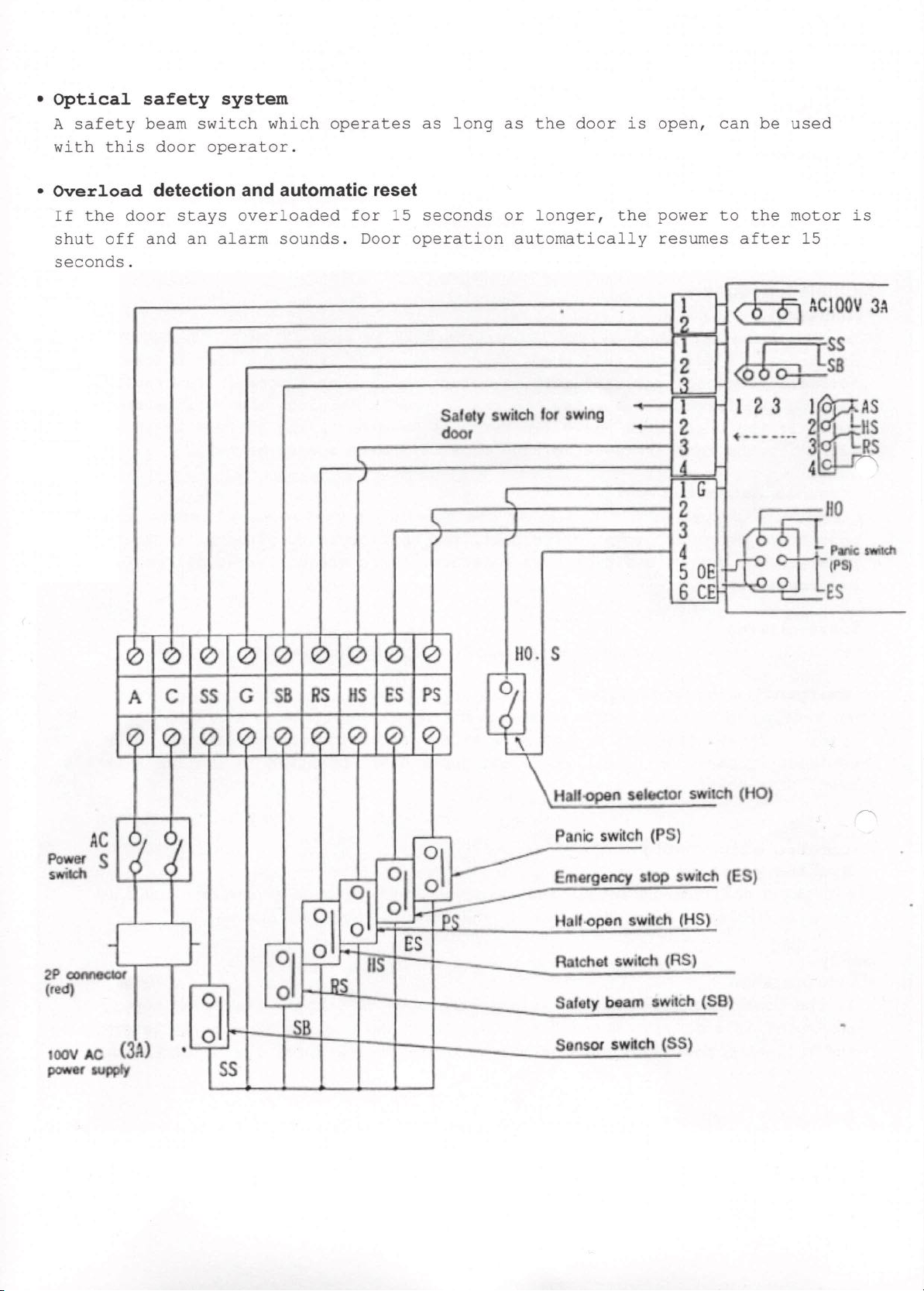
Panic switch
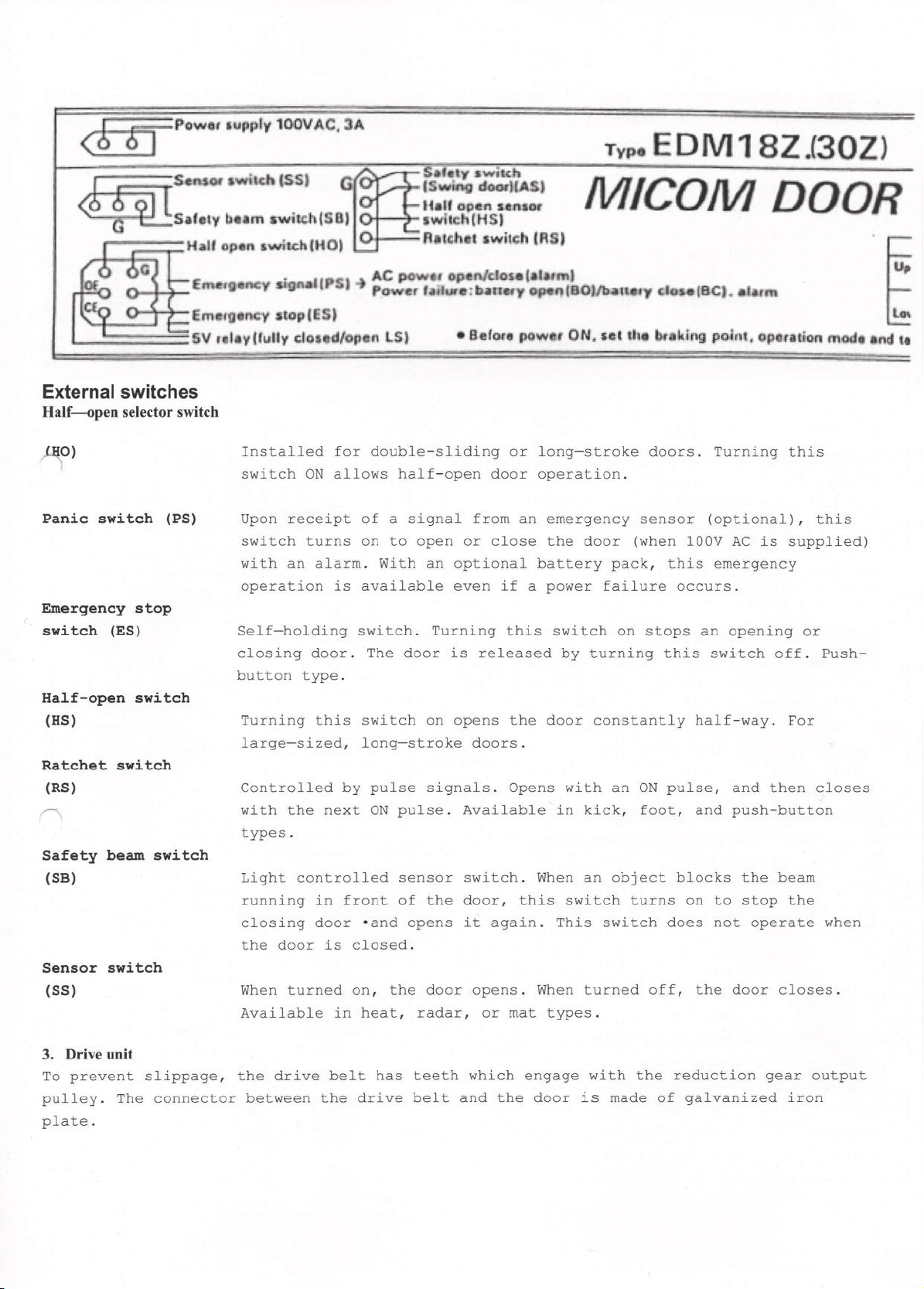
5. Sensor switch
Sensor switches are available in
various types: heat, radar, infrared,
ultrasonic, electronic mat, rubber
mat, touch, loop coil, push-button,
etc. Choose the one the most suited to
the installation site.
6. Optional systems Battery-open system
(BOZ)
The door opens fully with an alarm
when a power failure occurs. (Power
supply to the motor continues for 25
seconds.
l00V IIC
Con1rOl box
,
DC_
M
BatIOry pad<
(0Cz4V )
I
-----7'-->
I
Open
r
Battery-close system (BCZ)
The door closes fully with an alarm
when a power failure OCCUrS. The door
is then press-closed until the battery
is exhausted (approx. 30 minutes) .
This system is useful for fire doors.
Ba,." -..
<--~._._.-
Close
loc~
control bo.•
lOOV IIC
DC molar
Electromagnetic lock system (Li Z)
(unlocking upon receipt of power supply)
When the sensor switch turns on and
power is supplied, the door is
unlocked. The door is automatically
locked when fully closed. When there
is no power supply or when a power
failure occurs, the door is locked.
Electromagnetic lock system (L2Z) (locking
upon receipt of power supply)
When sensorswitchturnson andpower iscutoffthe
doorisunlocked. The door is automatically
lockedwhen fullyclosed. When there is no
power supply or when a power failure
occurs, the door is unlocked.
,.-
• (L1)
I
lO<ll convol boo
~ed ••hen
Of.oII