Daikin ZH(C)3LSF User manual

Head office:
Umeda Center Bldg., 4-12, Nakazaki-Nishi 2-chome,
Kita-ku, Osaka, 530-8323 Japan
Tokyo office:
Shinjuku Sumitomo Bldg., 6-1 Nishi-Shinjuku
2-chome, Shinjuku-ku, Tokyo, 163-0235 Japan
Zandvoordestraat 300, B-8400 Oostende, Belgium
«The specifications, designs, and information in this manual are subject to change without notice.
Printed in Japan 02/2003 AK
Semi-Hermetic Single Screw
Compressor Version
For Overhaul and Inspection
[Applied Models]
ZH(C)3LSF ZH3LMF ZH(C)3LTG
ZH(C)5MLF ZH5SLF ZH(C)3WLG
ZH(C), (A)5LLF ZH5LMF ZH(C), (A)5LMG
ZH(C), (A)7SLF ZHA7MLF ZH(C), (A)5WLG
ZH(C)7LLF ZHA7MSGZH(C)7LSG
ZH(C), (A)9SLF ZH(C), (A)7WSG
ZH(C), (A)9LLF ZH(C), (A)9LSG
ZH(C), (A)9WSG
Si50-203

Si50-203
Semi-Hermetic Single Screw Compressor Version III 1
Semi-Hermetic Single
Semi-Hermetic SingleSemi-Hermetic Single
Semi-Hermetic Single
Screw Compressor
Screw CompressorScrew Compressor
Screw Compressor
Version III
Version IIIVersion III
Version III
1. Scope of Application ...............................................................................2
2. Overhaul..................................................................................................3
3. Periodic Inspection..................................................................................4
3.1 Periodic Inspection Items and Intervals....................................................4
3.2 Periodic Inspection Instructions................................................................5
4. Overhaul Instructions ............................................................................10
4.1 Disassembly and Inspection...................................................................11
4.2 Replacing The Bearing...........................................................................20
4.3 Final Assembly .......................................................................................24
5. Airtightness Test ...................................................................................29
6. Charging Oil ..........................................................................................30
7. Caution in Test Operation .....................................................................31
8. Required Tools......................................................................................32
[Applicable Models]
ZH3LSF ZH3LMF ZHC3LSF ZH3LTG ZHC3LTG
ZH5MLF ZH5SLF ZHC5MLF ZH3WLG ZHC3WLG
ZH5LLF ZH5LMF ZHC5LLF ZHA5LLF ZH5LMG ZHC5LMG ZHA5LMG
ZH7SLF ZHC7SLF ZHA7SLF ZH5WLG ZHC5WLG ZHA5WLG
ZH7LLF ZHC7LLF ZHA7MLF ZH7LSG ZHC7LSG ZHA7MSG
ZH9SLF ZHC9SLF ZHA9SLF ZH7WSG ZHC7WSG ZHA7WSG
ZH9LLF ZHC9LLF ZHA9LLF ZH9LSG ZHC9LSG ZHA9LSG
ZH9WSG ZHC9WSG ZHA9WSG

Scope of Application Si50-203
2 Semi-Hermetic Single Screw Compressor Version III
1. Scope of Application
This booklet applies to semi-hermetic single screw compressor for use in Model F type (ZH_F),
G type (ZH_G). Replacement intervals specified in the booklet are empirically worked out
based on the design service life expected of the compressors operated under the design
conditions, and are intended to provide a general guide by which to formulate a maintenance
plan.

Si50-203 Overhaul
Semi-Hermetic Single Screw Compressor Version III 3
2. Overhaul
Generally, maintenance and inspection of equipment are important in preventing their failure
and damage to them. Equipment, even without defective structure or components, gradually
age and wear over long years of operation. For example, screw compressors, despite their
apparent good operating condition, may face such problems as decreasing insulation resistance
of the motor, oil deterioration, and worn and fatigued bearings during long periods of operation.
Most of such changes with time are invisible from the outside in many cases, and it is only after
an accident that they are noticed. For this reason, in the case of equipment required to be
highly reliable, it is most important to grasp their wear condition precisely and take necessary
measures against accidents if they are to maintain proper operating conditions for expanding
service life.
Overhaul interval: 40,000 hours or 7 years, whichever comes first.

Periodic Inspection Si50-203
4 Semi-Hermetic Single Screw Compressor Version III
3. Periodic Inspection
“Periodical Inspection” means to inspect, adjust and clean various parts of devices and
equipment at the scheduled interval.
3.1 Periodic Inspection Items and Intervals
Table 3-1 shows periodic inspection items and intervals. Conduct inspections at the earliest
indicated inspection intervals.
Table 3-1 Periodic inspection items and intervals
No. Item Inspection
1Measurement of motor insulation
resistance 1 year
2 Inspection of refrigeration oil 7,500 hr or 4 years
3 Inspection of gate rotor 20,000 hr or 4 years
4 Inspection of suction filter 20,000 hr or 4 years

Si50-203 Periodic Inspection
Semi-Hermetic Single Screw Compressor Version III 5
3.2 Periodic Inspection Instructions
1. Insulation Resistance of The Motor
!Insulation Resistance Testing
A megger is used to apply voltage directly to an insulated object, measure leakage current
through the insulated object, and find the insulation resistance values. Its scale is voltage /
leakage graduated with such insulation resistance values.
The following equation holds:
Insulation resistance = applied voltage / leakage current
Note: 1. A megger indicates an increasing resistance value with time, because absorption current
flows through the insulated object at an early stage, lowering the resistance value
correspondingly.
2. Prohibit anyone from measuring insulation resistance in a vacuum.
It must be measured at atmospheric pressure or after the filling of refrigerant. The reason
is that in a vacuum, the insulation ability of gas lowers, and thus electric discharge is apt to
occur.
(Measuring Procedure)
(1) Turn off the main power and operating power.
(2) Remove the terminal cover.
(3) Before measurement, disconnect the cables connected to the compressor or control panel.
(4) Disconnect the CTP protector lead wire.
(5) Conduct measurement.
Fig. 3-1 Motor insulation resistance measuring method
(Measurement Standard)
Using a 500-V megger. The measured value shall be 3 MΩor higher.

Periodic Inspection Si50-203
6 Semi-Hermetic Single Screw Compressor Version III
2. Changing Refrigerating Oil
Oil degrades after many hours of operation and due to aging. Replace oil regularly after
7,500 hours of operation or four years, whichever comes first.
(Changing Procedure)
(1) Perform a pump down operation to reduce pressure inside the compressor.
(2) Release the internal pressure of the compressor.
Loosen the flare nut at the service port (with check valve) of the compressor (see Fig. 3-2).
Remove the partition lid, then tighten the flare nut to discharge refrigerant from the
compressor. To loosen and tighten the flare nut, use two wrenches to turn the flare nut and
keep the other nut stationary.
Fig. 3-2 Service port and oil charge port locations
(3) After confirming that refrigerant is completely discharged, drain oil from the two drain ports
located on the lower section of the casing.
The compressor rotates in the reverse direction when it stops operating. This causes oil to
remain in the suction side. Therefore, be sure to drain oil from the two drain ports.
Fig. 3-3 Drain port locations

Si50-203 Periodic Inspection
Semi-Hermetic Single Screw Compressor Version III 7
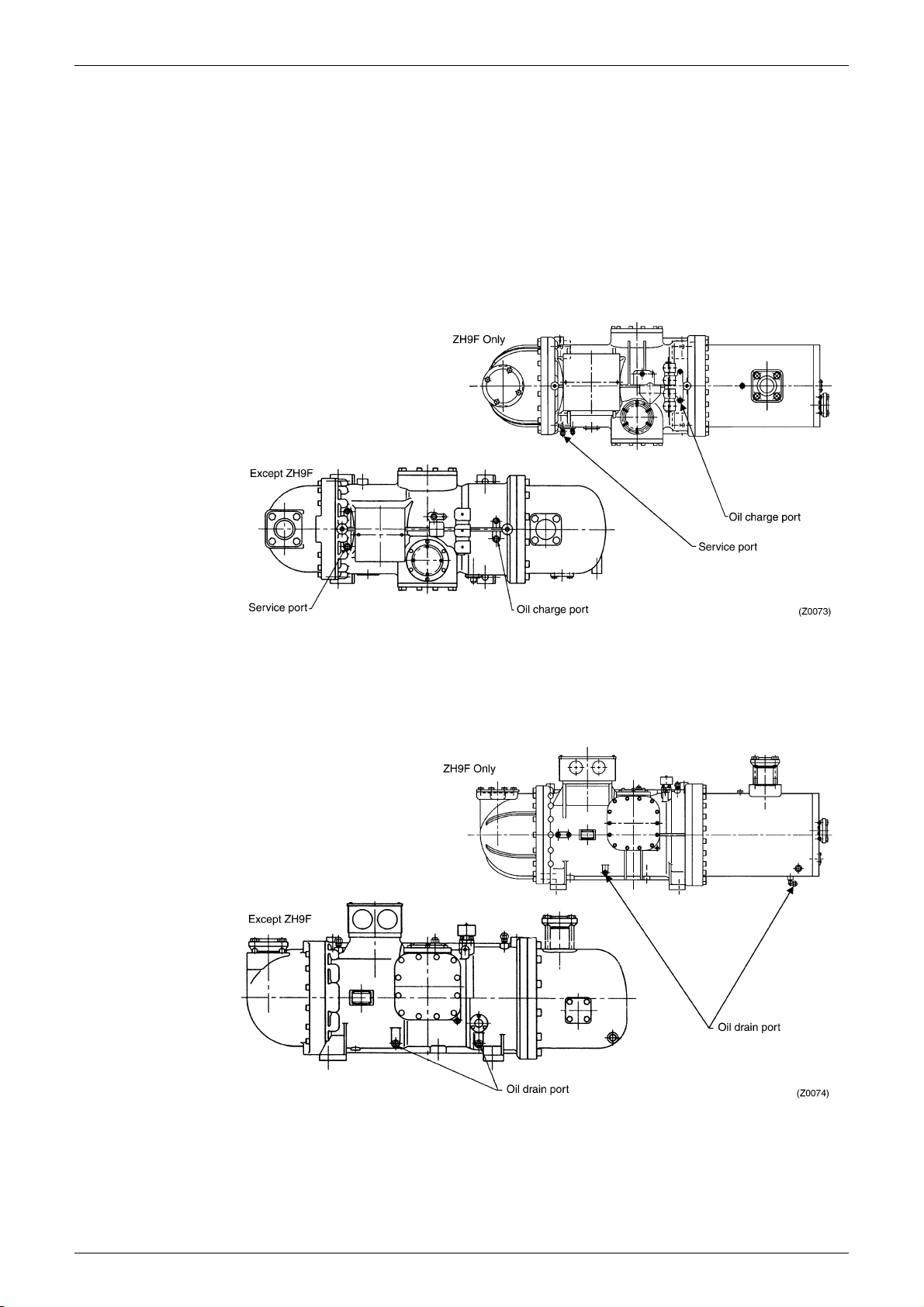
(4) Charging oil
Connect a vacuum pump to the suction service port (1/4" DCut) on the casing. While
evacuating the compressor, add oil from the discharge service port (3/8" DCut).
Use SUNISO 4GSD refrigeration oil (possible for use equal product) for refrigerant R22
and DAPHNE FVC68D refrigerant oil for refrigerant R407C and R134a.
Add the same amount of new oil as drained because some remains in the refrigerant and
on various parts inside. Drained oil contains refrigerant and appears to be more in
volume than actual oil amount. Stir the oil to evaporate the dissolved refrigerant before
measuring. Do not add more oil than necessary, since an excessive amount of oil
reduces oil separation efficiency and causes system problems. (Oil surface should be
visible on the level gauge during equipment operation.)
Take care not to let in air, or dust and other foreign particles remaining on the bottom of
the oil container.
When charging oil from a previously opened container, conduct vacuuming of the
compressor to remove moisture and air.
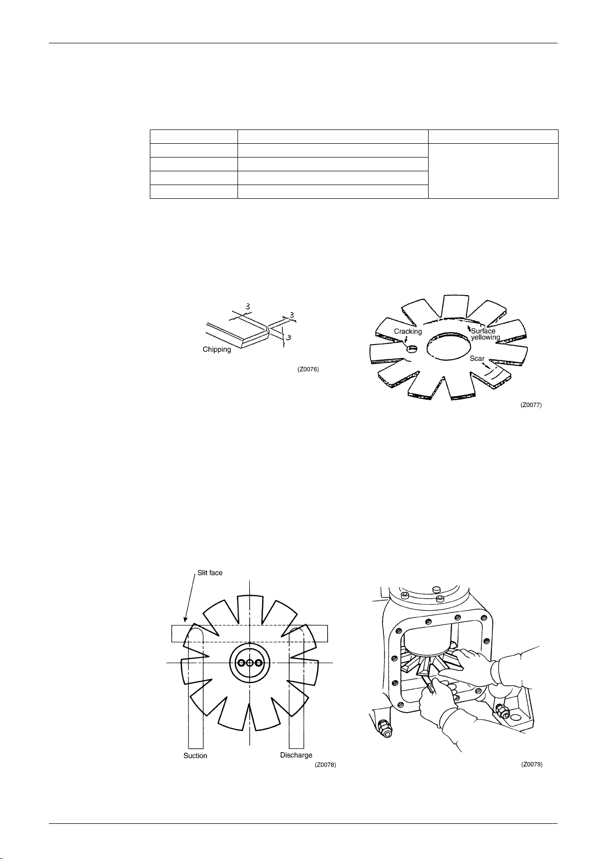
3. Inspecting The Gate Rotor
This inspection is done to check that no abnormal condition is present due to dust and other
foreign particles inside or harsh operating conditions of liquid compression, etc..
(1) Perform a pump down operation to reduce pressure inside the compressor.
(2) Release the internal pressure of the compressor.
Loosen the flare nut of the service port (with check valve) of the compressor (see Fig. 3-2).
Remove the partition lid, then tighten the flare nut to discharge refrigerant from the
compressor.
(3) Remove the side caps from both sides of the compressor. (Fig. 3-4)
Since a small amount of oil is still in the compressor, place drain pans under the side caps to
receive oil before opening the side caps.
Fig. 3-4 Side cap locations

Periodic Inspection Si50-203
8 Semi-Hermetic Single Screw Compressor Version III
(4) Inspection of the gate rotor
Visually check the gate rotor surface for scar, chipping, cracking, etc. Check all gate rotor
teeth.
Table 3-1 Gate rotor inspection standards
* When the yellowing is observed on the gate rotor blade, remove gate rotor and check the
damage on outside of the screw rotor.
If the damage on screw rotor is found, conduct one of the following counter measures.
- Repair (deburr, etc.) the damaged part of the screw rotor.
- Replace the screw rotor.
(5) Measuring the slit clearance
The slit clearance is a gap between the gate rotor and casing, and it affects the compressor
performance and reliability to a great extent. Therefore, the slit clearance must be set
properly (60 to 90 µm).
While pressing the periphery of the gate rotor shaft with fingers, insert a thickness gauge into
the slit clearance to measure the gaps on both suction and discharge sides. Be careful not
to insert the thickness gauge too deep. If the thickness gauge is inserted to deep, it can be
caught between the screw rotor and gate rotor and break.
(See Fig. 3-7 and 3-8.)
Item Standard Remedy
Cracking No cracking
Replace
Chipping No chipping 3 mm or more long in long side
Scar No scar 1 mm or more deep
Surface yellowing* No yellowing
Fig. 3-5 Inspection of gate rotor chipping Fig. 3-6 Inspection of gate rotor surface
Fig. 3-7 Slit clearance measuring location Fig. 3-8 Measuring slit clearance on suction side

Si50-203 Periodic Inspection
Semi-Hermetic Single Screw Compressor Version III 9
4. Cleaning The Suction Filter
(1) Perform a pump down operation to reduce pressure inside the compressor.
(2) Release the internal pressure of the compressor.
Loosen the flare nut of the service port (with check valve) of the compressor (see Fig. 3-2).
Remove the partition lid, then tighten the flare nut to discharge refrigerant from the
compressor. (Same as Section 3.2.2)
(3) Disconnect the suction pipe, and remove the suction filter.
(4) Remove dust and foreign particles from the inside of the filter by using compressed air and
cleaning solution. Check the filter thoroughly for tears and damage. (Replace the filter if
there is a tear.) Dry the filter thoroughly before installation to remove cleaning solution and
moisture.
Fig. 3-9 Suction filter location (Cross sectional diagram of casing)
Fig. 3-10 Cleaning suction filter

Overhaul Instructions Si50-203
10 Semi-Hermetic Single Screw Compressor Version III
4. Overhaul Instructions
The driving and friction parts in the compressor wear for prolonged over time. To prevent
accidents caused by worn parts, it is necessary to inspect those parts regularly and overhaul the
compressor as needed.

Si50-203 Overhaul Instructions
Semi-Hermetic Single Screw Compressor Version III 11
4.1 Disassembly and Inspection
1. Draining Oil
Drain oil by referring to Section 3.2.2 "Changing refrigerating oil."
2. Remove The Side Caps (One on Each Side) and The Discharge End Cover. (in case of
ZH9F, oil collector)
!Receive remaining oil with a drain pan.
!Be sure to mount guide bolts when removing the discharge end cover.
!Be careful not to damage the oil filter with the discharge end cover.
!Locate the first demister between the discharge end cover and cylinder cover, and remove it.
(Except ZH9F)
Fig. 4-1 Removing side cap Fig. 4-2 Removing discharge end cover
Fig. 4-3 Removing first demister

Overhaul Instructions Si50-203
12 Semi-Hermetic Single Screw Compressor Version III
3. Inspection of The Gate Rotor and Surrounding Parts
(1) Checking the slit clearance
Measure the slit clearance by referring to Section 3.2.3) "Inspecting The Gate Rotor."
(2) Measuring the backlash
Measure the backlash of the gate rotor and screw rotor. If the measured value exceed the
standard value, replace the gate rotor.
[Standard value] 0.15 mm or less for all teeth (ZH3, 5) and 0.20mm or less for all teeth
(ZH7, 9)
Fig. 4-4 Measurement of gate rotor backlash
4. Disassembling The Gate Rotor and Surrounding Parts
(1) Positioning the screw rotor
Position the screw rotor so that the gate rotor can be removed
without damage.
(2) Removing the gate rotor partition lid
In the ZH3F, the gate rotor partition lid is mounted together
with the lower bearing holder.
Fig. 4-5 Screw rotor position
Fig. 4-6 Cross sectional diagram of gate rotor

Si50-203 Overhaul Instructions
Semi-Hermetic Single Screw Compressor Version III 13
(3) Removing the gate rotor bearing retainer plate
While holding the gate rotor with hand, loosen the bolts. Be careful not to lose gate rotor
adjusting shims (1) mounted between the gate rotor shaft and retainer plate.
Be sure to use the original combination of gate rotor, lower bearing holder, gate rotor
adjusting shims and gate rotor adjusting shims (2). (Do not exchange parts between the
upper and lower sets).
Fig. 4-7 Removing gate rotor bearing retainer plate
(4) Removing the lower bearing holder (upward and downward units)
In the guide bolt hole, thread the bolt that was used for the lower bearing holder mounting
and lift the lower bearing holder from the casing.
Remove the shims inserted between the lower bearing holder and casing. (Do not lose
the shims.)
The lower bearing holder and casing are sealed by an O-ring. Therefore, it may be
difficult to remove the lower bearing from the casing. To separate them, insert two
standard screwdrivers at the flange section at locations opposite from each other, and
slowly twist the screwdrivers, as shown in Fig. 4-8.
Fig. 4-8 Removing lower bearing holder
In the upward gate rotor, the lower bearing holder falls off when the O-ring is separated.
Therefore, mount long bolts in the casing bolt holes and place a hand below the gate
rotor to support it during removal operation.

Overhaul Instructions Si50-203
14 Semi-Hermetic Single Screw Compressor Version III
(5) Turn the gate rotor shaft to remove it from the screw rotor. Be careful not to damage the
gate rotor.
5. Removing and Installation of Gate Rotor
(1) Remove C type retaining ring.
(2) Remove the gate rotor from the shaft.
(3) Apply red check to the gate rotor, and check that the rotor is free of cracks.
If the rotor is found cracked, replace it with a new one.
(4) Install the gate rotor on the shaft, and mount the C-type retaining ring.
The gate rotor has front and back sides. Position the gate rotor so that the manufacturing
number is visible.
6. Removing The Suction End Cover
(1) Remove all the mounting bolts.
(2) Mount guide bolts in two bolt holes on the upper section.
(Be sure to mount guide bolts, since the suction end cover is heavy.)
(3) In the guide bolt holes, thread the bolts that were removed previously, then remove the
suction cover from the casing.
Locate positioning pins at two locations, and screw them.
Fig. 4-9 Removing suction end cover

Si50-203 Overhaul Instructions
Semi-Hermetic Single Screw Compressor Version III 15
7. Removing The Motor Rotor
(1) Remove the rotor locking plate using a standard screwdriver.
(2) Loosen the lock nut. (Use the special tool or jig (1).)
(3) As shown in Fig. 4-11 grip rotor fins with pliers, and remove the rotor. Securely support the
rotor so as not to drop the rotor. At removal, be careful not to damage the stator coil end.
(4) Remove the motor rotor key from the screw shaft.
Fig. 4-10 Removing rotor locking plate
Fig. 4-11 Removing motor rotor

Overhaul Instructions Si50-203
16 Semi-Hermetic Single Screw Compressor Version III
8. Disassembly of The Controller
Fig. 4-12 Cross sectional diagram of controller
(1) Remove the slide valve arm.
Loosen the two locking nuts of the slide valve shaft and the bolt at the center of the arm.
A thread lock compound was used for the hexagon head bolt at the center. Use an impact
wrench to loosen this bolt.
Fig. 4-13 Removing slide valve arm

Si50-203 Overhaul Instructions
Semi-Hermetic Single Screw Compressor Version III 17
(2) Remove the oil filter using the special tool, and clean. (ZH3F only)
After cleaning, dry thoroughly.
If the filter is damaged or torn, replace.
Fig. 4-14 Oil filter removing tool
(3) Remove the mounting bolts, and remove the cylinder cover.
(4) Pull out the piston.
(5) Remove the mounting bolts, and remove the main bearing holder fixing plate.
Use guide bolts when removing the fixing plate, since it is heavy.
Do not lose screw adjusting shims (1) located inside.
(6) Remove the oil filter from the fixing plate, and clean. (except for ZH3F)
After cleaning, dry thoroughly.
If the filter is damaged or torn, replace.
(7) Remove the slide valve from the casing.
Fig. 4-15 Removing main bearing holder fixing plate

Overhaul Instructions Si50-203
18 Semi-Hermetic Single Screw Compressor Version III
9. Removing and Disassembling The Screw Assembly Pulley
(1) Place alignment marks on the casing and main bearing holder.
Fig. 4-16 Placing alignment marks on casing and main bearing holder
(2) Removing the screw shaft
Push the screw shaft from the suction side until the bearing holder completely extends from
the discharge side. Then pull out the shaft from the discharge side. Insert one hand through
the side cap hole and support the shaft to prevent the screw shaft from damaging the casing
when the screw rotor section comes out of the casing. Use leather gloves during removal to
prevent injuries by the screw and stator.
Fig. 4-17 Removing screw shaft (1)

Si50-203 Overhaul Instructions
Semi-Hermetic Single Screw Compressor Version III 19
Fig. 4-18 Removing screw shaft (2)
(3) Disassembling the screw assembly
Remove the bolts, and remove the screw bearing retainer plate.
Remove the main bearing holder from the screw shaft. Do not lose screw rotor adjusting
shims (2).
Fig. 4-19 Disassembling screw assembly
This manual suits for next models
20
Table of contents
Other Daikin Air Compressor manuals
Popular Air Compressor manuals by other brands

Draper
Draper DA270 instructions

Sparmax
Sparmax TC-620X user manual

Gude
Gude AIRPOWER 150/8/24 SILENT Translation of the original instructions

Streetwize
Streetwize S8AC14 quick start guide

Campbell Hausfeld
Campbell Hausfeld DP4615 operating instructions

Quincy Compressor
Quincy Compressor Industrial Series instruction manual