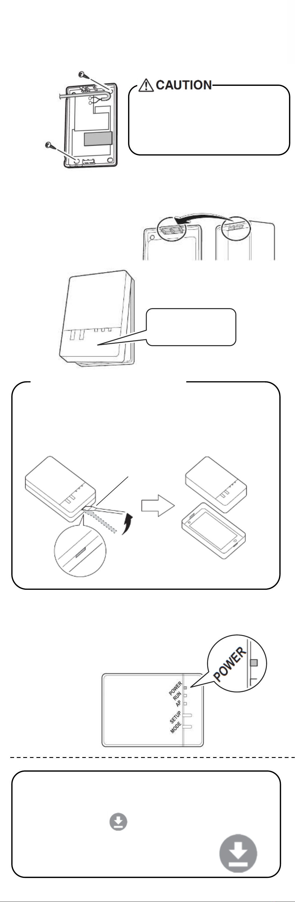
➍Return the adapter case to its original state.
➎Turn on the power supply, wait until the initial-
ization is completed. Check that the
[POWER] lamp for the product lights.
Configuration Connection
Settings Section
Troubleshooting
The following table provides brief descriptions of how to handle trouble or uncertainties when you install the product or make
connection settings.
See the homepage for details.
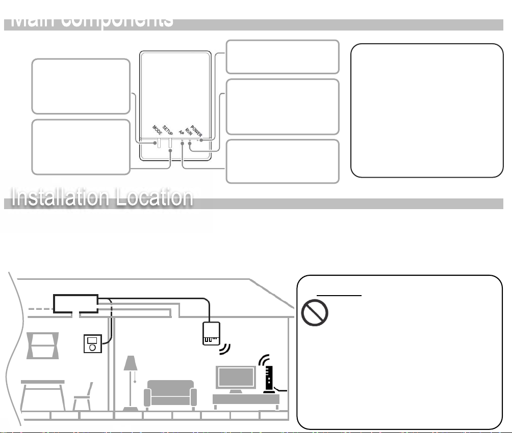
None of the lamps light. → Check the installation.
The product is behaving incorrectly.
→ Turn off the air conditioner power and restart it.
If you cannot connect a
touch controller to a
system (air conditioner),
the product is not installed
correctly.
Product lamp is extinguished.
→ Check that the RUN lamp is lit.
→ Check that the power is on.
→ Check the configuration and adapter settings again.
→ Check the physical LAN connection again.
→ There is a possibility that the router you are using may
not be supported.
See the homepage for details
When this happens Explanation and where to check
DAIKIN AUSTRALIA PTY. LIMITED
Sydney Office
62-66 Governor Macquarie Drive,
Chipping Norton NSW 2170 Australia
http://www.daikin.com.au 3P531285-1B
Snap the top of the upper
case unto the clip at the
top of the lower case and
press to close the box.
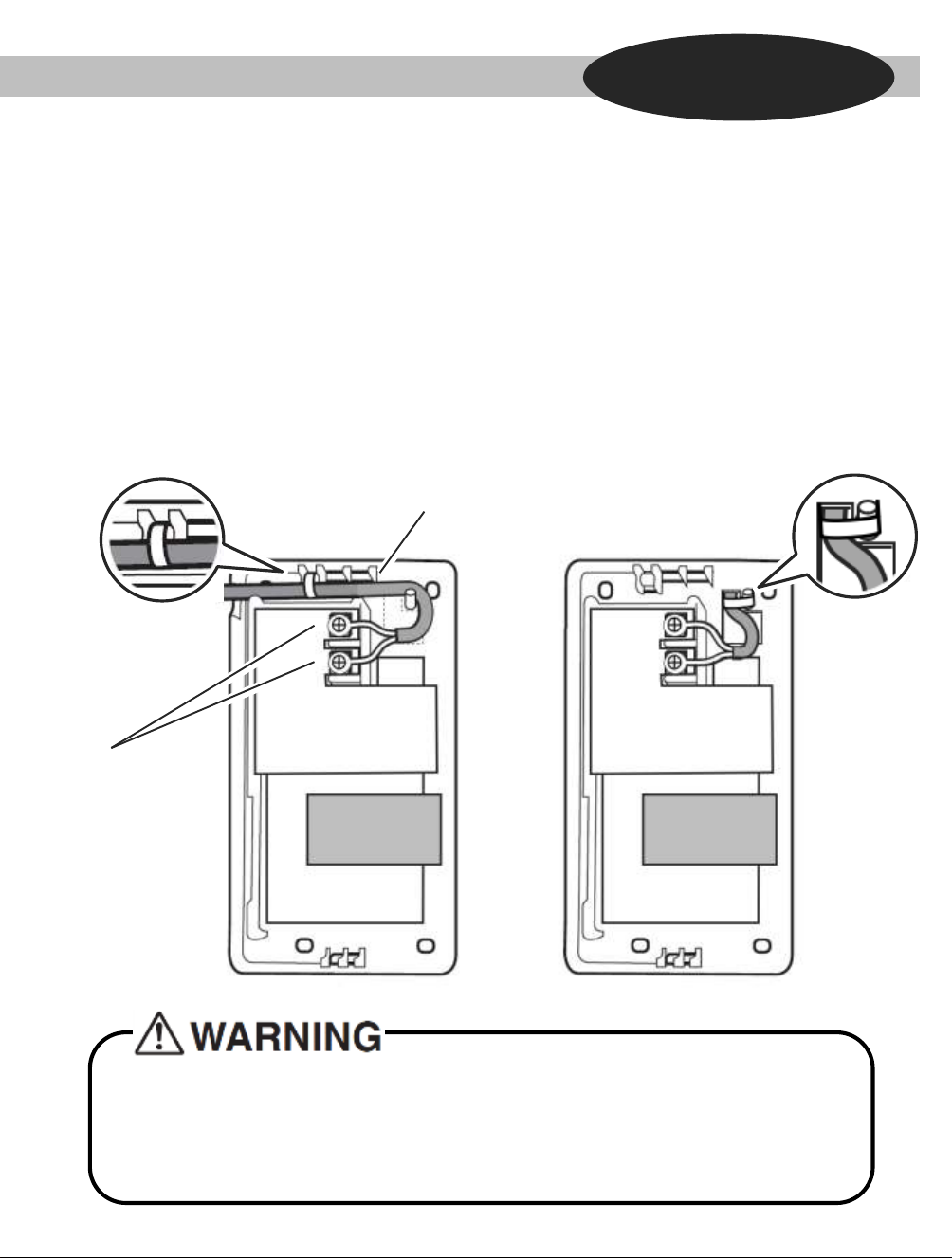
➌Attach the Adapter case.
ⒼMounting
screw
Using ⒼMounting screw or ⒺFastening tape, fix the
Adapter case on a wall.
When attaching Ⓓfastening seal,
there is a possibility of damaging the
wall, and adapter failing.
(Depending on the type of the wall,)
Press a minus screwdriver into the dent between the
upper and lower case to remove.
(Be careful not to damage the case)
When remove the adapter case
Upper Case
Lower Case
Minus
Screwdriver
➊Check that the [RUN] lamp is blinking.
• If [AP] is blinking or lit, hold down the
[MODE] button on the adapter for about 2
seconds to prompt the [RUN] lamp to begin
blinking.
➋Press the [WPS] button on the router
(wireless LAN access point).
• Operation procedures for the [WPS] button
vary by router (wireless LAN access point).
For details, refer to the instruction manual
for the router.
➌Hold down the [SETUP] button on the adapter for about 2
seconds.
• The [RUN] lamp will begin to blink more rapidly, and will change
to a continuous light once a
connection between the router (wireless LAN access point) and
the adapter has been
established.
If a connection fails to establish, repeat procedures from step 1 of
“Simple setup”.
➍Connect the smartphone (tablet PC) and the router (wireless
LAN access point).
• A connection can be established by opening the smartphone's
Wi-Fi network list, selecting the [SSID] for the router and entering
its password.
➎Tap the installed app [Airbase] to start it.
• If the connected air conditioner is listed in the units overview
screen, setup is complete.
If it is not listed, tap (refresh) in the top right corner of the units
overview screen.
The customer is responsible for providing the following.
• Smartphone or tablet PC
(Supported OS: Android 5.0 or later; iOS 8.0 or later.)
• Internet line and communicating device
(Modem/router or a similar device)
• Wireless LAN access point
• Mobile App [Daikin Airbase] (No Cost)
For Android Phones/Tablets
(1) Open the [Google Play].
(2) Search for [Daikin Airbase].
(3) Follow the directions on the
screen to install.
For iPhones/iPads
(1) Open the [App Store].
(2) Search for [Daikin Airbase].
(3) Follow the directions on
the screen to install.
[MODE] button
Simple Settings
Check whether the router to be used supports WPS.
• If WPS is supported ⇒Proceed to
• If WPS is not supported ⇒Proceed to
Simple Settings
Advanced Setting
Advanced Settings • All steps are demonstrated using iOS.
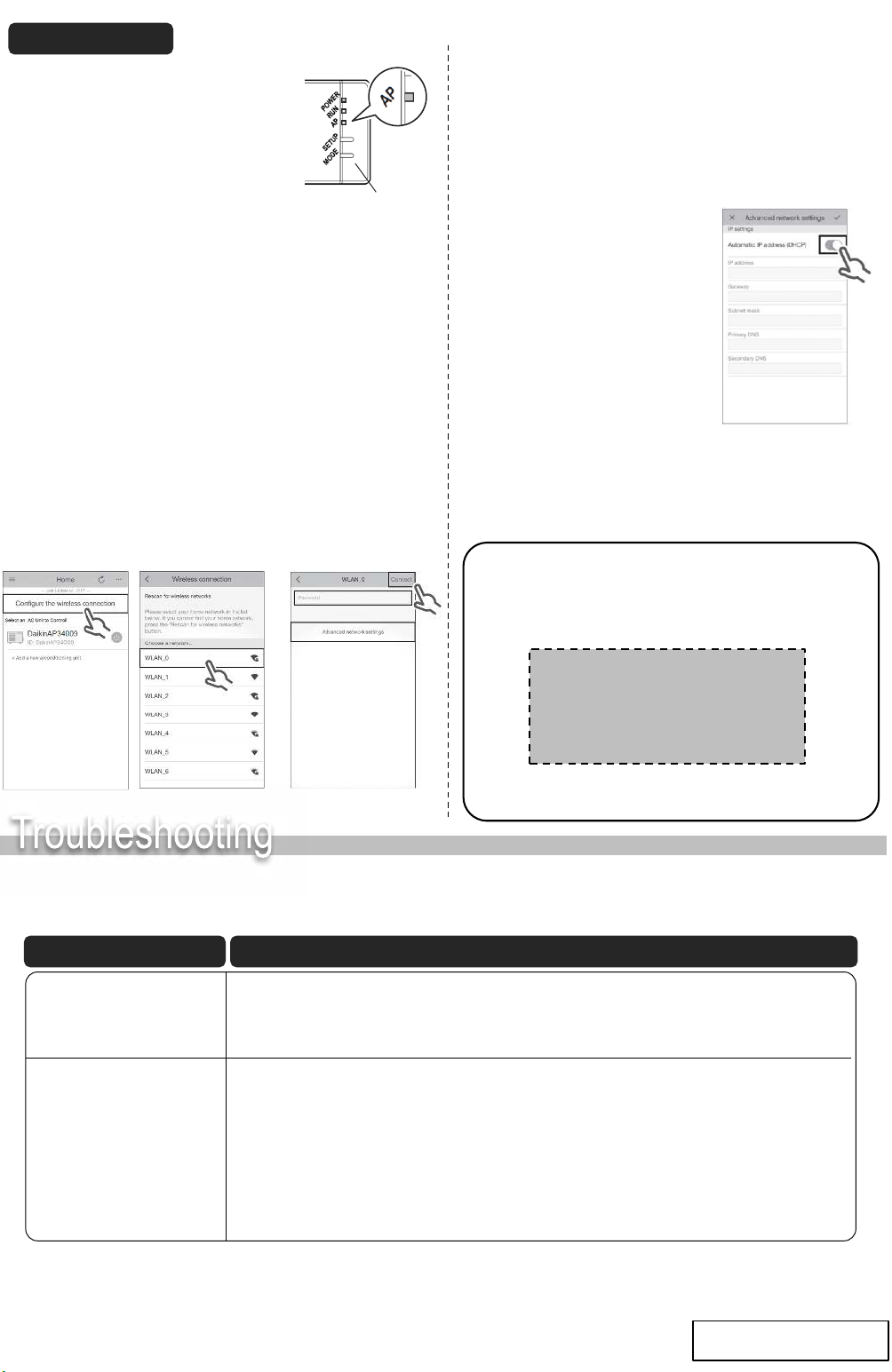
➊Check that the [AP] lamp is lit
(continuously).
• If the [AP] lamp is not lit, hold down the
[MODE] button on the adapter for about
two seconds to prompt the [AP] lamp to
light up (continuously).
(Lights in about 10 seconds.)
➋Connect the smartphone (tablet PC) directly with the
adapter via wireless LAN.
• Open the smartphone‘s Wi-Fi network list, select the [SSID]
(DaikinAP *****) shown on the serial number sticker Ⓑ, or the
wireless LAN connection adapter Ⓐ, and then enter the [KEY].
➌Tap the installed app [Airbase] to start it.
➍Make the wireless connection settings.
[MODE] button
When this happens Explain and where to check
⑴Tap [Configure
the wireless
connection].
⑵Select your home
Network from the
List.
⑶
➊Enter the password.
➋Tap [Connect].
➊
➋
★
(4) Follow the on-screen instructions from here onward to complete setup.
(5) After implementing the setting above and the product and router
(wireless LAN access point) are connected, the [RUN] lamp will light.
If this blinks for 1 minute or longer, check the power to the router
(wireless LAN access point), network name and the password and start
again from the first procedure.
To set the wireless connection
manually, tap [Advanced network
settings], turn off [Automatic IP
address (DHCP)], fill in the required
information for the Wi-Fi router, tap
[✔] and then tap [Connect] on the
wireless connection screen. Follow
the on-screen instructions and then
continue as in step (5).
★
➎Connect the smartphone (tablet PC) and the router
(wireless LAN access point), and then start [Airbase].
• Refer to step 4 and step 5 of “Simple setup”.
[About the SSID and KEY]
• The [SSID] and [KEY] shown on the Ⓒserial number
sticker are necessary when connecting the air conditioner
and a smartphone via wireless LAN.
Attach the Ⓒserial number sticker to the sticker
attachment area and keep safe.
[Sticker attachment area]
Push down until
you hear a click
Push down until
you hear a click
[Note]
• If an upgrade is available for your adapter, the
notification icon “ ” will be displayed on the
units overview screen.
Tap it to upgrade your firmware.
Installation method of Online controller