192
GB
Contents
1. Introduction ...................................... 193
1.1 Description ................................... 193
1.2 Operator interface ........................ 194
1.3 Receiver-compatible products..... 195
2. Preparation ....................................... 196
2.1 Tooling required............................ 196
2.2 Opening the receiver.................... 196
2.3 Choosing the best place
to install the receiver..................... 196
2.4 Fixing the receiver in place........... 197
3. Installation ........................................ 198
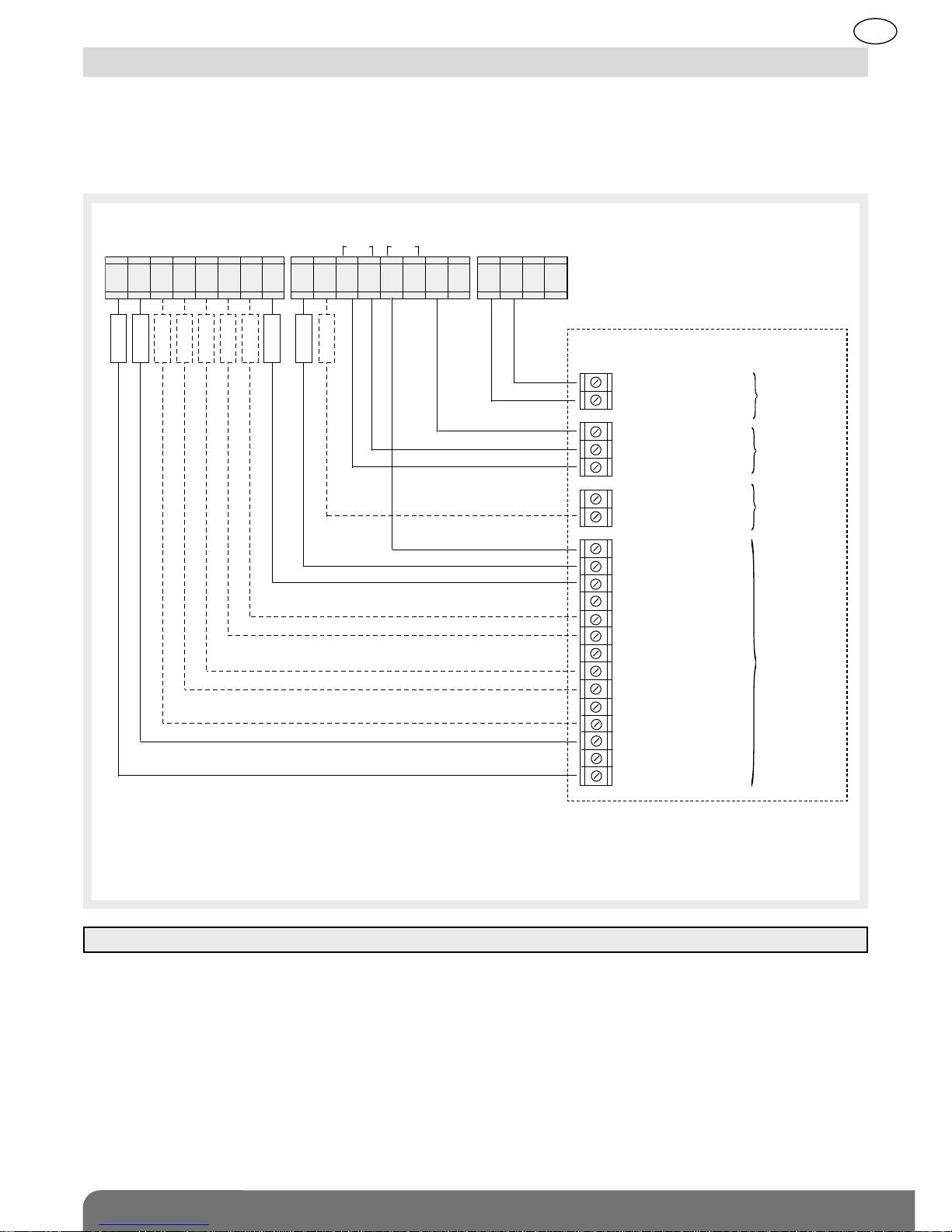
3.1 Connections for hardwired
inputs/outputs .............................. 198
3.2 Connection example .................... 199
3.3 Dip switches for selecting
parameters.................................... 200
3.4 Accessing the installation menu .. 200
4. Product recognition programming 202
4.1 Programming the detectors ......... 202
4.2 Programming the control
devices.......................................... 205
4.3 Checking recognition
programming ................................ 206
5. Programming.................................... 207
5.1 Table of main factory-
programmed functions................. 207
5.2 Operating modes for intrusion
output relays (Z1 to Z8) ................ 207
5.3 Changing intrusion output relay
operation (Z1 to Z8)...................... 210
5.4 Operating modes for tamper
relays (TMP).................................. 211
5.5 Changing tamper relay
operation....................................... 211
5.6 Operating modes for fault
output relay (FLT).......................... 212
5.7 Changing fault output relay
operation....................................... 213
5.8 Operating modes for control
panel arm/disarm relay (RAC) ...... 214
5.9 Changing control panel arm/
disarm relay operation.................. 214
5.10 Operating modes for arm/
disarm input (ARS)...................... 215
5.11 Changing arm/disarm input
(ARS) operation .......................... 216
6. Erasing .............................................. 217
6.1 Erasing programmed detectors... 217
6.2 Erasing all programmed
detectors....................................... 217
6.3 Erasing programmed control
devices.......................................... 218
6.4 Erasing all programming
(return to factory configuration).... 219
7. Checking the installation:
test mode.......................................... 220
8. Use..................................................... 221
8.1 Consultation menu ....................... 221
8.2 Intrusion alarm display mode....... 222
8.3 Tamper alarm display mode......... 223
8.4 Fault display mode....................... 224
8.5 Consulting the list of events......... 225
9. Installation sheet (pullout) .............. 227
10. Technical data ................................ 229
Recommendations
The user must not attempt to access the siren’s internal parts, except areas described in this
manual. If the user does access these parts, the product guarantee will be considered null and
void and DAITEM shall not be held responsible for any problems. Touching the siren’s internal
parts and/or electronic components can damage the product. Furthermore, the siren is designed
in such a way that these parts and components do not need to be accessed for operation or
maintenance purposes.
IMPORTANT: installers should install the receiver according to the instructions provided in this
manual and in compliance with applicable standards. They are responsible for any problems
arising from lack of compliance with these instructions and applicable standards.