DAITEM SH710AX User manual

Upgraded for e-Nova applications

GB
138
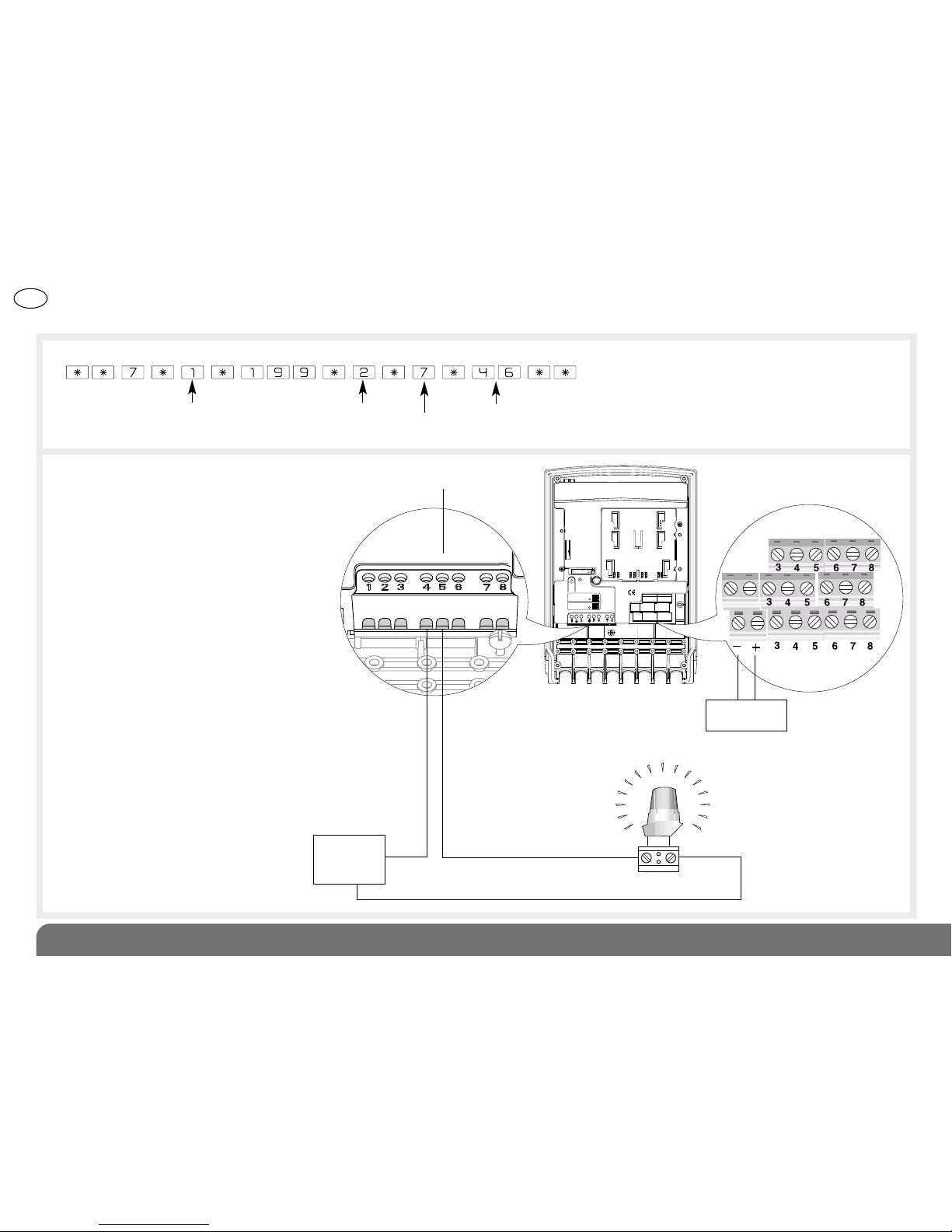
The SH710AX 8-channel relay output receiver acts as a control
and interface unit between the Daitem alarm system and other
electrical devices.
It is fitted with:
• an MPU01X lithium battery pack,
• a programming button and ED,
• a 12 V external power supply terminal block,
• a terminal block for the anti-tamper loop protecting the cable
linking the receiver and the device,
• 8 voltage-free outputs with anti-tamper protection.
Contents
1. Introduction ......................................................................................... 138
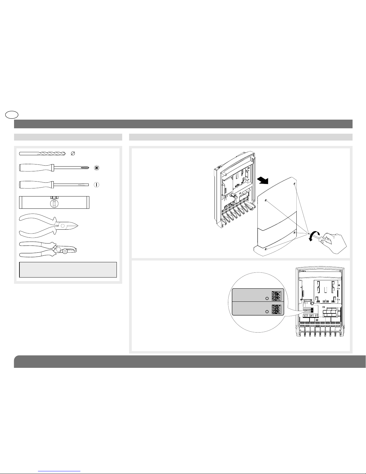
2. Preparation .......................................................................................... 140
2.1 Tooling required............................................................................... 140
2.2 Power supply .................................................................................. 140
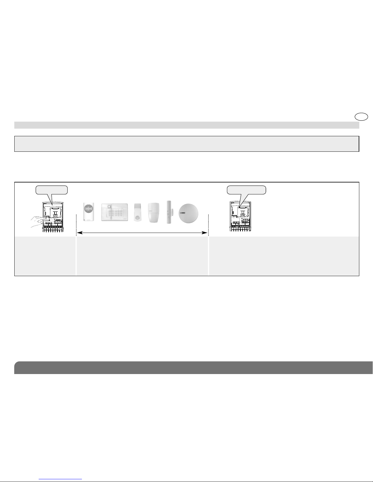
3. Recognition programming................................................................. 142
3.1 Programming the receiver to be recognised by the control panel 142
3.2 Programming a product to be recognised by the receiver............ 143
4. Parameter-setting............................................................................... 144
4.1 Setting the parameters of a receiver recognised
by a control panel ........................................................................... 144
4.2 Setting the parameters of a receiver recognised
by another product ......................................................................... 149
4.3 Operating mode change indication................................................ 151
4.4 Radio link validation in installation mode ....................................... 152
4.5 Receiver activation when the PSTN line or GSM
connection is cut............................................................................. 152
4.6 Radio anti-tamper protection ......................................................... 152
4.7 Deactivating the anti-tamper protection against removal ............. 152
4.8 Deleting parameter-setting ............................................................. 153
5. Installing the receiver ......................................................................... 153
5.1 Choosing the best place to install the receiver.............................. 153
5.2 Testing the radio range ................................................................... 153
5.3 Fixing the device in place ............................................................... 155
6. Switching to user mode ..................................................................... 159
7. Performing a real test......................................................................... 159
8. Maintenance........................................................................................ 160
8.1 Fault indications.............................................................................. 160
8.2 Changing the battery ...................................................................... 160
9. DAITEM guarantee and extension conditions ................................ 162
10. Technical data ................................................................................... 163
1. I troductio
Recommendations
• The device must be installed according to the applicable standards in the country and by an installer certified for electrical work.
• Before performing any maintenance on the product, disconnect the 220 V mains supply and the 12 V external power supply.
• The device’s internal parts must not be accessed, except areas described in this manual. If they are, the product guarantee will be considered null and void
and the user will not be able to make any sort of claim. Touching the device’s electronic parts and/or components can damage the product. Furthermore, the
device is designed in such a way that these parts and components do not need to be accessed for operation or maintenance purposes.
Description of symbols
The product complies with basic requirements for safety, health
and environmental protection.
Electrical
shock hazard Electrical shock hazard
Li
To prevent damage to the environment or adverse health effects,
you must not dispose of this product with household waste.
Please do not throw it away in an ordinary waste bin. It must be
taken to an appropriate collection point for waste treatment,
management or recycling. ithium battery packs contain
substances that may pollute the environment. They must
therefore be taken to a certified collection point.
The power supply used must bear this double insulation symbol.
230 V power supply without earth connection.

GB
139
Collersur certif
SH710AX
A1250A04823
SH710AX
A1250A04823
Test button ED
Anti-tamper loop connection
terminal block (loop enabled
only if wired on power-up)
Earthing connection terminal
block (terminals 7 and 8)
IMPORTANT: the two
terminals are connected
12 V DC external power supply terminal block
NO C NC NO C NC
Output 1
(terminals 1,
2 and 3)
Output 2
(terminals 4,
5 and 6)
2 high power outputs
• toggle switch
• ON/OFF mode
• 1.3 s pulse mode
• 2.5 s pulse mode
• timer for 5 durations:
- 10 s
- 90 s
- 3 min
- 15 min
- 30 min
Outputs 3 to 8
6 low power outputs
• toggle switch
• ON/OFF mode
• 1.3 s pulse mode
• 2.5 s pulse mode
• timer for 5 durations:
- 10 s
- 90 s
- 3 min
- 15 min
- 30 min
{
{
{
{
{
{
NO
C
NC
It is controlled:
• by the control panel if an alarm is triggered in order to activate various deterrents
and additional alerts (lighting, smoke generation, etc.),
• by other products directly (remote control units, keypads, pendants or detectors).
Refer to chapters:
• 3.1 Programming the receiver to be recognised
by the control panel
• 4.1 Setting the parameters of a receiver recognised
by a control panel
)))))
Refer to chapters:
• 3.2 Programming a product
to be recognised by the receiver
• 4.2 Setting the parameters
of a receiver recognised by
another product
)))))
AND/OR

GB
140
2. Preparatio
2.1 Tooling required 2.2 Power supply
IMPORTANT: the fixing screws and
plugs are not supplied.
8 mm
PZ 2
3.5 mm
1. oosen the 4 cover screws
and open the receiver.
Collersur certif
SH710AX
A1250A04823
SH710AX
A1250A04823
Coller sur certif
SH710AX
A1250A04823
SH710AX
A1250A04823
2. Remove the pre-cut part of the
sticker and stick it to the
guarantee certificate in the user
manual supplied with the control
panel. If you are adding to an
existing system, use the
guarantee sticker provided with
this product.

GB
141
3. Two types of power supply are possible.
• ithium battery pack
Connect the lithium
pack to its base. The
receiver beeps and
the ED lights up
green for 2 s.
• Power supply
Connect a 12 V DC
power supply
(10 V DC min/
15 V DC max) to
terminal blocks 1
and 2. The receiver
beeps and the ED
lights up green
for 2 s.
SH710AX
A1250A04823
3.5
SH710AX
A1250A04823
Trans-
former
12 V DC output230 V input
Cable length and cross-section
0 to 25 m fi0.75 mm2
Cable length and cross-section
0 to 10 m fi0.32 mm2
10 to 25 m fi0.75 mm2
IMPORTANT: the ED flashes red every 2 s. if
the magnet-based anti-removal system has not
been properly installed (see chapter 5.3 Fixing
the device in place).
Electrical shock hazard
OR
IMPORTANT
• The power supply used must bear the double insulation symbol (230 V power supply without earthing connection), 12 V/10 VA min.
• The power supply must be protected upstream by a circuit that can be isolated by a 16 A device.
• Make sure the battery is connected the right way round.
• Do not connect the external DC power supply at the same time as the lithium battery pack.
• Do not insert another source of power (power supplys, etc.) in the receiver box other than the power supplies intended; electrical disturbance and
power supply overheating can lead to receiver malfunctioning.

GB
142
3. Recog itio programmi g
IMPORTANT
• During recognition programming, the product to be programmed for recognition does not need to be close to the control panel. In fact,
it is advisable to move it at least 2 metres away.
• The control panel issues three short beeps to indicate an error, the receiver issues three short beeps to indicate a programming error
and the green ED flashes. When this happens, perform recognition programming again from the start.
• The receiver and control panel must be in installation mode. The receiver is in installation mode when powered. Refer to the installation
manual for the control panel.
Briefly press the receiver
“test” button
Press and hold the
“Off” button on the
control panel until the
panel responds
10 s max.
“beep, device X”
)))))
SH710AX
A1250A04823
)))))
“beep” “beeep”
The control panel issues
a voice message to
indicate the receiver n°
The receiver issues a
beep to validate
recognition programming
“beep, disarmed,
con rol panel”
Open the control panel cover and proceed as follows:
Next refer to chapter 4.1 Setting the parameters of a receiver recognised by a control panel.
3.1 Programming the receiver to be recognised by the control panel

GB
143
“beeep”
3.2 Programming a product to be recognised by a receiver
IMPORTANT: if you wish to use other products directly with the receiver as well as the alarm control panel, the receiver must first be
programmed for recognition by the control panel and then the products must be programmed for recognition.
Briefly press the receiver
“test” button
Press and hold:
• the “OFF” button on the remote control or keypad (in
installation mode)
• or the pushbutton on the pendant
• or the “Test” button on the detector
• or the 0 programming button on the smoke detector
until the receiver responds
10 s max.
SH710AX
A1250A04823
)))))
“beep”
The receiver issues
a beep to validate
recognition programming
A maximum of 16 products (remote controls, detectors, etc.) can be programmed for direct recognition by the receiver.
The channel and operating mode must then be allocated to the output concerned (see 4.2 Setting the parameters of a
receiver recognised by another product).

GB
144
4. Parameter-setti g
4.1 Setting the parameters of a receiver recognised by a control panel
IMPORTANT
• Before setting the receiver’s parameters, recognition programming must first be performed (see 3.1 Programming a receiver to be
recognised by the control panel).
• All parameter-setting must be performed using Twin oad®software available in the Daitem installers section at www.daitem.co.uk.
Output Description
Contact in rest position
Operation
1
Disarming (NC)
and Total Arming
(NO):
On/Off mode NO CNC
NC-C contact closes
when Disarming signal
received from control
panel
NO-C contact closes
when Arming signal
received from control
panel
2ight control:
On/Off mode
NO CNC
NO-C contact closes when
ight On channel received
and NC-C contact closes
when ight Off channel
received.
3
Anti-tamper:
NO/NC 1.3 s
pulse mode (1)
NO
C
NC
NO-C contact closes
when anti-tamper
signal received
from control panel
4
Single or
confirmed
intrusion:
NO/NC 1.3 s
pulse mode
NO
C
NC
NO-C contact closes
when single or confirmed
intrusion signal received
from control panel
Output Description
Contact in rest position
Operation
5
Fire alarm:
NO/NC 1.3 s
pulse mode
NO
C
NC
NO-C contact closes
when Fire signal
received from control
panel
6
Technical
alarms:
NO/NC 1.3 s
pulse mode
NO
C
NC
NO-C contact closes
when Technical alarm
signal received from
control panel
7
Individual
protection:
NO/NC 1.3 s
pulse mode
NO
C
NC
NO-C contact closes
when alert or silent alarm
signal received from
control panel
8
Power fault:
NO/NC 1.3 s
pulse mode (2)
NO
C
NC
NO-C contact closes
when power fault signal
received from control
panel
(1) Activation of system device anti-tamper protection against opening
and/or removal of receiver box or break in receiver anti-tamper loop.
(2) • Power fault in system device or control panel: NO/NC 1.3 s pulse mode.
• Power faul of receiver external power supply: NO-C contact closes.
When the receiver has been programmed for recognition by a control panel, the outputs are factory programmed to operate as
follows:

GB
145
If this configuration is suitable, the operating modes of the different outputs do not need to be programmed. If not, the channel and
operating mode associated with each output are allocated using the control panel keypad according to the procedure below:
output n°
(from 1 to 8)
receiver n° channel value (see table below)
Operating mode
• 1: disabled
• 2: On/Off
• 3: toggle switch
• 4: 1.3 s pulse mode (1)
• 5: 2.5 s pulse mode (2)
• 6: 10 s timer
• 7: 90 s timer
• 8: 3 min timer
• 9: 15 min timer
• 10: 30 min timer
(1) For operating the Daitem gate control system
of an automatic or semi-automatic gate
(opening of one side only).
(2) For operating the Daitem gate control system
of an automatic or semi-automatic gate
(opening of both sides).
Channel Value
Warning 1
Deterrence 2
Prealarm 3
Single or confirmed intrusion (all groups) 4
Single or confirmed intrusion group 1 5
Single or confirmed intrusion group 2 6
Single or confirmed intrusion group 3 7
Single or confirmed intrusion group 4 8
Single or confirmed intrusion group 5 9
Single or confirmed intrusion group 6 10
Single or confirmed intrusion group 7 11
Single or confirmed intrusion group 8 12
Alert 13
Silent alarm 14
Fire alarm 16
GSM or PSTN telephone line anti-tamper 17
“Protection active” indication 18
ight On/Off 19
Channel Value
ight toggle switch 20
ight timer 21
Relay 1 Off/relay 1 On 22
Relay 1 toggle switch 23
Relay 1 timer 24
Relay 2 Off/relay 2 On 25
Relay 2 toggle switch 26
Relay 2 timer 27
Relay 3 Off/relay 3 On 28
Relay 3 toggle switch 29
Relay 3 timer 30
Relay 4 Off/relay 4 On 31
Relay 4 toggle switch 32
Relay 4 timer 33
Disarm/Arm 34
Disarm/Partially arm 1 35
Disarm/Partially arm 2 36
Disarm/Arm group 1 37
Disarm/Arm group 2 38
Channel Value
Disarm/Arm group 3 39
Disarm/Arm group 4 40
Disarm/Arm group 5 41
Disarm/Arm group 6 42
Disarm/Arm group 7 43
Disarm/Arm group 8 44
Disarm/Arm all groups 45
All alarms/”Protection active” indication 46
Technical alarms 47
Individual protection (alert, silent alarm) 48
Self-monitoring (mechanical, radio, GSM
or PSTN line anti-tamper) 49
Power fault 50
Anti-tamper protection
(against cover opening, anti-tamper loop
or power supply cut) 51
Single intrusion (all groups) 52
Confirmed intrusion (all groups) 53

GB
146
Example: activating 220 V lighting for 90 s when an alarm is triggered
1. Proceed as follows using the control panel keypad:
2. Wire as shown:
Output used: 2
Timer: 90 s
receiver n° 1 All alarms channel
Collersur certif
SH710AX
A1250A04823
SH710AX
A1250A04823
Output 2
NO C NC NO C NC
230 V mains
supply with
protection
12 V DC
supply
{

GB
147
Example: activating a Bandit 240DB dense fog machine.
Continuous alarm system arming (output 1) information and confirmed intrusion (output 4) are required.
The SH710AX receiver is powered via the Bandit system.
1. Output 1 is factory programmed for Disarming/Total arming. If this is not the case, proceed as follows using the control panel
keypad:
Output used: 1 On/Off
receiver n° 1 Disarm/Arm channel
Then programme output 4 again using the control panel keypad:
Output used: 4 1.3 s
pulse mode
receiver n° 1 Confirmed intrusion channel
(all groups)

GB
148
Collersur certif
SH710AX
A1250A04823
SH710AX
A1250A04823
tuoKO
Grdout
Alout
OKout
Error
COM
Tmpout
Tmp
nidrG
ninaP 1nilA ylppuS
12 V
500 mA
aT +P +A G+
+
Tb
-P
-A G-
-
6.3AT
Led jaune d’échauffement
Bouton à
lire dips
Attention: zone palpable
d’alimentation
LEDs rouges:
12 V sur entrée.
Rouge
Blanc
Vert
Bleu
Orange
Noir
Connecteur à 5
points pour télécommande
Red jump
PaninV
GrdinV
F2
F3
ON ON
11
22
33
ON
1234
Bloc A
Bloc B
Bloc C
500mA
AlinV
daeR
npn
Bouton
Reset
teseR
npn
L
N
N
N
.
mirpofsnarT
.cesofsnarT
edW057ehcuotraC
l’ ruelahcedruegnahcé
.a.cV032
noitatnemilA
1.25AT
F1 4AT
F4
Output 1
NO C NC NO C NC
2. Wire as shown:
3. For programming the Bandit, refer to the system manual.
{
230 V mains
supply with
protection

GB
149
A maximum of 10 products of the same type (remote control, keypad, pendant or motion or door/window detector) can be
programmed for recognition on each output. The different products or control devices concerned must dispatch the same signal.
If several products have to be programmed for recognition on the same output, the parameter-setting procedure must be performed
for each product.
4.2 Setting the parameters of a receiver recognised by another product
To start the
procedure, press
and hold the
“test” button until
the ED goes out.
Press the “test”
button as many
times as is
required for the
selected output.
Output number
• output 1: press once
• output 2: press twice
• output 3: press 3 times
• output 4: press 4 times
• output 5: press 5 times
• output 6: press 6 times
• output 7: press 7 times
• output 8: press 8 times
Operating mode
• 1: disabled
• 2: On/Off
• 3: toggle switch
• 4: 1.3 s pulse mode (1)
• 5: 2.5 s pulse mode (2)
• 6: 10 s timer
• 7: 90 s timer
• 8: 3 min timer
• 9: 15 min timer
• 10: 30 min timer
IMPORTANT: before setting the receiver parameters, recognition programming must be performed (see 3.2 Programming a product to be
recognised by the receiver).
(1) For operating the Daitem gate control system of an automatic or semi-automatic gate (opening of one side only).
(2) For operating the Daitem gate control system of an automatic or semi-automatic gate (opening of both sides).
The receiver
issues a beep
to validate
parameter-
setting
“beeep”
Press and hold
the “test”
button until the
ED goes out.
Press the “test”
button as many
times as is
required for the
operating mode.
To end the
procedure, press
and hold the “test”
button until the
ED goes out.
)))))
• Move your hand in front of the infrared
detector lens or move the magnet away from
the door/window detector to trigger detection
• Or press and hold the button concerned on
the remote control or keypad (in installation
mode) or the pendant pushbutton.
• Or press and hold the test button on the
smoke detector
until the receiver responds
SH710AX
A1250A04823
SH710AX
A1250A04823
abou 10 s
SH710AX
A1250A04823
SH710AX
A1250A04823
SH710AX
A1250A04823
abou
5 s abou 10 s

GB
150
SH710AX
A1250A04823
SH710AX
A1250A04823
SH710AX
A1250A04823
SH710AX
A1250A04823
SH710AX
A1250A04823
To start the
procedure, press
and hold the “test”
button until the ED
goes out.
Press the “test”
button twice for
output 2.
Press and hold
the “test” button
until the ED
goes out.
Press the “test”
button twice for
On/Off mode.
To end the
procedure, press
and hold the “test”
button until the ED
goes out.
Press “OFF” on the
remote control until the
receiver issues a beep
to confirm.
Press “ON” on the
remote control until the
receiver issues a beep
to confirm.
Operation (1)
Press ON
on the remote control
Press OFF
on the remote control
device switched on device switched off
abou
5 s abou 10 sabou 10 s
Specific case: activating 220 V lighting using a remote control.
Output used: 2
On/Off mode
1. Proceed as follows:
(1) In this type of application, instead of pressing the alarm ON button to activate lighting, you can instead press a button specifically programmed for ight On,
Relay 1 On, Relay 2 On, etc.
Similarly, instead of pressing the OFF button to deactivate lighting, you can press a button programmed for ight Off, Relay 1 Off, Relay 2 Off, etc.
“beeep”
)))))
“beeep”
)))))

GB
151
Collersur certif
SH710AX
A1250A04823
SH710AX
A1250A04823
Output 2
NO C NC NO C NC
230 V mains
supply with
protection
12 V DC
supply
{
2. Wire as follows:
A beep can be issued to indicate each change in system operating status.
To activate or deactivate this feature, use the control panel keypad to enter the following:
4.3 Operating mode change indication
0: disabled
1: enabled (factory)
receiver n°

GB
152
This function is for validating the radio link test in installation mode on 1 of the 2 radio bands.
To switch to 2 radio bands, enter:
4.4 Radio link validation in installation mode
0: validation on 1 of the 2 bands (factory)
1: validation on the 2 bands
receiver n°
Commands are only taken into account if a PSTN line or GSM cut message has first been sent by the control panel or dialler.
The receiver is “deactivated” when the PSTN line or GSM connection is restored.
To enable or disable this function, use the control panel keypad to:
4.5 Receiver activation when the PSTN line or GSM connection is cut
0: disabled (factory)
1: enabled
receiver n°
The receiver monitors availability of the radio links. If these are purposefully tampered with, the receiver sends a radio tamper
message triggering the alerts and deterrents.
To modify radio anti-tamper triggering, use the control panel to enter:
4.6 Radio anti-tamper protection
0: disabled (factory)
1: enabled
receiver n°
If there is an attempt to remove the device, the receiver sends a tamper message triggering the alerts and deterrents.
To deactivate the anti-tamper protection against removal, use the control panel keypad to enter:
4.7 Deactivating the anti-tamper protection against removal
0: anti-tamper enabled (factory)
1: anti-tamper disabled
receiver n°

GB
153
4.8.1 Deleting the parameter settings of the receiver recognised by a control panel
The factory parameter settings of an output are restored using the control panel keypad.
With the control panel in installation mode, use the keypad to enter:
4.8 Deleting parameter-setting
output n° (from 1 to 8)
receiver n°
4.8.2 Overall deletionl
To return to factory parameter settings and delete all products recognised by the receiver:
1. disconnect the receiver power supply,
2. reconnect the power supply and press the test button at the same time, holding it down until a beep is issued (about 5 s),
3. release the button and a long beep is issued to confirm the receiver’s return to factory parameter settings.
The receiver can be installed:
• inside,
• outside but in a location sheltered from the weather,
• making sure there is a distance of at least 2 metres between each product, except between two detectors,
• at a height above 1 m from the ground and clear of any obstacles (furniture, metallic structures, etc.),
• far away from possible sources of electrical disturbance (electricity meter, telephone cabinet, etc.).
The receiver cannot be installed:
• directly on a metallic surface,
• too close to electrical devices generating interference: electricity meter, telephone cabinet, computer, etc.
5. I stalli g the receiver
5.1 Choosing the best place to install the receiver
Before fixing the receiver in place, position it in the intended location and then test the radio range.
If the tests are satisfactory, fix the receiver in place. If not, move it to a different location.
5.2 Testing the radio range

GB
154
5.2.1 Testing the receiver
1. Press the receiver
“test” button for more
than 5 s. The ED
lights up.
2. The control panel
issues the voice
message:
3. The receiver issues a
long beep to confirm.
SH710AX
A1250A04823
“beeep”
“beep, es ,
device X”
5.2.2 Testing other products
2. Check that the corresponding programmed
output responds to the receiver.
or
• or one of the buttons on the
remote control or keypad (in
installation mode) programmed
for recognition by the receiver,
• or the pendant pushbutton,
until the receiver responds.
or
or
1. Press and hold:
• the detector “test” button
“beep”

GB
155
1. oosen the locking screw
on the fixing bracket and
remove the bracket.
5.3 Fixing the device in place
2. Mark the 3 fixing points and drill the holes using an
appropriately sized drill bit.
Pozidriv 2
3. Remove the washer, insert it and fix the bracket in place using suitable
plugs and screws.
4. Take the anti-removal magnet drilling template
supplied in the bag of accessories and insert it
on to the fixing bracket.
Remove and
dispose of the
unused washer.

GB
156
5. In compliance with the following drilling
requirements, drill a hole for the anti-
removal magnet using a suitable 8 mm
diameter drill bit.
Hole: 8 mm Ø x 34 mm
7. Hook the base on to the fixing
bracket.
¿
¡
6. A. Remove the anti-removal magnet drilling template using a flat-headed screwdriver.
B. Take the magnet and the plug out of the bag of accessories.
C. Put the magnet in the plug.
D. Insert the plug into the hole drilled in step 5.
BD
C
A
3.5
Table of contents
Other DAITEM Receiver manuals