Daitron PFS300A-12 User manual

Prior to Use
・Please read this instruction manual carefully.
・Please use product only as directed or severe damage to the product may occur.
・Not properly following these guidelines may result in extremely hazardous conditions that could cause electrical shock or fire.
WARNING
・
Do not modify the product nor remove the protective enclosure. Under the protective enclosure are
contained high voltage and high temperature components during normal operation and after complete shutdown.
Avoid electric shock or burns by avoiding them.
・Under the protective enclosure are contained high voltage and high temperature components during normal operation and
after complete shutdown. Avoid electric shock or burns by avoiding them.
・Keep face and hands away at all times during operation to avoid unexpected injury.
・DANGER. Risk of fire, electric shock, and injury. DO NOT continually operate if there is smoke, odor, or irregular noise. Instead
immediately turn off the power and contact us. Do not attempt to repair it yourself because it is dangerous to do so.
・DANGER. Risk of fire, electric shock, and injury. DO NOT insert or drop any object in openings, this could cause unit failure or
severe hazardous conditions.
・DANGER. Risk of fire, electric shock, and injury. DO NOT use the product with condensation present, this could result in electric
shock or fire.
CAUTION
・This power supply is intended to be used as a component of a larger system of electrical equipment.
User is responsible for the safe design when this product is to be integrated in the equipment which requires
particularly high quality and reliability. There is a possibility to endanger persons or property by a failure or
malfunction of this product.
・Avoid sharp and sudden impacts to this unit such as dropping or damage will likely result.
・Ensure and maintain input voltage, output current, output power, ambient temperature, and humidity within specification or unit
may be damaged.
・Safety standards for this product are based on the condition that the product is to be used with forced air cooling. To prevent
the temperature of internal parts from exceeding the specification, ensure that the product is exposed to proper airflow when
installing
・Ensure that wires are properly secured to the input and output terminals as specified in this manual.
・Be sure to turn off the power before making the output connection.
・DO NOT use in a special environment (e.g. in the presence of strong electromagnetic field or erosive gas)
or environment where conductive foreign substance is present.
・DO NOT use or store product where condensation may occur due to moisture or humidity. For use in such conditions,
waterproof protection is necessary and must be installed.
・Do not operate under over current or short-circuit conditions for more than 10 seconds otherwise damage
and electrical insulation failure will likely result.
・No stress (e.g. twist, deflection) should be applied to the print board when the product is installed.
・Avoid impacts, such as dropping this product.
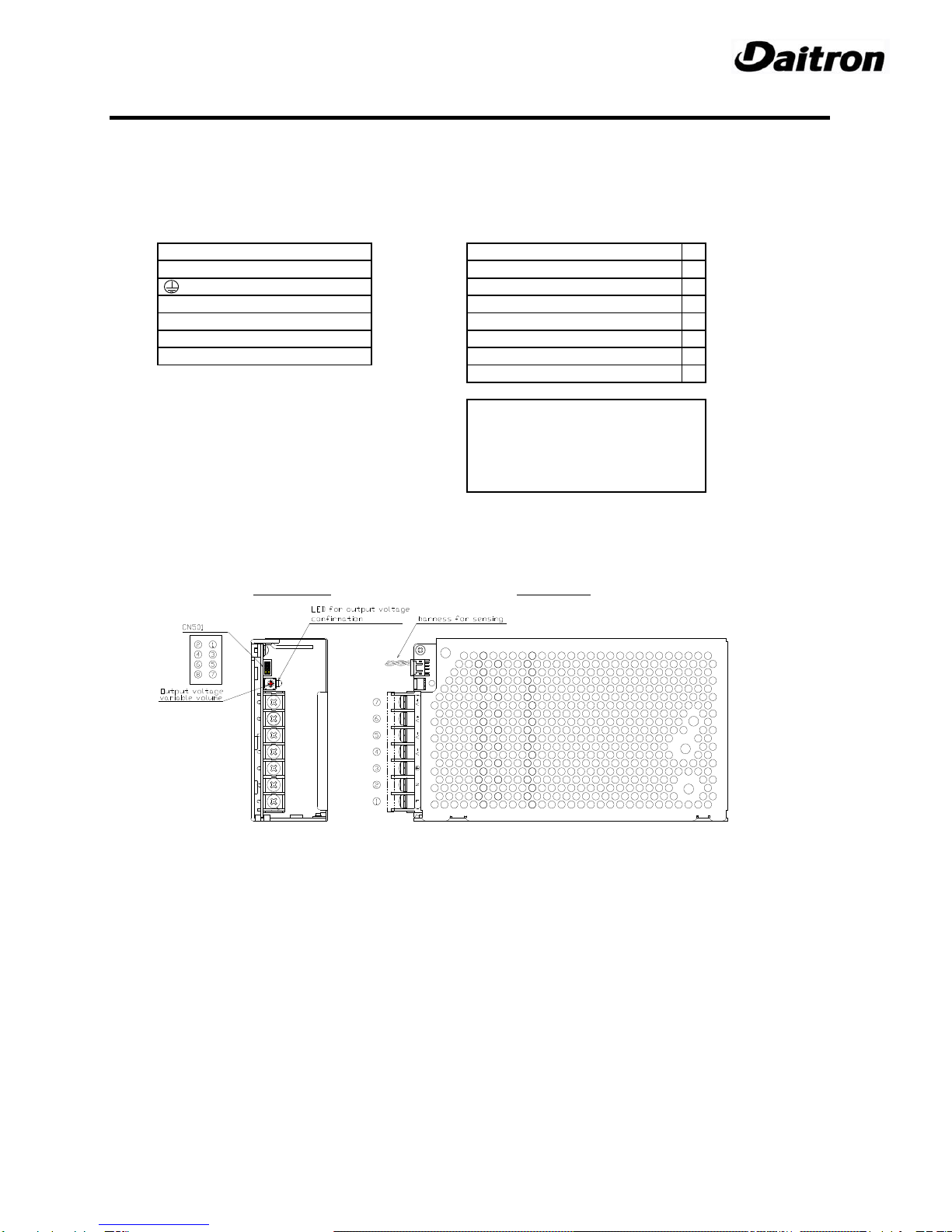
・Do not apply the load to signal connector CN501.
・DANGER. Output of this product is regarded as hazardous energy so this should not be accessible to end users.
・Use appropriate connecters for the terminal connection.
For the crimping of the contact, use the crimping tool recommended by the manufacturer.
・Prevent accidental contact with the output terminal of this product from dropped items such as tools by insuring proper
orientation and shielding/cover.
・Turn off the input power and ensure that the input and output terminal voltage drops to zero.
・This product uses fuses in the double pole/neutral line. When it is used for information processing equipment
(IEC/EN/UL60950-1), the following label must be provided for service engineers.
【CAUTION DOUBLE POLE / NEUTRAL FUSING 】
Special Instructions for IEC/EN/UL60601-1
CAUTION
・These products are not suitable for use in the presence of flammable anesthetic mixtures with oxygen or with nitrous oxide.
・These products have not been assessed to IEC/EN/UL60601-1-2(EMC), but EMC test data is available from us.
PFS300ASeries
Instruction Manual
UL60950-1, #E237238
UL60601-1, #E320635
RoHS Compliant
10001-005WE-00

1
.
Terminal Explanation
・Ensure AC power is off prior to connecting inputs and outputs.
・Connect FG terminal to earth terminal of device or equipment.
・Route AC and DC wires separately to minimize noise.
・Be sure to use each terminal (pole) of the terminal block at 20A or less.
●TERMINAL BLOCK (TB101) ●
Connector :CN501
L:AC Line +S :+ Output Remote Sensing ①
N
:AC Neutral +VS :+ Output Voltage Check ②
:Frame Ground -S :- Output Remote Sensing ③
-V : - Output terminal
-VS
:- Output Voltage Check
④
-V : - Output terminal : Not in use ⑤
+V : +Output terminal : Not in use ⑥
+V : +Output terminal +R :+Remote Control ON/OFF ⑦
-R :- Remote Control ON/OFF ⑧
CN502(not included)
Connector :S8B-PHDSS(JST)
Housing :PHDR-08VS
(Terminal) :SPHD-001T-P0.5
Crimping tool :AP-K2N
For proper connection to CN501 please assemble CN502 (not included)
using parts above
Front-View
Top - View
10001-005WE-00

2.機能説明
Function explanation
Input voltage Over-Voltage Protection(OVP)
・
AC input voltage range: 85-264VAC (47~63Hz)
・During an over voltage fault OVP circuitry will disable output
・To avoid damage, please use within recommended range until fault is removed and unit is allowed to reset.
・Once OVP is activated, output is continuously shut off as
long as the input power is supplied
・
Turn off power and ensure supplied voltage stays within
Output voltage setting tolerable limits (100-240VAC) and wait a few minutes before
powering up again.
・After reset output voltage might be abnormal, so it should be
・Adjust DC voltage output by using Output Adjustment confirmed and adjusted as needed.
Potentiometer located next to the CN501 connector.
・CW = increase, CCW = decrease.
・Use in the following range:
・Within the rated output voltage ±10% at the output terminal
(For PFS300A-5, it a variable range of 4.5 to 6V.)
・Slowly turn the potentiometer, not to exceed the rated voltage. ・During an over temperature fault OTP circuitry will disable
output until fault is removed and unit is allowed to reset
・Turn off power and allow unit to cool by wait a few minutes
Inrush Current before powering up again.
・Confirm the forced air convection allows for cooling airflow.
・This unit comes with an integral inrush current limiting Remote Sensing
circuit using a power thermistor.
・Since SCR is used to prevent inrush current, the inrush
current limiting circuit may have been released if the ・The remote sensing function is built-in.
power is turned on again in a short time. Be sure to wait ・Please note that the maximum allowable voltage drop
enough time before powering up again. from Load to CN terminal is 0.3V.
・Please twisted pair wires installed in parallel with load
・Proper selection of component providing power (contactor, wire as shown below.
fuse, circuit breaker, etc…) to this unit requires ratings
compatible with AC IN 100V : 20A / ACIN 200V
: 40A (Ta=25℃Cold Start)
due to internal SCR circuitry.
Over-current Protection(OCP)
・
When it exceeds 110% of the rated output current,
OCP shuts off the output.
・Turn off power and remove fault and wait a few minutes
before powering up again.
・Avoid operation in the over current state longer than 10
If no Remote Sensing will be used, please retain CN501 jumper
seconds or damage to the power supply may occur.
connector as shown:
Over Temperature Protection (OTP)
・Do not exceed the maximum output power and rated output current.
2-2
2-5
2-6
2-3
2-1
2-4
2-7
10001-005WE-00

Remote On/Off Parallel Operation
・This unit comes with an integral on/off circuit, see wiring ・This power supply can not be configured in parallel with
diagram below. another power supply.
・Unit DC output is disabled when control voltage is applied
to RC terminal in reference to –V terminal.
・If SW is open or control voltage E is: 0 < E < 4.5V then unit
output is enabled.
・If SW is closed and control voltage E is: 4.5VDC < E
< 6.5VDC then output is disabled, and no need for current
limiting resistor R.
・If SW is closed and control voltage E is: 6.5VDC < E
< 24.5VDC, then current limiting resistor R must be =
(E – (1.1 +1000x0.005))/0.005. For example if E = 24VDC,
R = (24-(1.1+5))/0.005 = 3.5kΩ
Ripple
・Maximum ripple voltage is measured using JEITA
measurement method prescribed in RC-9131C.
・If ripple noise becomes excessive due to line length,
connect an electrolytic capacitor(47μF) and film capacitor
(0.1μF) at load side as shown.
Series Operation
・This Daitron power supply unit is configurable in series
with another Daitron power supply (if it too is configurable
in Series) in order to increase DC voltage or to provide
both “+” and “–“ DC voltage.
・In these configurations the MAXIMUM current delivered to
the Load is limited to the maximum allowable from the
power supply with the lowest current rating.
・To increase VDC (PS1 + PS2) see configuration (1) below.
Example: If PS1 and PS2 are both 12VDC/30W each, then
configuration (1) will provide 24VDC/30W
・To provide both “+” and “–“ DC voltage to a load see
configuration (2) below. Example: If PS1 and PS2 are both
12VDC/30W each, then configuration (2) will provide +12VDC
to Load1 and -12VDC to Load2, with a maximum total wattage
of 30W for both loads combined.
The maximum ripple voltage in the standard specification is a value
measured using the specified measuring circuit in the anechoic
chamber under the JEITA measuring method (See the drawing).
When the load line is long, the ripple on the load edge may become
large unless a capacitor, such as an electrolytic capacitor or a film
capacitor is connected. The output ripple cannot be measured
accurately if the ground lead of the oscilloscope is too long.
2-10
2-8
2-9
2-11
負
Ta=25C Vin=100Vac, Typical value at the rated output
10001-005WE-00

3
.取付け方法
Mounting orientation
・To meet the requirement of 60950
PFS300A-12
・Four possible mounting configurations:
(a) (b)
(c) (d)
PFS300A-15、24、30、48
Output derating
・For the four possible mounting configurations and varying
temperatures of operation, please refer to below curve:
・Please see proper derating curve based on your
application and model number under conditions of 2.0m/s
airflow being applied as shown below: ・For Medical 60601
・
Mounting direction (a), (b), (c), (d)
PFS300A-12
・
By derating the output power (loading rate), this product can
be used in a wide temperature range.
PFS300A-15、24、30、48
15V,24V,30V,48V
■強制空冷:2m/s時(参考)
3-2
3-1
Mounting Method
PFS300A
2.0m/s
0
20
40
60
80
100
-10 0 10 20 30 40 50 60
L
o
a
d
(
%
)
Ambient Temperature (℃)
0
20
40
60
80
100
-10 0 10 20 30 40 50 60
L
o
a
d
(
%
)
Ambient Temperature(℃)
0
20
40
60
80
100
-10 0 10 20 30 40 50 60
L
o
a
d
(
%
)
Ambient Temperature (℃)
0
20
40
60
80
100
-10 0 10 20 30 40 50 60
L
o
a
d
(
%
)
Ambient Temperature (℃)_
Terminal Block
Terminal Block
Terminal Block
Terminal Block
10001-005WE-00

Temperature limitation of each components surface
If you need to calculate more in detail to choose suitable a far for your application, please refer to information below.
・Please address specific temperature range of each component.
・Please test under worst case conditions.
・The lower the input voltage is, the more heat tends to generate.
・Please ensure a Type K thermocouple is securely attached and anchored during temperature measurement.
・Please measure under no air flow conditions and at highest temperature spot throughout a range of temperatures to ensure
stable operation.
Measured components
*Refer to the following drawing to specify each component location.
< Image from the top view >
Mounting method
・Forced air cooling method requires air flow from external fans.
・The insertion length of the power supply mounting screw should be 6mm or less.
・Recommended tightening torque for M4 power supply mounting screws: 1.4Nm
3-3
L101
Component name
X Capacitor
Common mode choke
85
115
115
115
Max Temp (degree C)
100
110
105
Secondary side Diode
115
T301
Transformer (Primary side coil)
T301
Transformer (Secondary side coil)
D501
110
110
MOS-FET
Diode
MOS-FET
Poly Switch
Thyristor
PC501
Photo Coupler
Poly Switch
Q101
D102
SCR101
TH101
105
P/N
C101
D101
85
3-4
Q301
TH301
100
Bridge Diode
Q101 D102SCR101D101 PC501
D501 Q301
C101 L101
T301
(secondary coil)
TH101
T301
(primary coil) TH301
10001-005WE-00

4.
Connections
・Using twisted pairs for I/O and routing them separately from output load wire is ideal to minimize noise interference.
・For improved noise filtering, add lower value of electrolytic capacitor (Section 2-11, 47µF)
・Minimize length of output load wiring.
・Connect FG terminal with earth ground of system using power supply using minimal length possible.
・Recommended tightening torque for M4 terminal screws is 1.4Nm/1.03lbft
・To minimize noise interference, be sure to separate the output load line, remote control line, and remote sensing line from
the input line. Noise immunity can be also improved by twisting each line.
・Attaching a small volume electrolytic capacitor to the load end is also effective to eliminate noise.
・For safety and noise prevention, ensure a secure grounding connection from ground terminal to equipment enclosure using
appropriate wire size. Otherwise, it may cause electric shock.
・Recommended tightening torque for M4 I/O terminal screws: 1.4Nm
・Shut off the power, and carefully make connections for the remote sensing function. Incorrect wiring or poor connection could
cause malfunction.
・Be sure to use each terminal (pole) of the terminal block at 20A or less.
・For the loading current of 20A or larger, use two terminal poles at the same time.
5.
Troubleshooting
・Confirm input AC voltage to be within spec of 100-240VAC/50-60Hz.
・Confirm all input and output connections are in accordance with above.
・Check the output adjustment potentiometer. Sometimes output OVP function turns off the output power when the potentiometer
is adjusted too high.
・Please note that an excessive capacitive load can create over current situation.
・
Confirm remote on/off is getting the appropriate voltage for desired operation.
・Before suspecting a failure.
・Check if the rated input voltage is connected.
・Check if the input/output wiring is appropriate.
・Check if the wire material is not too thin.
・Check if a large-capacity capacitor is not connected to the load side.
・Check if the remote control is not active.
・Check if the accessory connector for CN501 is connected.
The accessory connector is required if the remote sensing function is not used.
・Check if forced air cooling by external fans is properly functioning.
6.
Warranty
The warranty is valid one year from the date of the delivery, except for the following cases.
1) Repair is provided at a cost for the following cases even during the valid warranty period.
・Failures or damage caused by misuse or unauthorized repair of the product
・Failures or damage caused by transport after delivery.
・
Failures or damage caused by a fire, earthquake, wind and water, and other natural disasters, or
abnormal voltage.
・Failures caused by other devices connected.
2) For the use in special environments, such as salty, acid, alkaline, dusty, or corrosive environment, please contact us
in advance.
10001-005WE-00
This manual suits for next models
4
Table of contents
Other Daitron Power Supply manuals