Daitron PFS300A User manual

Prior to Use
Before using this switching power supply unit, please read the instruction manual carefully.
Be sure to use the power supply unit as directed in these precautions.
Misuse may cause electric shock, fire, or failure.
WARNING
・Detach neither remodeling nor the cover of the product. The high voltage and a hot part are in
internal parts. Please do not touch. If it touches, there is fear of an electric shock or a burn.
・
Keep your face and hands away from the activated power supply unit.
Unexpected trouble may occur, causing injury.
CAUTION
・This power supply unit is intended to be used with general or commonly used
electronic equipment. It will be the buyer’s sole responsibility to do the safety design
for applications beyond the manufacturers intended use. Such cases as this power
supply unit are used in an application that calls for a more robust or reliable device or
in any application where failure of this device would endanger persons or property.
・When using it as medical electrical equipment standard (IEC60601-1), you have to supply
a fuse or over current releaser to each supply leads of your product.
・Avoid operation in the over-current state for 10 seconds or more.
There is a possibility of causing damage and the insulation failure.
・Avoid actions causing shock such as dropping to this product.
1
.
Terminal
・Before connecting the input and the output , make sure that the input is shut off.
・Connect the protective earth terminal to the terminal on the equipment or device.
・Separate and wire for the input line and the output line. The noise-proof improves.
●TERMINAL BLOCK (TB101) ●Connector :CN501
①L :Input Terminal Live Line ①+S :+Remote Sensing
②N :Input Terminal Neutral Line ②+V :+Output Voltage Check
③:Protective Earth Terminal (The load current can't be supplied. )
④-V:- Output terminal ③-S :- Remote Sensing
⑤-V:- Output terminal ④-V :- Output Voltage Check
⑥+V:+Output terminal (The load current can't be supplied. )
⑦+V:+Output terminal ⑤VR : Not in use
⑥+V :Not in use
⑦+R :+Remote Control ON/OFF
⑧-R :- Remote Control ON/OFF
PFS300A
Front-View
Top - View

2.
Features
Input voltage Inrush Current
・Input voltage range is single phase alternating ・The inrush current limiting circuit is built-in.
current. 85~264Vac(47~63Hz). ・The inrush current limiting circuit might released it
・We recommend that you do not use this power when the input re-turning on time is short, because
supply unit outside of it's normal intended use in
SCR is used for the inrush current limiting. So turn it
order to avoid any damage or malfunctions. on again enough after time.
・The first inrush current and the second inrush
Output voltage setting
current flow because it adopts SCR method for the
inrush current limiting circuit.
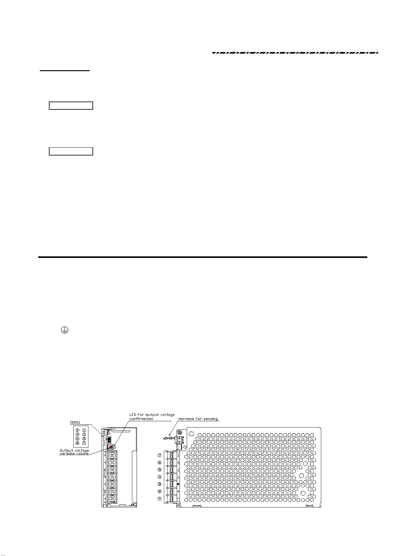
・You can adjust +Vout by using Output Voltage
Adjustment Potentiometer that is next to the
Over-current Protection(OCP)
connector (CN501).
・You can increase output voltage by turning clockwise.
If you need decrease, you can turn it the other way.
・The over-current protection works and the output is
・Please use it within the following range when you intercepted when becoming 110% or more of the
adjust the output voltage. output current ratings.
・Within +/- 10% rated output voltage. ・Remove the factor of the overload, and turn on the
・Do not use maximum output power. input again after a few minutes of cutting when
・Do not exceed rated output current. resetting it.
・Please avoid operation in the over-current state
for 10 seconds or more.
It will cause damage or isolation failure.
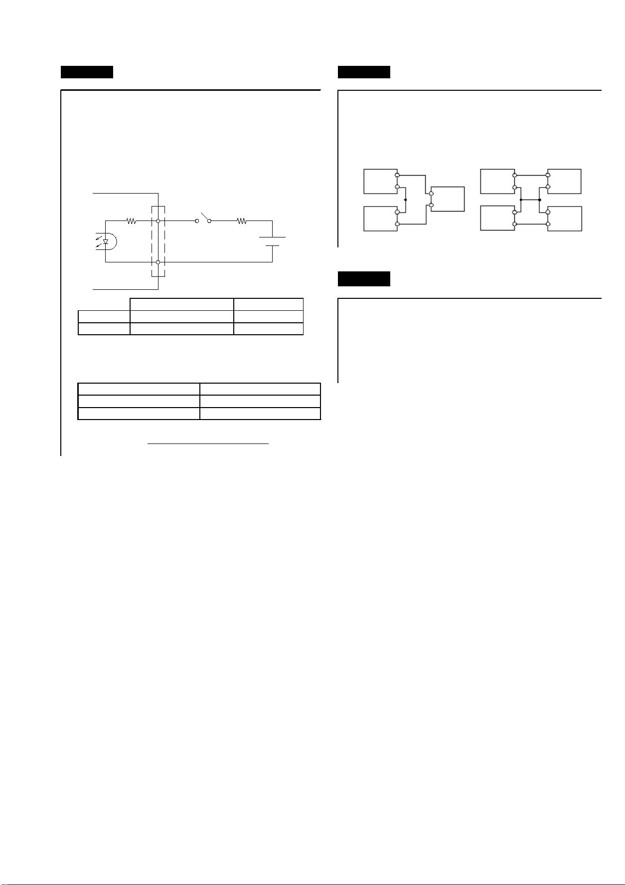
Over-Voltage Protection(OVP) Remote Sensing
・It detects when the output voltage exceeds by some ・
reasons, and the output is intercepted at once.
・
・When it works once, the over-voltage protection
continues the output interception while the input is
supplied.
・Turn it on again after a few minutes after intercepting ・
the input when resetting it.
・Note that the output voltage might be abnormal when
you turn it on again. (In this case, the over voltage
protection works again. )
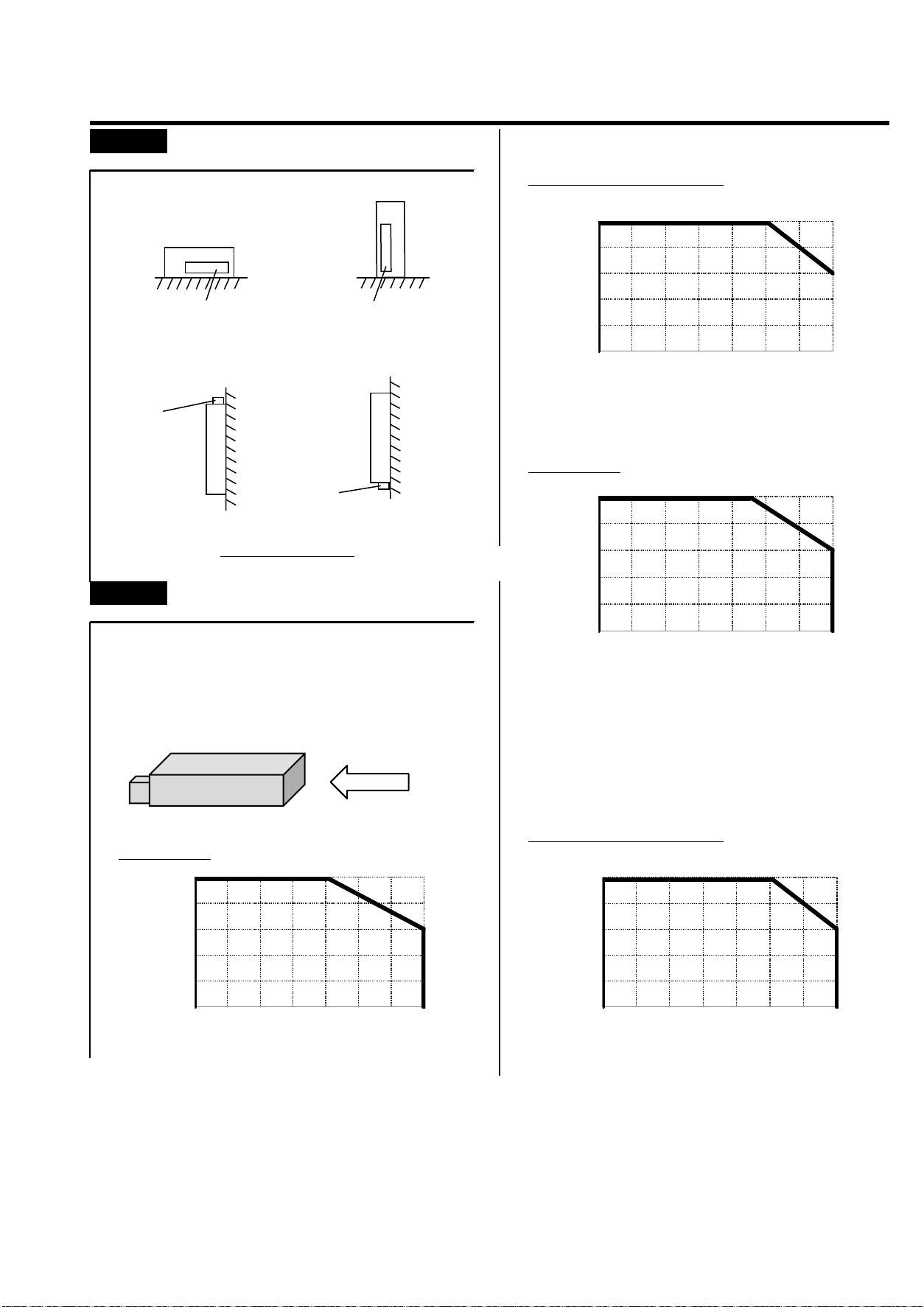
Over Temperature Protection (OTP)
・
・
・ ・
Note: We connected with wires between Pin#1 & Pin#2,
Also Pin #3 & Pin#4 as a default settings when we ship
from factory. This setting is for the customers who won't
use remote sensing feature. So, if you need to use this
feature, 1) Please remove the existing wires 2) Use
twisted cable for this feature to use shown as above.
In order to reset this, please disconnect AC input, then
confirm well cooling down the temperature inside the PSU
after several minutes. Then please apply AC input. Also
please confirm the forced air convection would well enough
to meet the air flow condition.
2-3
2-2
Please use within 0.3V voltage drop range to adjust.
2-1
2-7
It detects internal components temperature abnormally
getting higher, then turn off the output.
Once it detects and stops output, it stops supplying the
output even AC input supplies.
2-4
2-6
Then, please set up the output voltage range won't
exceed voltage range we specify.
Please twist the wires and install just besides in parallel
with wires for load as shown below.
2-5
Power Wire
Load
Connector
(CN501)

Remote On/Off circuit Series Operation
・The following (1) and (2) of Series operation can
・You can control turn On/Off of output by applying be used. However, Use the output current below
the voltage. the max output current in small one either of power
・
You can control it by applying the external voltage supplies with which the series is connected.
to the RC Connector, which is secondary circuit of
power supply. It can't be used in primary side circuit.
(1) (2)
Parallel Operation
・Parallel operation can not be used for the purpose
to increase output current.
Please connect external resistor R when using
6.5V or more in an impressed voltage.
2-9
SW ON
4.5V~12.5V
OFF
12.5V~24.5VDC
R
〔
Ω
〕
=
0.005
2-10
External Resistor:R
No Required
* Refer to the following
2-8
SW OFF
Less than 0.8V, or Open
ON
External Voltage level : E
4.5~12.5VDC
Voltage level -Pin #7 & #8.
Output
E-(1.1+1000×0.005)
+
-
電源
+
-
電源
電源
電源
+
- 負荷
負荷
負荷
+
-
+
-
+
-
+
-
ON
OFF
SW R
E
1kΩ
Power Supply
⑦+R
⑧-R
+
-
-
-
+
-
- -
-
+
+ +
+
+
Load
Load
Load
Power
Supply
Power
Supply
Power
Supply
Power
Supply

3
.
Mounting method / Direction
PFS300A-15、24、30、48
(a) (b)
(c) (d)
・For Medical 60601
PFS300A-12
Output derating
・
Please see the derating curve by output current
・( % of the load)
and can be used under several temperature conditions.
・
・To meet the requirement of 60950 PFS300A-15、24、30、48
PFS300A-12
15V,24V,30V,48V
■強制空冷:2m/s時(参考)
3-1
Mounting Method
Please refer to the derating curve under the condition when
you apply the 2.0m/s forced air flow as shown below.
3-2
PFS300A
2.0m/s
0
20
40
60
80
100
-10 0 10 20 30 40 50 60
L
o
a
d
(
%
)
Ambient Temperature (
℃
)
0
20
40
60
80
100
-10 0 10 20 30 40 50 60
L
o
a
d
(
%
)
Ambient Temperature(
℃
)
0
20
40
60
80
100
-10 0 10 20 30 40 50 60
L
o
a
d
(
%
)
Ambient Temperature (
℃
)
0
20
40
60
80
100
-10 0 10 20 30 40 50 60
L
o
a
d
(
%
)
Ambient Temperature (
℃
)_
Terminal Block Terminal Block
Terminal Block
Terminal Block
Mounting directions

Temperature limitation of each components surface
If you need to calculate more in detail to choose suitable fan in your application, please see the information below.
・Please use each temperature range of the surface of each component.
・Please test under your worst/most severe condition. We recommend you to use Type K thermocouple device.
* Please make sure to attach firmly with adhesive when you measure these temp.
・Please make sure 1) No air flow condition 2) Measure its highest heat spot
3) Operate PSU under all the temperature range and make sure it works stably.
Measured components
*Refer to the following drawing to specify each component location.
< Image from the top view >
MOS-FET
Diode
MOS-FET
Poly Switch
Thyristor
3-3
Max Temp (degree C)
100
110
115
P/N
Component name
C101
X Capacitor
Bridge Diode
Common mode choke
105
85
115
115
105
85
110
110
100
PC501
Photo Coupler
Poly Switch
D501
Secondary side Diode
115
T301
Transformer (Primary side coil)
T301
Transformer (Secondary side coil)
Q301
TH301
Q101
D102
SCR101
TH101
L101
D101
Q101 D102SCR101D101 PC501
D501 Q301
C101 L101
T301
(secondary coil )
TH101
T301
(primary coil) TH301
Table of contents
Other Daitron Power Supply manuals