2.Function explanation
Input voltage Remote On/Off circuit
・In
ut volta
e ran
e is sin
le
hase alternatin
・The remote control function is built-in.
current. 85~264Vac
47~63Hz
.・You can control the out
ut in On/Off b
a
l
in
・We recommend that you do not use this power the voltage.
su
l
unit outside of it's normal intended use in ・You can control it b
a
l
in
the external volta
e
order to avoid an
dama
e or malfunctions. to the RC Connector, which is secondar
circuit of
ower su
l
. It can't be used in
rimar
side circuit.
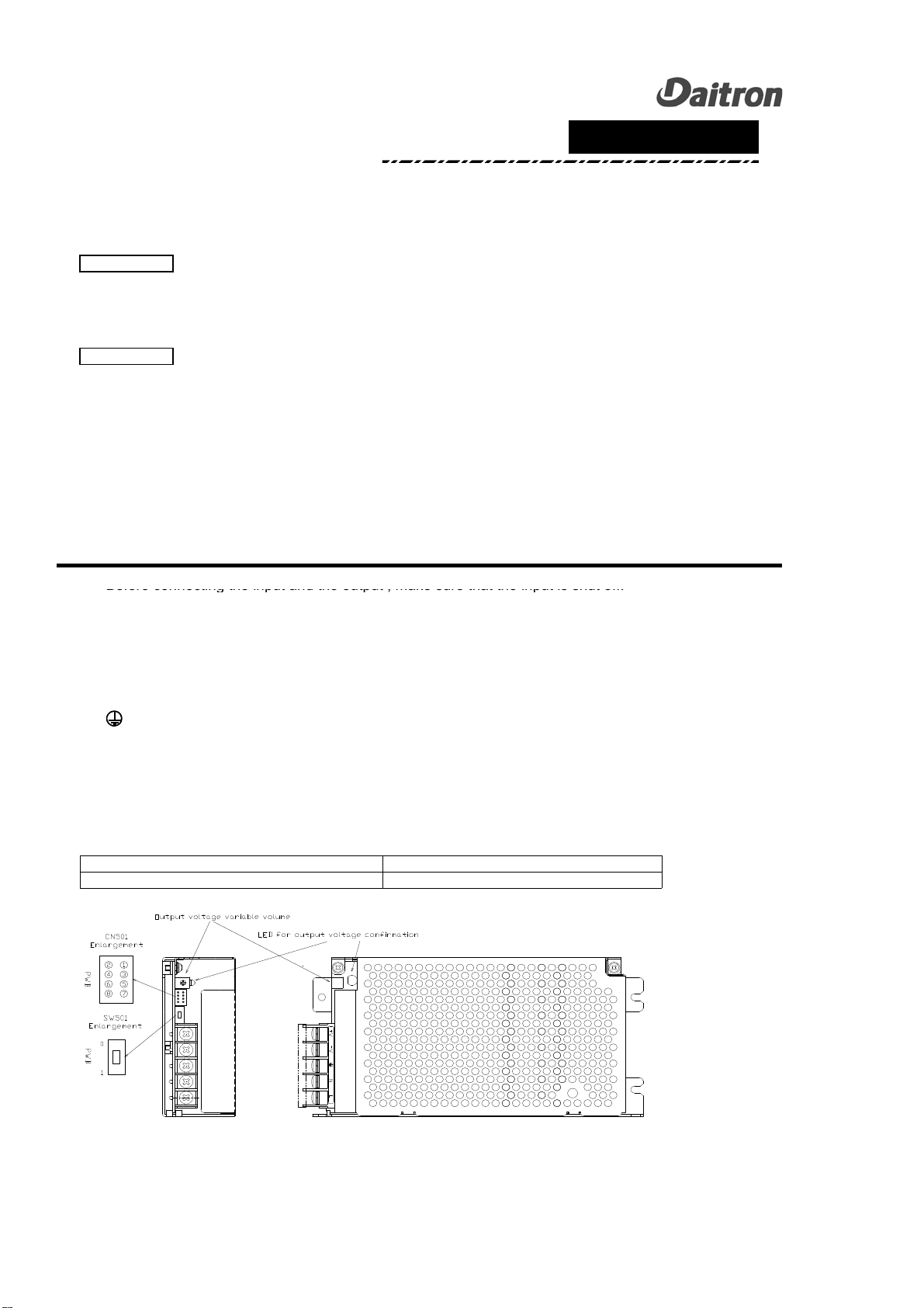
Output voltage setting
・You can ad
ust +Vout b
usin
Out
ut Volta
e
Ad
ustment Potentiometer that is next to the
connector
CN501
.
・You can increase out
ut volta
e b
turnin
clockwise.
If
ou need decrease,
ou can turn it the other wa
.
・Please use it within the followin
ran
e when
ou
ad
ust the out
ut volta
e.
・Within +/- 10% lated out
ut volta
e.
・Do not use maximum out
ut
ower.
・Do not exceed rated out
ut current.
Inrush Current Please connect external resistor R when using
6.5V or more in an im
ressed volta
e.
・
The inrush current limiting circuit is built-in
2-
SW OFF
2-
Voltage level -Pin #7 & #8.
4.5V~12.5V OFF
Less than 0.8V, or Open ON
2-1
2-3
Output
SW ON
ON
OFF
Connector(CN501)
SW R
E
1kΩ
Power Supply
⑦+R
⑧-R
-
.
・The inrush current limitin
circuit mi
ht released it
when the in
ut re-turnin
on time is short, because
SCR is used for the inrush current limitin
. So turn it
on a
ain enou
h after time.
・The first inrush current and the second inrush
current flow because it ado
ts SCR method for the
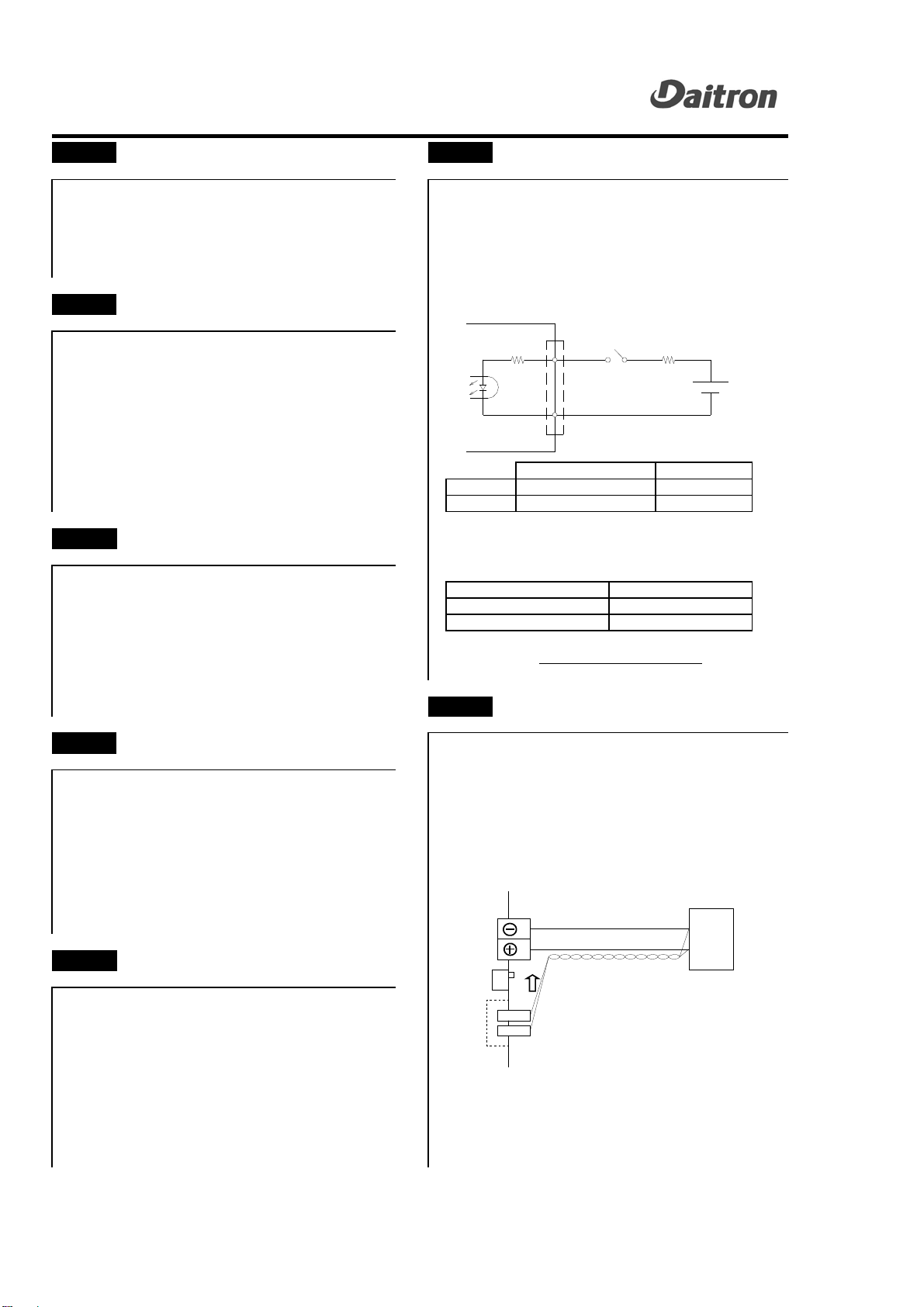
inrush current limiting circuit. Remote Sensing
Over-current Protection(OCP) ・The remote sensin
function is built-in.
・Line dro
between the to
the load device side
・The over-current
rotection works and the out
ut is and
ower su
l
terminal of the sensin
line use it
interce
ted when becomin
110% or more of the b
0.3V or less. Please note that
ower su
l
out
ut current ratin
s. terminal volta
e does not become out of a ratin
・Remove the factor of the overload, and turn on the range.
in
ut a
ain after a few minutes of cuttin
when ・The sensin
wire is done in the twist. And it uses it
resettin
it. alon
the load wire.
・Please avoid operation in the over-current state
for 10 seconds or more.
It will cause dama
e or isolation failure.
Over-Voltage Protection(OVP)
・It is detected when the out
ut volta
e rises b
some
causes
and the out
ut is interce
ted at once.
・When it works once
the over-volta
e
rotection
continues the out
ut interce
tion while the in
ut is
su
lied. ・Please confirm that the switch is "0", in the case
・Turn it on a
ain after a few minutes after interce
tin
that it does not use remote sensin
.
the in
ut when resettin
it. When the factor
is shi
ed, the switch is "0", and
・Note that the out
ut volta
e mi
ht be abnormal when the
ower su
l
can be used as it is when the
ou turn it on a
ain.
In this case
the over volta
eremote sensin
is not used.
rotection works a
ain.
2-5
4.5~12.5VDC
2-4
12.5V~24.5VDC
RᇖΩᇗ=E-(1.1+1000×0.005)
0.005
* Refer to the following
2-7
No Required
Load wire
Load
Switch
(SW501)
Connector
(CN501)
③-S
①+S
1
0
Power Supply