Daitsu CSAD UiAWP 100 User manual

SERIE
CSAD UiAWP 100/200/300 (PS)
EDITION
04/09
UMEn
USER MANUAL
MODULAR CHILLER INVERTER
CSAD UiAWP 100 (PS)
CSAD UiAWP 200 (PS)
CSAD UiAWP 300 (PS)

● This manual gives detailed description of the precautions
that should be brought to your attention during operation.
● In order to ensure correct service of the wire controller
please read this manual carefully before using the unit.
● For convenience of future reference, keep this manual after
reading it.
User Manual_________________________________________

● This manual gives detailed description of the
precautions that should be brought to your attention
during operation.
● In order to ensure correct service of the wire
controller please read this manual carefully before
using the unit.
● For convenience of future reference, keep this
manual after reading it.
User Manual_________________________________________

Contents
1 Safety Precautions ...........................................................................1
2 Overview of Wired Controller ...........................................................3
3 Menu Operations..............................................................................5
4 Installation Manual .........................................................................25
5 Failure Information and Code.........................................................37
6 Attached Table About Modbus .......................................................41
● This manual gives detailed description of the precautions
that should be brought to your attention during operation.
● In order to ensure correct service of the wire controller
please read this manual carefully before using the unit.
● For convenience of future reference, keep this manual after
reading it.
User Manual_________________________________________

1
The product and Operation and Installation Instructions record the following
content, including the operation method, how to prevent harms to others and
property losses, and how to use the product correctly and safely. Read the
text after understanding the content (identification and marker maps) below
carefully, and observe the precautions below.
[Note]: So-called "injuries" mean the harms not requiring hospitalization or
long-term treatment, generally referring to wounds, burns, or electric shocks.
Material damages refer to property and material losses.
!
Caution
!
Warning
!
1 Safety Precautions
Caution
Read the safety precautions carefully prior to installation.
The important safety precautions are provided below and must be observed.
Meanings of marks:
Means improper handling may lead to personal injuries or material damages.
Means improper handling may lead to death or serious injury.
After the installation work is completed, confirm that the trial operation is normal and hand
over the manual to the customer for keeping.
User Manual_________________________________________

2
It indicates "prohibited". The specific content of prohibition is provided using
graphics or text in the icon or nearby.
It indicates "mandatory". The specific mandatory content is provided using graphics
or text in the icon or nearby.
Icon
Name
Do not spray combustible spray to the wired controller directly; otherwise a fire may be
caused.
Do not perform operations with a wet hand or allow water to enter the wired controller;
otherwise the wired controller will be damaged.
Prohibited
Prohibited
Caution
in Use
Entrust your distributor or a professional to install the product. The installation operator
must have acquired the relevant professional knowledge.
In case of independent installation, wrong operations will lead to a fire, electric shock,
or injury.
Entrusted
installation
Warning
!
Do not install the product at a place where flammable gas
easily leaks. Once flammable gas leaks and stays around
the wired controller, a fire may be caused.
!
1 Safety Precautions
Caution
User Manual_________________________________________

3
2 Overview of Wired Controller
Turn on or off the
space operation
mode
Enter the menu
structure from
the home page
Navigate the
cursor on the
display/navigate
in the menu
structure/ adjust
the settings
Come back to
the up level Long press for
unlocking /locking
the controller
Go to the next step when
programming a schedule in the
menu structure / confirm a
selection/enter a submenu in
the menu structure
User Manual_________________________________________

4
2 Overview of Wired Controller
MON
20/11/2017
WEEKLY TIMER ON TIMER ON
ON
ONLINE
UNITES
16
10:35 A
COOL Tws
Tw
55
C
55
C
ERROR
E1
60%
45%
Heating mode
Cooling mode
Set temperature Tw
Current temperature Tw
Number of parallel units
Current ERROR
WEEKLY
TIME icon
Timer
icon
Water
pump on External electric
heater on
Compressor
operating
Fan on
Lock icon
Anti-freezing or
Silent
mode on
Centralized control
Alarm
icon
Units
operating
T5 55
C
Current temperature T5
manual defrost on
access of network
Fan operating
usage rate
60%
Compressor
operating usage rate
45%
User Manual_________________________________________

5
3 Menu Operations
3.1 Unlocking/Locking Operation
3.3 Setting Mode
When the wired controller is locked, press and
hold the "UNLOCK" button for 3s to unlock it,
when " " is not displayed; in the unlocked
status, press and hold the "UNLOCK" button
for 2s to lock it, when " " is displayed and the
wired controller cannot be operated; when
there is no operation for continuous 60s on
any page, the wired controller returns to the
home page and is locked automatically, and
the locking icon is displayed.
3.2 Power-on/off
b. Heating mode
a. Cooling mode
When the wired controller is unlocked and the
unit is on, "ON/OFF" can be pressed to power
off the unit under the home page only; when
the unit is off, press "ON/OFF" to power on the
unit. The mode can be switched under the
power-off mode only.
In Unlock mode, press the "MENU" button
to enter the menu setting interface, press
the "▼" and "▲" buttons to select "MODE"
and set a mode, and press the "OK" button
as shown in the above figure to access the
submenu (mode setting). As shown below:
two modes available.
MON
20/11/2017
ON
ONLINE
UNITES
16
10:35 A
COOL Tws
Tw
7
C
25
C
60%
45%
MON
20/11/2017
10:35 A
COOL Tws 7
C
Tw 25
C
MON
20/11/2017
10:35 A
Tws
Tw
55
C
25
C
HEAT
User Manual_________________________________________

3.4 User Menu
6
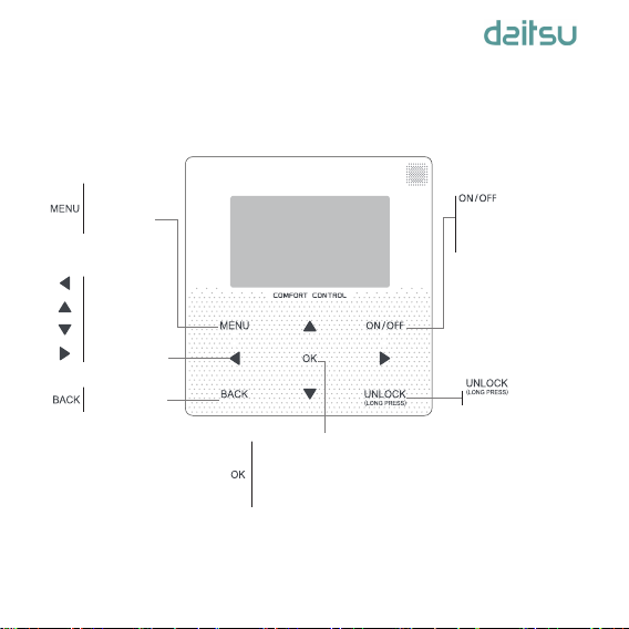
When the current mode button is selected
(blinking), press "◄" and "►" to set a
mode or temperature, and then press "▼"
and "▲" to adjust the mode and set
temperature value. After setting, press the
"OK" button to save the setting and go
back to the home page; or press the
"BACK" button to go back to the previous
interface; if there is no subsequent
operation in 60s, the setting is saved
automatically, and the system returns to
the home page.
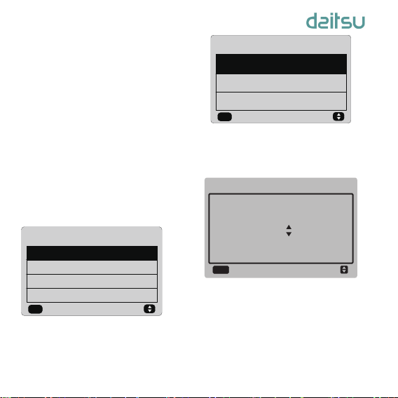
Select "USER MENU" to enter the user
menu. The interface display is as follows:
Select "QUERY" in the “USER MENU”
interface to access the query function. The
interface display and operation are as
follows:
The user first uses the "▼" and "▲"
buttons to select the address of module to
view (the offline address is skipped
automatically). Press the "OK" button to
access the next submenu or press "BACK"
to go back to the previous interface; during
operation on the menu page, press
"BACK" to go back to the previous
interface. After entry, the interface is
displayed as follows:
USER MENU
QUERY
TIMER
SILENT MODE
DOUBLE SETPOINT
1/2
ok
QUERY
USER MENU
TEMPERATURE COPENSATION
HEATER CONTROL(DISABLE)
HOT WATER SWITCH(DISABLE)
2/2
ok
TEMPERATURE COMPENSATION
USER MENU
SELECT THE QUERING ADDRESS
00
OK
QUERY
User Manual_________________________________________

7
RUNNING
MODE
CURRENT
SILENCE
MODE
ON COOL
NIGHT
SILENT
MODE1
BACK
STATE QUERY #00
OPERATION
STATE
◆
Temperature query:
Press "▼" and "▲" buttons to select
"TEMP QUERY" in the “QUERY” interface,
and press the "OK" button to enter the
interface. The interface display is as
follows:
◆
Setting the timer:
Press "▼" and "▲" buttons to select
"TIMER" in the “USER MENU” interface,
and press the "OK" button to enter the
interface. The interface display is as
follows:
◆
Setting the daily timer
Press "▼" and "▲" buttons to select
"DAILY TIMER" in the “TIMER” interface,
and press the "OK" button to enter the
interface. The interface display is as
follows:
QUERY #00
OK
SATAT QUERY
TMEP QUERY
TIMER
OK
DAILY TIMER
DATE AND TIME
WEEKLY SCHEDULE
◆
State query:
Press "▼" and "▲" buttons to select
"STATE QUERY" in the “QUERY”
interface, and press the "OK" button to
enter the interface. The interface display is
as follows:
TEMP QUERY
BACK
IN-LET
WATER
TEMP
#00
OUT-LET
WATER
TEMP
TOTAL
OUT-LET
WATER
TEMP
AMBLENT
TEMP
25℃25℃25℃25℃
User Manual_________________________________________

8
When the cursor stays at "ACT", press "▲"
and "▼" buttons to select the timer Timer1 or
Timer2 and press the”ON/OFF” button to
enable or disable daily timer function.
Press the "◄" and "►" buttons to select the
start time T.ON, end time T.OFF, mode and
temperature to be set, and then press the "▲"
and "▼" buttons to set the time, mode, and
temperature value. After setting, press "OK" to
confirm saving, or press "BACK" to cancel
setting and return to the previous interface.
If Time1 T.ON is set the same as Time1 T.OFF,
then the setting is invalid, the ACT option for
the timer of this segment jumps to "OFF", the
setting of Timer2 is the same as that of
Timer1, and the timing interval of Time2 can
cross with that of Time1.
For example, if Timer1 T.ON is set to 12:00
and Timer1 T.OFF is set to 15:00, then the
values of Timer2 T.ON and Time2 T.OFF can
be set in the range of 12:00-15:00. If the time
interval crosses, the machine will be powered
on at the time T.ON which is set in Timer1 or
Timer2,and will be powered off at the time
T.OFF which is set in Timer1 or Timer2.
After the daily timer function setting is
enabled, the icon “ TIMER ON” will be
displayed on the home page interface.
Only one setting is enabled between
“DAILY TIMER” and “WEEKLY
SCHEDULE”. If any of the pattern in
“WEEKLY SCHEDULE” is set to ON,
“DAILY TIMER” is disabled. “DAILY
TIMER” can be setted across days, but
“WEEKLY SCHEDULE” can’t be.
Users can set up to two timings, and set
the ON or OFF time (set the interval of time
to 10 minutes) 、operation mode(COOL
mode and HEAT mode at single water
pump control mode.) and temperature
setting for each segment of timing.
DAILY TIMER
OK
ACT
ON
ON
T.ON T.OFF MODE TEMP
10:00A 12:00A HEAT 40℃
01:00P 06:00P HEAT 40℃
User Manual_________________________________________

9
WEEKLY SCHEDULE
OK
ON
TIME
DATE AND TIME
DATE
OK
◆
Setting the weekly schedule:
Press the "▼" and "▲" buttons to select
"WEEKLY SCHEDULE" in the “TIMER”
interface, and press the "OK" button to
enter the interface. The interface display is
as follows:
Press "▲" and "▼" bottons to set the day the
user want from monday to sunday. and press
the “OK” button or press"◄" and "►" buttons
to choose “ON” then press “OK” button to
enter the time setting interface. The interface
is as follows:
◆
Setting date and time:
Press the "▼" and "▲" buttons to select
"DATE AND TIME" in the “TIMER”
interface, and press the "OK" button to
enter the interface. The interface display is
as follows:
OFF
Monday
OK
ACT
OFF
OFF
T.ON T.OFF MODE TEMP
10:00A 12:00A HEAT 40℃
01:00P 06:00P HEAT 40℃
The operation is the same as the operation of
daily timer.
When the setting of ACT is ON, then press the
“OK” button to enter the interface is as follwos:
WEEKLY SCHEDULE
OK
ON OFF
After the weekly schedule funtion setting is
enabled,the icon “ WEEKLY TIMER ON” will
be displayed on the home page interface.
User Manual_________________________________________

10
DAYMONTH
MAR. 1ST
2018
YEAR
DATE
OK
AM/PMMINUTE
00 PM
07
HOUR
TIME
OK
Press the "▲" and "▼" buttons to select the
date or time, and press the "OK" button to
access the lower-layer submenu:
Date setting operation instructions:
Press the "◄" and "►" buttons to select
“YEAT”, “MONTH” and “DAY”, press the "▲"
and "▼" buttons to set the parameter value,
and press the "OK" button to save the setting.
Time setting operation instructions:
Press the "◄" and "►" buttons to select
“HOUR” , “MINUTE” and “AM/PM”, press the
"▲" and "▼" buttons to adjust the parameter
value, and press the "OK" button to save the
setting.
◆
Silent mode :
Press the "▲" and "▼" buttons to select
"SILENT MODE" in the “USER MENU”
interface, and press the "OK" button to enter
the interface. The interface display is as
follows:
SILENT SODE
SELECT SILENCE MODE
STANDARD MODE
CURRENT MODE:
STANDARD MODE
12 3
ok
CURRENT MODE:
STANDARD MODE
User Manual_________________________________________

11
◆
Double Setpoint:
Press the "▲" and "▼" buttons to select
"DOUBLE SETPIONT" in the “USER MENU”
interface, and press the "OK" button to enter
the interface. The interface display is as
follows:
Press the "▲" and "▼" buttons to select the
ENABLE or DISABLE, and press the "OK"
button to save the setting.If setting the
DISABLE then return to the previous
interface.If setting the ENABLE then enter the
interface as follows:
Operation instructions:
Press the "◄" and "►" buttons to select
setpoint mode, press the "▲" and "▼" buttons
to set the parameter value,and press the "OK"
button to save the setting and return to the
previous interface,or press the "BACK" button
to cancel the setting and return to the previous
interface.
The main control board detects if the port
“TEMP-SW”is closed,and if the port is closed
the units will run according to the temperature
of “SET POINT COOL_2” or “SET POINT
HEAT_2”,other wise ,the units run according
to the temperature of “SET POINT COOL_1”
or “SET POINT HEAT_1”.
DOUBLE SETPOINT
OK
DOUBLE SETPIONT
DISABLE
Press the "◄" and "►" buttons to set the
parameter, and press the "OK" button to save
the setting and return to the previous
interface,or press the "BACK" button to cancel
the setting and return to the previous
interface.
After the silent mode function setting is
enabled,the icon " " will be displayed on the
home page interface.
DOUBLE SETPOINT
COOL_1
SET
POINT
HEAT_1
735730
SET
POINT
COOL_1
ok
SET
POINT
COOL_2
SET
POINT
HEAT_2
◆
Temperature compensation:
Press the "▲" and "▼" buttons to select
"TEMPERATURE COMPENSATION" in the
“USET MENU” interface, and press the "OK"
button to enter the interface. The interface
display is as follows:
User Manual_________________________________________

12
Press the "▲" and "▼" buttons to select the
COOL MODE and HEAT MODE, and press
the "OK" button to enter the interface. The
interface display is as follows:
Operation instructions:
Press the "◄" and "►" buttons to select the
cool mode or the heat mode, press the "▲"
and "▼" buttons to adjust the parameter
value.
press the "OK" button to save the setting and
return to the previous interface,or press the
"BACK" button to cancel the setting and return
to the previous interface.
The value of T4 COOL_1 and T4 COOL_2 of
temp compensation-cool mode need to satisfy
the condition of T4 COOL_2-T4 COOL_1 >=0.
TEMP COMPENSATION
OK
COOL MODE
HEAT MODE
TEMP COMPENSATION-HEAT MODE
SETPOINT T4 OFFSET
COOL_1 HEAT_2 _H
21510NO
T4
HEAT_1
ok
ENABLE
TEMP COMPENSATION-COOL MODE
SETPOINT T4 OFFSET
COOL_1 COOL_2 _C
253510NO
T4
COOL_1
ok
ENABLE
User Manual_________________________________________

13
3.5 Setting PROJECT MENU
◆
Entering the password:
Select "PROJECT MENU", and press the "OK"
button to enter the menu. The screen prompts
the user to enter the password, as shown
below:
The initial password is 6666 and cannot be
changed. Press the "▲" and "▼" buttons to
change the number to enter, and press the
"◄" and "►" buttons to change the bit code to
enter. After the number is entered, the display
is not changed. After entering the password,
press the "OK" button to enter the interface;
press the "BACK" button to go back to the
previous interface; the display is as follows if
the input is incorrect:
The query interface as follows is displayed if
the input is correct:
PROJECT MENU
PLEASE INPUT THE PASSWORD
0
OK
000
PROJECT MENU
SORRY,WRONG PASSWORD,
PLEASE INPUT AGAIN.
0
OK
000
OK
SET UNIT AIR-CONDITIONING
SET PARALLEL UNIT
PROJECT MENU
SET UNIT PROTECTION
SET DEFROSTING
SET HEATER
CHECK PARTS
1/2
OK
CONTROLLER SELECT
PUMP CONTROL (DISABLE)
PROJECT MENU
2/2
User Manual_________________________________________

14
◆
Set unit air-conditioning:
Press "▼" and "▲" buttons to select the
"SET UNIT AIR-CONDITIONING" in the
“PROJECT MENU” interface, and press
the "OK" button to enter the interface. The
interfaca display is as follows:
Presss the“◄” and “►” buttons to select the
desired option, and press “▲” and “▼”
buttons to set the temperature and press the
"OK" button to save the setting and return to
the previous interface,or press the "BACK"
button to cancel the setting and return to the
previous interface. If there is no operation in
60 seconds, the wired remote controller will
return to the home page.
◆
Set parallel unit:
Press "▼" and "▲" buttons to select the
"SET PARALLEL UNIT" in the “PROJECT
MENU” interface,and press the “OK” button
to enter the interface, The interface display is
as follows:
SET UNIT
Tw_heat
_Diff dT5_ON dT1S5
2℃2℃8℃10℃
Tw_cool
_Diff
OK
Presss the“◄” and “►” buttons to select the
desired option, and press “▲” and “▼” buttons
to set the temperature and press the "OK"
button to save the setting and return to the
previous interface,or press the "BACK" button
to cancel the setting and return to the previous
interface. If there is no operation in 60
seconds, the wired remote controller will return
to the home page.
◆
Set unit protection:
Press "▼" and "▲" buttons to select the "SET
UNIT PROTECTION" in the “PROJECT
MENU” interface,and press the “OK” button to
enter the interface, The interface display is as
follows:
SET PARALIET UNIT
Tw_diff
Ratio_
cool_
first
80s 2℃50% 50%
Tim_
Cap_Adj
OK
Ratio_
heat_
first
SET UNIT PROTECTION
T_Diff
_Pro
OK
12℃
User Manual_________________________________________

15
Press the “▲” and “▼” buttons to set the
values and press “OK” button to save the
setting and return to the previous interface,or
press the "BACK" button to cancel the setting
and return to the previous interface. If there is
no operation in 60 seconds, the wired remote
controller will return to the home page.
◆
Set defrosting:
Press "▼" and "▲" buttons to select the "SET
DEFROSTING" in the “PROJECT MENU”
interface,and press the “OK” button to enter the
interface, The interface display is as follows:
Presss the“◄” and “►” buttons to select the
desired option, and press “▲” and “▼” buttons
to set the temperature and press the "OK"
button to save the setting and return to the
previous interface,or press the "BACK" button
to cancel the setting and return to the previous
interface. If there is no operation in 60
seconds, the wired remote controller will return
to the home page.
SET DEFROSTING
T_
DEFROST_
IN
T_
FROST_
OUT
35min 0℃
T_FROST
OK
0℃
Select the“HEAT1”,and press the “OK” button
to access the interface, The interface display is
as follows:
◆
Set heater:
Press "▼" and "▲" buttons to select the
"SET HEATER" in the “PROJECT MENU”
interface,and press the “OK” button to
enter the interface, If it is controlled by
single water pump.The interface display is
as follows:
SET HEATER
OK
HEAT1
HEAT2(DISABLE)
SET HEAT1
Temp_
AuxHeat-
ON
Tw_
Heat1_
ON
DISABLE 5℃
ENABLE/
DISABLE
OK
25℃
Tw_
Heat1_
OFF
45℃
User Manual_________________________________________

16
3.6 Setting SERVICE MENU
◆
Entering the password:
Select "SERVICE MENU", and press the "OK"
button to enter the interface. The screen
prompts the user to enter the password, as
shown below:
Operation instructions:
When select modbus “YES”,and press “OK”
button to acess the function.User can use a
host computer to communicate with the wried
controller by modbus protocol,and these
operations on the wired controller as
“Power-ON/OFF”,“Setting Mode”,“Timer”and
“Setting temperature” are invalid.
Tips:The value of “Tw_Heat1_OFF” is bigger
than “Tw_Heat1_ON”.
HEAT2 function is disabled, so user can not
enter the HEAT2 interface.
◆
Check parts
Press "▼" and "▲" buttons to select the
"CHECK PARTS" in the “PROJECT
MENU” interface, and press the "OK"
button to enter the interface. The interfaca
display is as follows:
The screen displays conditions of all parts;
users can press “BACK” button to exit after
confirming.
◆
Controller select
Press "▼" and "▲" buttons to select the
"CONTROLLER SELECT" in the “PROJECT
MENU” interface, and press the "OK" button
to enter the interface. The interfaca display is
as follows:
BACK
SV1
CHECK PARTS
OFF
SV2
Pump
Heat1
Heat2
OFF
OFF
OFF
OFF
CONTROLLER SELECT
OK
MODBUS:
NO
User Manual_________________________________________
This manual suits for next models
3
Table of contents
Other Daitsu Inverter manuals
Popular Inverter manuals by other brands

Keysight Technologies
Keysight Technologies E8257D Configuration guide

Generac Power Systems
Generac Power Systems Air-cooled Generators Installation guidelines

GivEnergy
GivEnergy AC 3.0 installation manual

SolaX Power
SolaX Power X1-3.0-T-DL user manual

Fulling
Fulling DZB200M user manual

Harbor Breeze
Harbor Breeze LS001-W100E2-AA-M4PK1 quick start guide