Carmanah E Series User manual

E / F Series
TRAFFIC BEACON USER MANUAL
Carmanah Technologies Corp. | 250 Bay St, Victoria, BC V9A 3K5, Canada | 1.250.380.0052 | customerservice@carmanah.com | carmanahtraffic.com
For the R920-E/F, R820-E/F, R829-E/F, and R247-E/F flashing beacons
84323_MANUAL_TRA_E-F-Series_RevA

Carmanah Technologies Corp. | 250 Bay St, Victoria, BC V9A 3K5, Canada | 1.250.380.0052 | customerservi[email protected] | carmanahtraffic.com 2
E / F SERIES USER MANUAL
TABLE OF CONTENTS
Table of Contents
Table of Contents .....................................................................................................................................................2
1.0 Warnings and Precautions ................................................................................................................................4
1.1 Warranty Disclaimer ...................................................................................................................................4
1.2 Standards ...................................................................................................................................................4
1.3 Safety and Usage Precautions ...................................................................................................................4
1.4 System Components ..................................................................................................................................6
2.0 Introduction.........................................................................................................................................................7
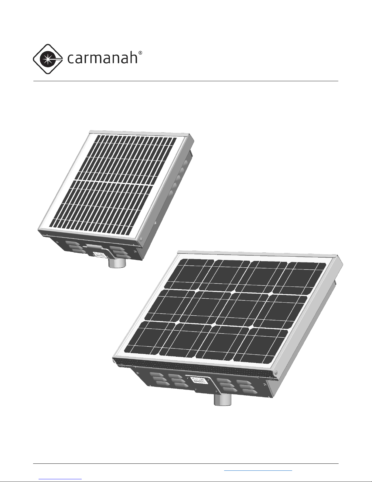
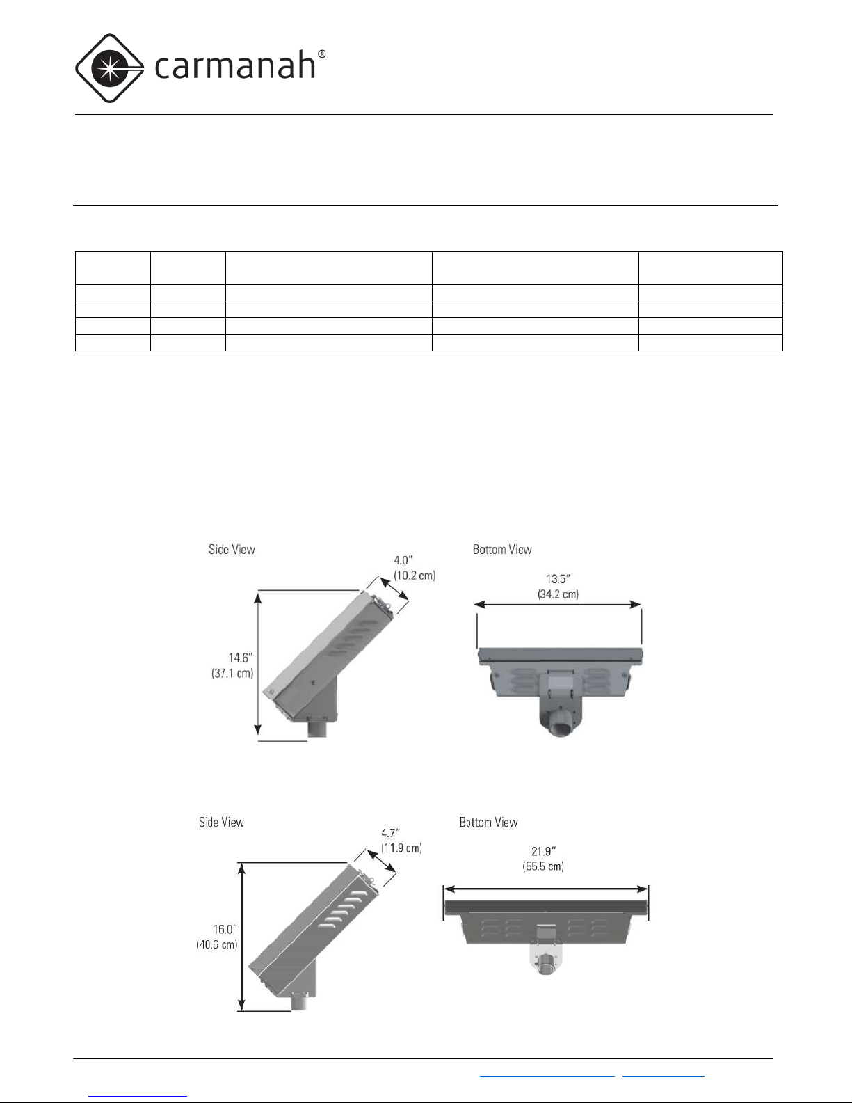
2.1 About the E and F Series............................................................................................................................7
2.2 Radio Communication ................................................................................................................................8
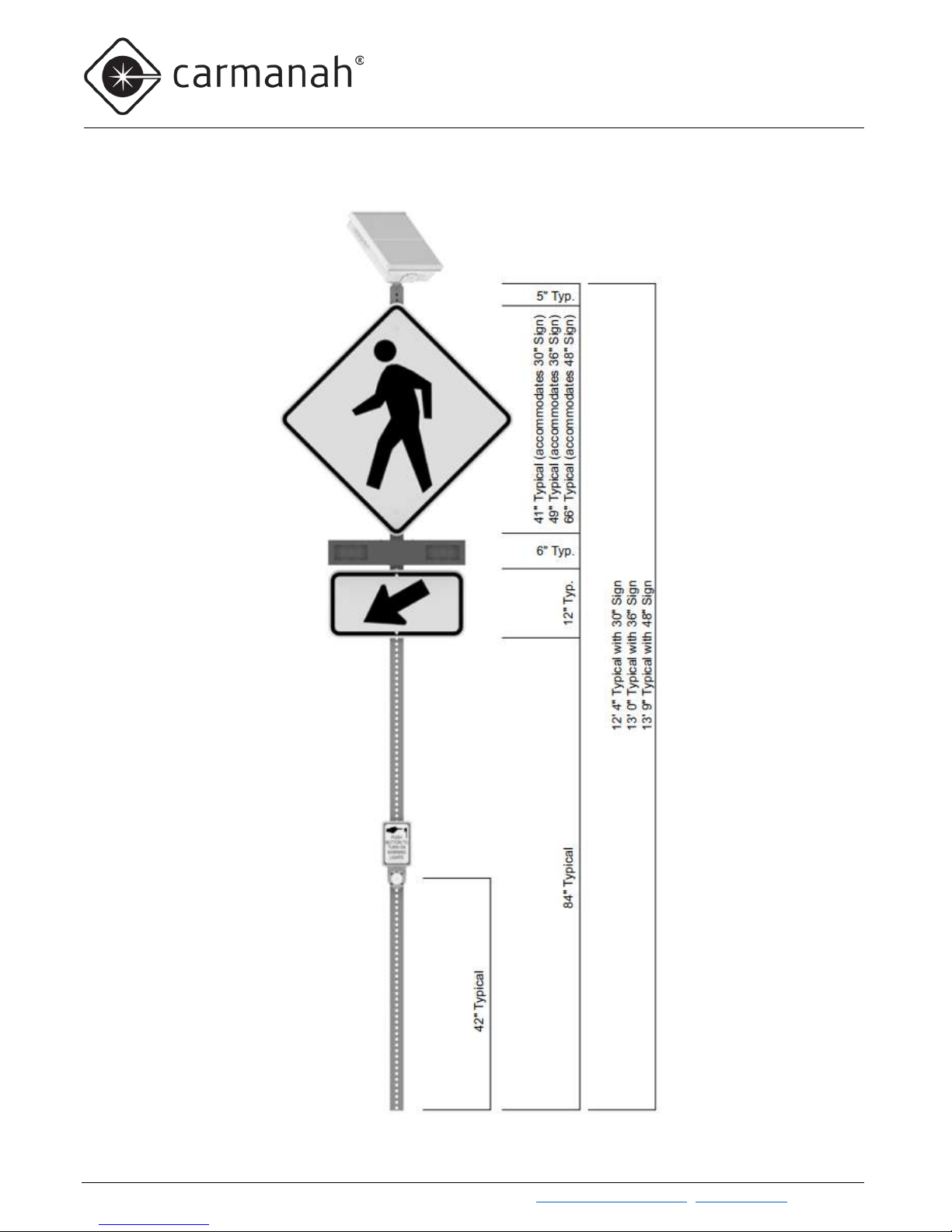
2.3 R920-E and R920-F: Pedestrian Crosswalk with RRFB Light Bars...........................................................8
2.4 R820-E and R820-F: Pedestrian Crosswalk with Circular Beacons ....................................................... 10
2.5 R829-E and R829-F: School Zone Flashing Beacon .............................................................................. 11
2.6 R247-E and R247-F: 24-Hour Flashing Beacon ..................................................................................... 12
2.7 RRFB Light Bars: Overview..................................................................................................................... 13
2.8 Circular Beacons: Overview .................................................................................................................... 13
2.9 LED Enhanced Signs: Overview ............................................................................................................. 14
2.10 Third-Party Devices: Overview ................................................................................................................ 14
3.0 Solar Engine Installation................................................................................................................................. 16
3.1 Tools and Materials Required.................................................................................................................. 16
3.2 Solar Engine Mounting to Round Post .................................................................................................... 17
3.3 Solar Engine Mounting to Square Post with Universal Cast Mount ........................................................ 18
3.4 Solar Engine Mounting to Square Post with Steel Mount........................................................................ 19
3.5 Solar Engine Mounting to Side of Post.................................................................................................... 20
3.6 Reinforced Signal Head for Integrated Solar Engine / Signal Head........................................................ 21
3.7 Integrated Solar Engine with Signal Head – Round Post........................................................................ 22
3.8 Integrated Solar Engine with Signal Head – Square Steel Post ............................................................. 24
3.9 Integrated Solar Engine with Signal Head – Square Wood Post ............................................................ 26
3.10 Integrated Solar Engine with Signal Head – Side of Post ....................................................................... 28
4.0 Fixture, Push Button, & Battery Installation ................................................................................................. 30
4.1 RRFB Light Bar Installation ..................................................................................................................... 30
4.2 Circular Beacon Installation ..................................................................................................................... 35
4.3 LED Enhanced Sign Installation .............................................................................................................. 36
4.4 Push Button Installation ........................................................................................................................... 37
4.5 Battery Installation ................................................................................................................................... 39
5.0 Installation of Optional Accessories ............................................................................................................. 43

Carmanah Technologies Corp. | 250 Bay St, Victoria, BC V9A 3K5, Canada | 1.250.380.0052 | customerservi[email protected] | carmanahtraffic.com 3
E / F SERIES USER MANUAL
TABLE OF CONTENTS
5.1 Calendar Upload / Override Switch Kit Installation.................................................................................. 43
5.2 RTC Time Switch Installation (F Series only) .......................................................................................... 44
5.3 Information Display Company Time Switch Installation (F Series only).................................................. 45
5.4 Applied Information or FCU Modem Kit Installation (F Series only)........................................................ 46
5.5 3PD Time Switch Supplementary Information......................................................................................... 48
5.6 DC Relay Kit Installation (F Series only) ................................................................................................. 50
5.7 Polara XAV Controller Kit Installation (F Series only) ............................................................................. 51
5.8 Campbell Guardian Audible Push Button Kit Installation (F Series only)................................................ 52
6.0 Energy Management System Programming and Testing............................................................................ 52
6.1 EMS On-Board User Interface Operation................................................................................................ 52
6.2 R920-E/F Programming........................................................................................................................... 65
6.3 R820-E/F Programming........................................................................................................................... 65
6.4 R829-E/F Programming........................................................................................................................... 65
6.5 R247-E/F Programming........................................................................................................................... 65
7.0 Commissioning Checklist............................................................................................................................... 66
8.0 Maintenance and Product Care...................................................................................................................... 67
8.1 Fuse Replacement................................................................................................................................... 67
8.2 Battery Replacement ............................................................................................................................... 68
8.3 EMS Replacement................................................................................................................................... 68
8.4 EMS Recycling ........................................................................................................................................ 70
9.0 Troubleshooting .............................................................................................................................................. 71
9.1 BIST Error Codes .................................................................................................................................... 72
10.0 Customer Service and Warranty .................................................................................................................. 74
10.1 Additional Products.................................................................................................................................. 74
10.2 Glossary................................................................................................................................................... 75

Carmanah Technologies Corp. | 250 Bay St, Victoria, BC V9A 3K5, Canada | 1.250.380.0052 | customerservi[email protected] | carmanahtraffic.com 4
E / F SERIES USER MANUAL
1.0 WARNINGS AND PRECAUTIONS
1.0 Warnings and Precautions
The following symbols indicate important safety warnings and precautions throughout this manual:
WARNING indicates that serious bodily harm or death may result from failure to adhere to the
precautions.
CAUTION indicates that damage to equipment may result if the instructions are not followed.
NOTE suggests optimal conditions and provides additional information.
1.1 Warranty Disclaimer
This manual will familiarize you with the features, operation standards, and installation of Carmanah's E and F
Series flashing beacons. Failure to comply with the use, storage, maintenance, installation or placement
instructions detailed in this manual could void the warranty.
1.2 Standards
Perform all installation, wiring, grounding and maintenance in conformance with local building and electrical
codes. Adherence to the National Electrical Code (NEC) is mandatory to comply with any certification markings.
Non-adherence to code may void the warranty.
1.3 Safety and Usage Precautions
Batteries are shipped fully charged. Use extreme caution when handling the batteries as they can
generate hazardous short-circuit currents. Remove all jewelry (bracelets, metal-strap watches,
etc.) before handling the batteries.
Solar panels produce DC electricity when exposed to light and can therefore produce an
electrical shock or burn. To render solar panels inoperative, remove them from sunlight or fully
cover their front surface with an opaque material.
Before lifting any heavy or bulky equipment, ensure the load is secured so moving parts do not
shift, and that it can be lifted as far as needed without back strain or loss of grip. Installation may
require more than one person.

Carmanah Technologies Corp. | 250 Bay St, Victoria, BC V9A 3K5, Canada | 1.250.380.0052 | customerservi[email protected] | carmanahtraffic.com 5
E / F SERIES USER MANUAL
1.0 WARNINGS AND PRECAUTIONS
Ensure the equipment is not powered during installation and wiring of the system.
Recheck all completed wiring for proper polarity prior to energizing the system.
Changes or modifications to Carmanah equipment not expressly approved by Carmanah could
void both the user's authority to operate the equipment and the warranty.
All Carmanah traffic products use a constant-current LED output circuit. Not all traffic beacons
are compatible with this output. Please contact Carmanah for additional information and
guidance when adding or replacing beacons or other hardware.

Carmanah Technologies Corp. | 250 Bay St, Victoria, BC V9A 3K5, Canada | 1.250.380.0052 | customerservi[email protected] | carmanahtraffic.com 6
E / F SERIES USER MANUAL
1.0 WARNINGS AND PRECAUTIONS
1.4 System Components
Solar Engine
(E Series shown)
Mounting Adapters
RRFB Light Bars, Circular
Beacons, LED Enhanced
Signs
Pedestrian
Push Button
EMS
Batteries
Solar
Panels
Onboard
User
Interface
(OBUI)
Antenna
Ambient Light
Sensor (not
visible)

Carmanah Technologies Corp. | 250 Bay St, Victoria, BC V9A 3K5, Canada | 1.250.380.0052 | customerservi[email protected] | carmanahtraffic.com 7
E / F SERIES USER MANUAL
2.0 INTRODUCTION
2.0 Introduction
2.1 About the E and F Series
The Carmanah E and F Series products consist of the following models:
E-Series
Models
F-Series
Models
Applications
LED type(s)
Radio
Communication
R920-E
R920-F
Pedestrian crosswalks
RRFB or LED Enhanced Signs
Standard
R820-E
R820-F
Pedestrian crosswalks
Circular beacons or LED signs
Standard
R829-E
R829-F
School zones, calendar-based
Circular beacons or LED signs
Optional
R247-E
R247-F
Continuous 24-7 operation
Circular beacons or LED signs
N/A
The E Series models all share a common compact solar engine, while the F Series models share a common,
larger solar engine with a more powerful solar panel and higher-capacity batteries. The F Series can also
accommodate third-party devices within its larger solar engine. While all E and F Series products share the same
user interface on the Energy Management System (EMS) controller, different models and configurations may
differ in behavior, types of fixture, fixture harnesses, wireless operation, and other aspects. Contact Carmanah if
you would like to repurpose a system from its original model and configuration. Each system will be described in
full later in this user manual.
E-Series Solar Engine Dimensions
F-Series Solar Engine Dimensions

Carmanah Technologies Corp. | 250 Bay St, Victoria, BC V9A 3K5, Canada | 1.250.380.0052 | customerservi[email protected] | carmanahtraffic.com 8
E / F SERIES USER MANUAL
2.0 INTRODUCTION
2.2 Radio Communication
Radio communication between products is standard in R820-E/F and R920-E/F systems and is an option in
R829-E/F systems. In addition to the E and F Series, Carmanah also manufactures larger, cabinet-based G
Series versions of the R920, R820, R829, and R247 products. Wireless communication works seamlessly
between products regardless of whether they are E, F, or G Series. R820 and R920 systems will also activate
each other when a pedestrian pushes the push button.
The radio modules use 2.4GHz DSSS (Direct Sequence Spread Spectrum) with an AES128 encrypted signal and
have been tested with clear line of sight (with no nearby interference or reflected signals) to 1,000 feet (305
meters). Performance is reduced if clean line of sight is not possible.
The E and F Series products use a low-profile antenna that does not require any special orientation or adjustment
and is immune to vandalism.
2.3 R920-E and R920-F: Pedestrian Crosswalk with RRFB Light Bars
Overview
The R920-E/F solar LED Rectangular Rapid Flashing Beacon (RRFB) products are ideal for uncontrolled
pedestrian-activated crosswalk applications. Multiple R920 units can be combined to create a complete crosswalk
set. Each R920 is radio-controlled, and each synchronizes flashing with the other R820s and R920s in the group.
The system will flash for a pre-set duration (field adjustable) upon activation of the push button. Spread-spectrum
wireless communications activates the light bars across the street or in advance of the crossing. A typical
installation consists of two pairs of light bars, with each pair mounted on poles at opposite ends of the crosswalk.
Wireless communication between units means that R920s require no trenching of cables across the roadway.
Details on RRFB light bars can be found in Section 2.7 and Section 4.1.
As an alternative to light bars, R920 systems can be configured with LED Enhanced Signs. Details on LED
Enhanced Signs can be found in Section 2.9 and Section 4.3.
Typical R920 Configurations
R920-E with Single Light Bar and
Push Button (uni-directional)
R920-E with Dual Light Bar and
Push Button (bi-directional)
R920-E Advance Warning with
single Light Bar and No Push
Button (uni-directional)

Carmanah Technologies Corp. | 250 Bay St, Victoria, BC V9A 3K5, Canada | 1.250.380.0052 | customerservi[email protected] | carmanahtraffic.com 9
E / F SERIES USER MANUAL
2.0 INTRODUCTION
Typical R920 Configurations, cont’d

Carmanah Technologies Corp. | 250 Bay St, Victoria, BC V9A 3K5, Canada | 1.250.380.0052 | customerservi[email protected] | carmanahtraffic.com 10
E / F SERIES USER MANUAL
2.0 INTRODUCTION
2.4 R820-E and R820-F: Pedestrian Crosswalk with Circular Beacons
Overview
Multiple R820-E/F units can be combined to create a complete crosswalk set. Each R820 is radio-controlled, and
each synchronizes flashing with the other R820s and R920s in the group. The system will flash for a pre-set
duration (field adjustable) upon activation of the push button. Wireless communication activates the beacons
across the street or in advance of the crossing. A typical installation consists of two pairs of flashing circular
beacons, with each pair mounted on poles at opposite ends of the crosswalk. Wireless communication between
units means that R820s require no trenching of cables across the roadway.
R820s can also be wirelessly controlled by an R829 master controller. The R820s and R829 operate together
based on the schedule programmed into the R829’s internal calendar.
Details on circular beacons can be found in Section 2.8 and Section 4.2.
As an alternative to circular beacons, R820 systems can be configured with LED Enhanced Signs.Details on
LED Enhanced Signs can be found in Section 2.9 and Section 4.3.
Typical R820 Configuration

Carmanah Technologies Corp. | 250 Bay St, Victoria, BC V9A 3K5, Canada | 1.250.380.0052 | customerservi[email protected] | carmanahtraffic.com 11
E / F SERIES USER MANUAL
2.0 INTRODUCTION
2.5 R829-E and R829-F: School Zone Flashing Beacon
Overview
The R829-E/F School Zone Flashing Beacon systems operate on a programmable calendar used to set the days
and times when the beacon(s) will flash. There are four ways that an R829 system can follow a calendar
schedule:
1) A non-wireless R829 can operate on its own, automatically flashing based on the schedule programmed
into its internal calendar.
2) A non-wireless R829 can also be turned on and off through a hard-wired switch. This switching function
can be provided by an override box, a third-part time switch, or both.
3) A wireless R829 can operate as the master controller in a group of wireless Carmanah E, F, or G Series
traffic products
4) Other Carmanah E, F, or G Series products respond to commands from a wireless R829 master
controller system and operate according to the master’s calendar schedule.
Details on circular beacons can be found in Section 2.8 and Section 4.2.
As an alternative to circular beacons, R829 systems can be configured with LED Enhanced Signs.Details on
LED Enhanced Signs can be found in Section 2.9 and Section 4.3.
E Series products can also operate with an externally mounted time switch, while F Series
products feature optional time switch kits that allow various third-party products to be mounted
within the solar engine. See Section 2.10 and Section 5.0 for details.
Typical R829 Configuration

Carmanah Technologies Corp. | 250 Bay St, Victoria, BC V9A 3K5, Canada | 1.250.380.0052 | customerservi[email protected] | carmanahtraffic.com 12
E / F SERIES USER MANUAL
2.0 INTRODUCTION
Internal Calendar (Standard on R829, optional on other systems)
The R829 is equipped with an internal calendar that is programmed via USB to automatically activate and
deactivate school zone flashers on a user-defined schedule of up to 512 days.The calendar is programmed
using an intuitive Microsoft Windows-based graphical user interface. Once the program is established for one
system, the settings can be uploaded to other R829 units onsite with a laptop PC. A USB cable is part of the
calendar programming kit and is provided coiled up inside the R829 solar engine.
Eight different day schedule types can be defined (including OFF all day). Each day type can be configured for
up to eight ON periods of adjustable duration.Refer to the support document “R829 School Zone Calendar
Configuration Instructions” for additional information and complete programming instructions.
Ensure you obtain the latest copy of the calendar software (Version 1.2.0 as of November 2018).
Older versions of the calendar software will not operate correctly with the newest version of traffic
firmware. Minimum Windows 7 operating system is required (32-bit or 64-bit). The software can
be obtained by contacting Carmanah Traffic Sales. The software is also included on a USB
memory stick in the calendar software programming kit, which also includes a 32-foot active
USB extension harness which can be used to program a system’s calendar from a vehicle.
See Section 5.1 for more information about related accessory calendar upload / override
switch kit.
2.6 R247-E and R247-F: 24-Hour Flashing Beacon
Overview
The R247-E/F Flashing Beacon flashes continuously 24 hours per day 7 days per week and is used for a wide
range of warning applications such as stop lights and low bridges.
The R247-E can be turned off when required using the optional Override Box kit, see Section 5.1.
Details on circular beacons can be found in Section 2.8 and Section 4.2.
As an alternative to circular beacons, R247 systems can be configured with LED Enhanced Signs. Details on
LED Enhanced Signs can be found in Section 2.9 and Section 4.3.
Typical R247 Configuration
R247-E with Integrated Signal Head

Carmanah Technologies Corp. | 250 Bay St, Victoria, BC V9A 3K5, Canada | 1.250.380.0052 | customerservi[email protected] | carmanahtraffic.com 13
E / F SERIES USER MANUAL
2.0 INTRODUCTION
2.7 RRFB Light Bars: Overview
E Series and F Series products support up to four (4) RRFB light bar fixtures. The FHWA Interim Approval 21
March 20th, 2018 defines the flash pattern of the RRFB and specifies the J595 standard for photometrics. Each
light bar consists of a left and right module, with each module having eight (8) LEDs connected in series. In
addition, each end of a light bar has a single “confirmation” LED that pedestrians can see from across the street
and know with confidence that the light bars are flashing in response to their pressing of the pedestrian push
button. Opaque adhesive covers are included to optionally cover the confirmation LED if desired.
See Section 4.1 for information on installing and aiming light bars.
2.8 Circular Beacons: Overview
E Series and F Series products support up to four (4) circular beacons.The beacons are industry-standard
equipment and comply with MUTCD and ITE flash patterns, color, beam shape, and intensity. Signal heads for
integrated mounting of the solar engine are specially reinforced for strength. Beacon wiring is provided with a
convenient terminal strip inside the signal head for easy wire connection.
Do not mix different sizes or colors of LED circular beacons on the same EMS.
Three (3) circular beacons in a system must be either wired in parallel or use a “Unison” flash
pattern to avoid current imbalance and ensure all fixtures receive the same amount of current
while flashing and therefore produce the same brightness.
All Carmanah traffic products use a constant-current LED output circuit. Not all traffic beacons
are compatible with this output. Please contact Carmanah for additional information and
guidance when adding or replacing beacons or other hardware.
See Section 4.2 for information on installing circular beacons.
Dual Confirmation Light
– No Opaque Cover
Single Confirmation Light
– Using Opaque Cover

Carmanah Technologies Corp. | 250 Bay St, Victoria, BC V9A 3K5, Canada | 1.250.380.0052 | customerservi[email protected] | carmanahtraffic.com 14
E / F SERIES USER MANUAL
2.0 INTRODUCTION
2.9 LED Enhanced Signs: Overview
In addition to RRFB light bars and circular beacons, E Series and F Series products can power LED Enhanced
Signs.LED Enhanced Signs are available in a variety of formats including stop and pedestrian crosswalk
signage. LED Enhanced Signs are electrically connected and driven directly by the EMS like other traffic fixtures.
LED Enhanced Signs have the same degree of intensity and flash pattern control as other fixtures.
Do not mix different sizes or LED counts of LED Enhanced Signs or mix LED Enhanced Signs
with other types of fixtures. Mixing fixture types is possible with Carmanah’s dual-EMS cabinet-
based G Series.
If powering three (3) LED Enhanced Signs in a system, they must be either wired in parallel or
use a “Unison” flash pattern to avoid current imbalance and ensure all signs receive the same
amount of current while flashing and therefore produce the same brightness.
See Section 4.3 for information on installing LED Enhanced Signs.
2.10 Third-Party Devices: Overview
A third-party device (3PD) is non-Carmanah equipment that interacts with the system in one or more ways:
•The E/F Series provide a status signal to 3PD (e.g. Digital Output signals when E Series fixtures are flashing,
allowing 3PD equipment such as overhead lighting to activate)
•The 3PD provides control signal to E/F Series (e.g. time switch, passive pedestrian detection, water level
detectors)
•The E/F Series only provides power to 3PD (e.g. radio/communications)
The F Series is available with several optional 3PD kits which allow the installation of the 3PD within the F Series
solar engine:
•The F Series RTC/IDC time switch kit option allows the installation of an RTC or IDC time switch and
includes a mounting plate, switch mounting hardware, and a pre-wired harness with a connector that plugs
into the time switch. (Time switch not included.) For installation information see Section 5.2, Section 5.3 and
Section 5.5.
•The F Series Applied Information modem kit option allows the installation of an AI time switch and cellular
modem. It includes mounting hardware, an antenna, and a prewired, connectorized harness to interface

Carmanah Technologies Corp. | 250 Bay St, Victoria, BC V9A 3K5, Canada | 1.250.380.0052 | customerservi[email protected] | carmanahtraffic.com 15
E / F SERIES USER MANUAL
2.0 INTRODUCTION
between the F Series and the AI time switch and modem. (AI time switch/modem not included). For
installation information see Section 5.4 and Section 5.5.
•The F Series Relay kit option comes with a 10A DC relay prewired to the F Series EMS. For installation
information see Section 5.6.
•The F Series Polara XAV controller kit option includes the Polara XAV controller prewired for the Polara
XAV2E audible push button. Push button station harness length options are 16ft, 36ft, or 75ft. For installation
information see Section 5.7.
•The F Series Campbell Guardian audible push button kit includes a prewired harness for a Campbell
Guardian audible push button. For installation and more information see Section 5.8.
Contact Carmanah for additional support in connecting and configuring the above the devices or
other third-party devices.

Carmanah Technologies Corp. | 250 Bay St, Victoria, BC V9A 3K5, Canada | 1.250.380.0052 | customerservi[email protected] | carmanahtraffic.com 16
E / F SERIES USER MANUAL
3.0 SOLAR ENGINE INSTALLATION
3.0 Solar Engine Installation
Ensure the installation location has an unobstructed view of the sun’s path.
Obstructions such as trees or buildings could significantly reduce the amount of
sunlight on the solar panel. Shade analysis is highly recommended to understand how
shadows will change according to the time of year. Contact Carmanah for a detailed
examination and solar simulations for your site.
3.1 Tools and Materials Required
The following tools and materials may be required to mount your Carmanah flashing beacon depending on the
model and configuration:
a. Imperial socket set
b. Crescent wrench
c. Tap set
d. Imperial Allen-Wrench set
e. Fish tape
f. Level
g. Compass or pre-determined equatorial
direction
h. Drill and drill bits
i. Fine-tip felt marker
j. Multi-bit screwdriver
k. Pelco Roger-Wrench (some configurations)
l. Hook spanner wrench, 1-1/2” trade size
(some configurations)
m. Ladder or lift device
n. Lithium grease

Carmanah Technologies Corp. | 250 Bay St, Victoria, BC V9A 3K5, Canada | 1.250.380.0052 | customerservi[email protected] | carmanahtraffic.com 17
E / F SERIES USER MANUAL
3.0 SOLAR ENGINE INSTALLATION
3.2 Solar Engine Mounting to Round Post
1. Install supplied longer set screws into mount, if required.
2. Thread mount onto solar engine and tighten.
3. Tighten set screw or clamp bolt at top of mount, if present.
4. Install on post and orient solar engine to face south (for Northern Hemisphere locations).
5. Tighten set screws onto post.

Carmanah Technologies Corp. | 250 Bay St, Victoria, BC V9A 3K5, Canada | 1.250.380.0052 | customerservi[email protected] | carmanahtraffic.com 18
E / F SERIES USER MANUAL
3.0 SOLAR ENGINE INSTALLATION
3.3 Solar Engine Mounting to Square Post with Universal Cast Mount
1. Obtain lock nut included with solar engine. Fully tighten against bottom of solar engine.
2. Thread solar engine fully onto mount.
3. Install mount onto square post and tighten bolts onto post.
4. Loosen less than one turn until solar engine faces south (for Northern Hemisphere locations).
5. Tighten top bolt on mount.

Carmanah Technologies Corp. | 250 Bay St, Victoria, BC V9A 3K5, Canada | 1.250.380.0052 | customerservi[email protected] | carmanahtraffic.com 19
E / F SERIES USER MANUAL
3.0 SOLAR ENGINE INSTALLATION
3.4 Solar Engine Mounting to Square Post with Steel Mount
1. Install mount onto square post using suitable fasteners (not supplied). On 2" square posts, mount goes
over post. On 2.5" square posts, mount goes inside post. Leave enough room between top of post
and bottom of mount for solar engine nipple and octagonal nut.
2. Orient two serrated lock rings so the teeth mesh and place onto mount. Align tabs on bottom lock ring
with slots in mount.
3. Install solar engine through lock rings and onto mount. Align tabs on top lock ring with slots in solar
engine.
4. Thread octagonal nut onto solar engine nipple.
5. Orient solar engine to face south (for locations in Northern Hemisphere).
6. Tighten octagonal nut and set screw.

Carmanah Technologies Corp. | 250 Bay St, Victoria, BC V9A 3K5, Canada | 1.250.380.0052 | customerservi[email protected] | carmanahtraffic.com 20
E / F SERIES USER MANUAL
3.0 SOLAR ENGINE INSTALLATION
3.5 Solar Engine Mounting to Side of Post
\
1. Obtain lock nut included with solar engine. Fully tighten against bottom of solar engine.
2. Thread octagonal nut with set screw onto bottom of solar engine.
3. Insert other octagonal nut into channel in side of post mount so it lines up with hole in top of mount.
4. Thread solar engine all the way onto nut in channel. Loosen less than one turn until solar engine faces
south (for Northern Hemisphere locations).
5. Tighten top octagonal nut down against mount, then tighten two set screws within octagonal nuts.
Other manuals for E Series
9
This manual suits for next models
9
Table of contents
Other Carmanah Inverter manuals
Popular Inverter manuals by other brands

Hoymiles
Hoymiles HM-2000T-S Series Quick installation guide

Kuhne electronic
Kuhne electronic MKU 57 G4 manual

Power Electronics
Power Electronics SD 500 Series Getting started manual

Afore
Afore HNS1509TL installation manual

Helvi
Helvi COMPACT 306HF instruction manual

SMA
SMA SUNNY BOY 2500 Quick installation guide